LG-Nortel ARIA SOHO User manual

I
ARIA SOHO
Quick Start Guide

ARIA SOHO Quick Start Guide
I
Table of Contents
1 SYSTEM OVERVIEW ...........................................................................................1
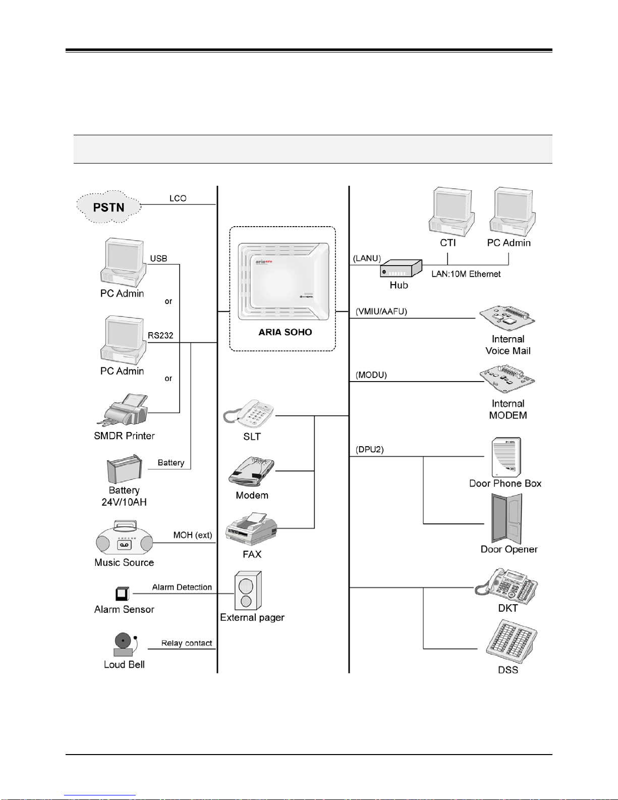
1.1 System Connection Diagram ...........................................................................................1
1.2 System Components.........................................................................................................2
2 INSTALLATION ....................................................................................................3
2.1 KSU Installation.................................................................................................................3
2.1.1 Unpacking ................................................................................................................................. 3
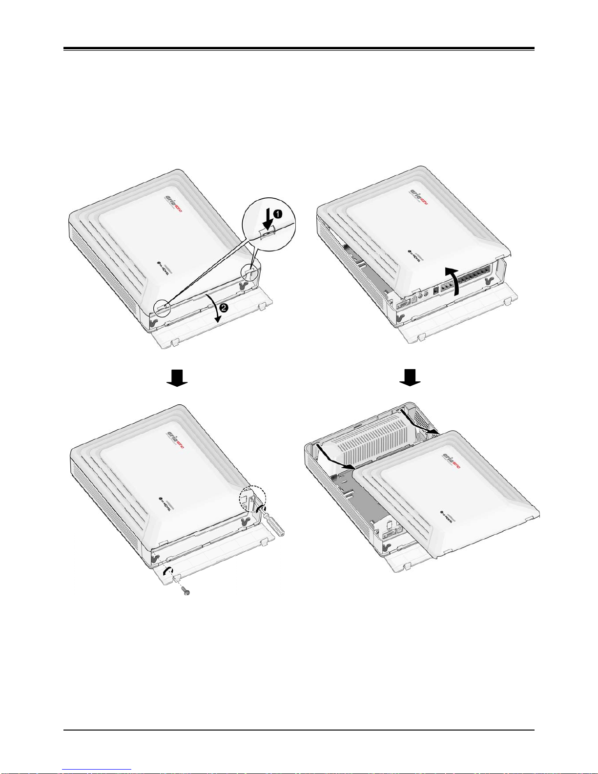
2.1.2 Opening and Closing the Front Cover...................................................................................... 4
2.1.3 Frame Ground Connection ....................................................................................................... 5
2.1.4 External Backup Battery Installation......................................................................................... 5
2.1.5 KSU Mounting ........................................................................................................................... 6
2.2 Board installation..............................................................................................................7
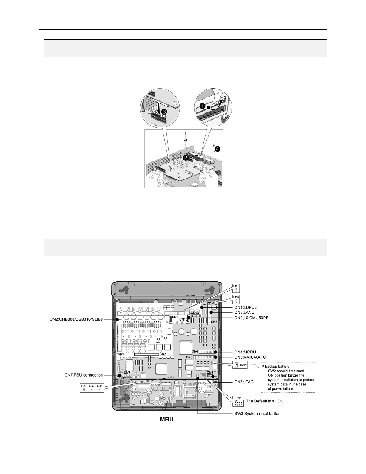
2.3 MBU (Main Board Unit).....................................................................................................7
2.3.1 Modular Jack (MJ1 – MJ3) Pin Assignment............................................................................. 9
2.3.2 Switch 1 Functions.................................................................................................................. 10
2.4 Installation of the CO Line & Extension Board............................................................11
2.4.1 CHB308 (3 CO Line and 8 Hybrid Interface Board) [not available in AR-CKSU].................. 11
2.4.2 CSB316 (3 CO and 16 SLT Interface Board) [not available in AR-CKSU]............................ 12
2.4.3 SLIB8 (8 SLT Interface Board) [not available in AR-CKSU] .................................................. 13
2.5 Other Board Installation .................................................................................................14
2.5.1 VMIU / AAFU (Voice Mail Interface Unit /Auto Attendant Function Unit)............................... 14
2.5.2 LANU (LAN Interface Unit) ..................................................................................................... 14
2.5.3 MODU (Modem Function Unit) ............................................................................................... 15
2.5.4 DPU2 (Two Door Phone Unit) ................................................................................................ 15
2.5.5 CMU50PR (Call Metering-50Hz and Polarity Reversal Detection Unit) ................................ 16
2.6 Terminal Connection and Wiring Method.....................................................................17
2.6.1 DKT/DSS Connection ............................................................................................................. 17
2.6.2 SLT Connection ...................................................................................................................... 17
2.6.3 Connecting Additional Terminals............................................................................................ 18
3 STARTING THE ARIA SOHO ............................................................................19
3.1 Before Starting the ARIA SOHO System ......................................................................19
3.2 Basic Programming ........................................................................................................19
3.2.1 DKT Admin Programming....................................................................................................... 19
3.2.2 How to enter the Admin Programming Mode ......................................................................... 21
3.2.3 Pre-Programming.................................................................................................................... 22
3.3 How to get incoming Call ...............................................................................................28
3.3.1 Ring Assignment to Station .................................................................................................... 28
3.3.2 DISA(Direct Inward System Access)...................................................................................... 29

ARIA SOHO Quick Start Guide
II
3.3.3 VMIU Recording for DISA....................................................................................................... 30
3.3.4 Attendant Assignment............................................................................................................. 30
3.4 How to access outgoing Call .........................................................................................31
3.5 Call Transfer.....................................................................................................................32
3.6 Pickup (Direct/Group).....................................................................................................33
3.6.1 Direct Pickup ........................................................................................................................... 33
3.6.2 Group Pickup .......................................................................................................................... 33
3.6.3 Programming for Pickup Group .............................................................................................. 34
3.7 INT MOH Type..................................................................................................................34
4 TROUBLESHOOTING........................................................................................35

ARIA SOHO Quick Start Guide
1
1 S
SY
YS
ST
TE
EM
M
O
OV
VE
ER
RV
VI
IE
EW
W
1.1 System Connection Diagram

ARIA SOHO Quick Start Guide
2
1.2 System Components
BASIC KSU
ITEM OPTION BOARD DESCRIPTION
KSU Key Service Unit
PSU Power Supply Unit
MBU Main Board Unit (3CO, 8DKT/1DKT and 7SLT)
CO and Extension Boards CO Line and DKT/SLT interface boards (CHB308,
CSB316, SLIB8)
Main Board
Other Boards VMIU, AAFU, LANU, MODU, DPU2, CMU50PR can
be installed
3CO Lines and 8 Hybrid Interface Board
CHB308
CMU50PR Call Metering (50Hz) and Polarity Reversal Detection
Unit (3 channels)
3 CO Lines and 16 SLT Interface Board
CMU50PR Call Metering (50Hz) and Polarity Reversal Detection
Unit (3 channels)
CSB316
SLU8 8 SLT Interface Unit Installed on CSB316 as a default
CO Line and
Extension
Boards
[not
available in
AR-CKSU]
SLIB8 8 SLT Interface Board
VMIU Voice Mail Interface Unit, 4 channels
AAFU Auto Attendant Function Unit, 4 channels
LANU LAN Interface Unit (10 base-T only)
MODU MODEM unit (33Kbps)
DPU2 2 Door Phone interface Unit
Other
Boards
CMU50PR Call Meeting (50Hz) and Polarity Reversal Detection
Unit (3 channels)

ARIA SOHO Quick Start Guide
3
2 I
IN
NS
ST
TA
AL
LL
LA
AT
TI
IO
ON
N
2.1 KSU Installation
2.1.1 Unpacking
Open the box and verify that the items shown in Figure 2.1 are included:
Key service unit
Mounting template
CD manual Quick Start Guide
Power cord
Battery cable
Tie cable Anchor plug Screw Fuse
FIGURE 2.1 CARTON CONTENTS

ARIA SOHO Quick Start Guide
4
2.1.2 Opening and Closing the Front Cover
2.1.2.1 Opening the Front Cover
1. Open the Cord cover and turn the screws counter-clockwise to loosen as shown in Figure 2.2.
2. Lift the front cover in the direction of the arrow as shown.
FIGURE 2.2 OPENING THE FRONT COVER
2.1.2.2 Closing the Front Cover
1. Insert the front cover into the slot on the KSU.
2. Then put the front cover down on the KSU in the direction of the arrow.
3. Turn the screws clockwise to tighten and close the Cord Cover.

ARIA SOHO Quick Start Guide
5
2.1.3 Frame Ground Connection
It is very important that the frame of the ARIA SOHO System is grounded:
1. Turn the grounding screw counter clockwise to loosen, as shown in Figure 2.3.
2. Insert the grounding wire and tighten the screw.
3. Then connect the grounding wire to an appropriate ground source (refer to Caution).
To earth
FIGURE 2.3 GROUNDING THE KSU
CAUTION
For ground wire, green-and-yellow insulation is required and the cross-sectional area of the conductor
must be more than UL 1015 AWG#18 (1.0mm)). It is recommended that the ground wire is shorter than
1m (3.28ft). We do not provide the ground wire.
2.1.4 External Backup Battery Installation
In case of power failure, the external backup batteries automatically maintain uninterrupted power for the ARIA SOHO
System. The external batteries must provide 24V DC; this is generally accomplished by connecting two 12V batteries
in a series arrangement as shown:
FIGURE 2.4 EXTERNAL BACKUP BATTERY INSTALLATION
CAUTION
It is recommended to use an external backup battery fuse (5A @250V) between the battery and the
System.
Recommended battery capacity is 24V/10AH MF; the ARIA SOHO System should be able to operate
more than 3 hours with batteries that are in good condition.
Carefully check the battery polarity with cable colors (Red and Blue) when connecting the battery to the
System.

ARIA SOHO Quick Start Guide
6
2.1.5 KSU Mounting
1. Install 3 anchor plugs in the wall using the mounting template included for accurate placement
(Figure 2.5).
2. Insert the 3 included screws to 3 anchor plugs.
3. Hook the KSU onto the screws, making sure that the System slides down securely (Figure 2.6).
FIGURE 2.5 MOUNTING TEMPLATE
FIGURE 2.6 KSU WALL MOUNTING
NOTE
ㅡ
Be careful not to drop the KSU.

ARIA SOHO Quick Start Guide
7
2.2 Board installation
To install the Board, perform the following Steps:
1. Before inserting the Board, remove the dummy slot as shown in #1 of Figure 2.9.
2. Holding the board as shown in #2 of the diagram, carefully insert the Board in the direction of the
arrow so that the Board securely engages with the connector (CN2) on the main board (#3).
FIGURE 2.7 BOARD INSTALLATION
CAUTION
Power must be turned OFF before board installation.
Insert boards carefully to avoid bending connector pins (male pins on MBU) and board damage from
power shortage caused by misaligning.
2.3 MBU (Main Board Unit)
The Main Board Unit (MBU) controls communication between the peripheral interfaces, supervises all resources in
the system, controls the gain adjustment of the PCM signal, generates the System tones, and manages System call
processing.
FIGURE 2.8 MBU
NOTE
ㅡ
When AC Power was failed, the last SLT port on MBU will be connected to CO1 automatically.

ARIA SOHO Quick Start Guide
8
The MBU is installed in the KSU and provides various kinds of connectors RJ11 modular jacks for the connection of
peripheral boards and miscellaneous functions (refer to Figure and Table).
FIGURE 2.9 MBU CONNECTION PORTS
CONNECTOR, MODULAR JACK AND SWITCH FUNCTIONS
SWITCH/CONNECTOR FUNCTIONS REMARK
CN1 KSU Connection 50Pins
CN2 CO and Extension Board(CHB308/CSB316/SLIB8) installation 50Pins
CN3 LANU Installation 32Pins
CN4 MODU Installation 20Pins
CN5 VMIU/AAFU Installation 32Pins
CN9 & CN10 CMU50PR Installation 6 & 8Pins
CN13 DPU2 Installation 16Pins
CN6 JTAG Port for Emulator For Test
CN7 PSU Connection (+5V, -5V, +30V) 7Pins
CN8 RS-232C Port Connection 9Pins
MJ1 3 CO Lines Connection 3Arrays
MJ2 8 DKTs or 1 DKT and 7 SLTs Connection 8Arrays
MJ3 Alarm Sensor and External Relay Contact 1Array
MJ4 USB Connection(USB Type B Connector) Slave Mode
PJ1 (Red) External MOH Connection
PJ2 (Blue) External PAGE Connection
SW1 4 Poles DIP Switch for Software Usage Default = All ON
SW2 Lithium Battery ON/OFF Switch for Memory and RTC Back Up Default = OFF
SW3 System Reset Button

ARIA SOHO Quick Start Guide
9
2.3.1 Modular Jack (MJ1 – MJ3) Pin Assignment
2.3.1.1 MBU MJ1 (CO)
MBU MJ1–1,2,3
Connector PIN Number NO Signal Name
1,2 N/A
3,4 CO-T, CO-R
RJ11
5,6 N/A
2.3.1.2 MBU MJ2 (Extension)
MBU MJ2-1 (DKT ONLY)
CONNECTOR PIN NUMBER NO SIGNAL NAME
1 N/A
2 DKT-T
3,4 Reserved
5 DKT-R
RJ11
6 N/A
MBU MJ2–2,3,4,5,6,7,8
CONNECTOR PIN NUMBER NO SIGNAL NAME
1 N/A
2 DKT-T
3,4 SLT-T, SLT-R
5 DKT-R
RJ11
6 N/A
NOTE
ㅡ
When installing DKT or SLT on Hybrid Ports, (MJ2-2,3,4,5,6,7,8), keep the above pin assignment.
Otherwise the DKT or SLT will not operate normally.
TERMINAL DKT
CONNECTOR PIN NUMBER NO SIGNAL NAME
1 N/A
2 RING
3,4 Reserved
5 TIP
RJ11
6 N/A
TERMINAL SLT
CONNECTOR PIN NUMBER NO SIGNAL NAME
1,2 N/A
3,4 TIP, RING
RJ11
5,6 N/A

ARIA SOHO Quick Start Guide
10
2.3.1.3 MJ3 Pin Assignment (Alarm Detection and Relay Contact)
MJ3
CONNECTOR PIN NUMBER NO SIGNAL NAME
1 N/A
2 ALARM-T
3 ALARM-R
4 Relay-T
5 Relay-R
RJ11
6 N/A
MJ4 PIN ASSIGNMENT (USB)
CONNECTOR PIN NUMBER NO SIGNAL NAME
1 External Power (+5V)
2 D-
3 D+
USB Type B
4 GND
2.3.2 Switch 1 Functions
SWITCH FUNCTION OFF ON (DEFAULT)
1-1 Administration Programming Access Disable Enable
1-2 Command/Event Trace (Software Testing) Enable Disable
1-3 Simplified Message Desk Control (SMDI – Voice Mail) SMDI ON SMDI OFF
1-4 Database Default on Power Up Disable Enable
Before programming the System, switch 1-4 should be ON and then power cycle OFF and ON to initialize the default
System database. Once the database has been initialized, switch 1-4 should be placed in the OFF position to protect
the database.
After putting the SW2 lithium battery switch ON to protect the RAM/RTC data, install the option boards to the MBU.
NOTE
The SW2-DIP switch should be turned ON to protect the System database in case of power failure.
As needed, replace the batteries with the same or equivalent type recommended by the manufacturer; the
System will not function normally if the battery is incorrectly replaced.
Be sure to dispose of used batteries according to manufacturer instructions and/or local government
regulations.
The 4th pole of SW1 should be OFF to protect the features being programmed in Admin programming after
the System power up and initialization.

ARIA SOHO Quick Start Guide
11
2.4 Installation of the CO Line & Extension Board
2.4.1 CHB308 (3 CO Line and 8 Hybrid Interface Board) [not available in AR-CKSU]
The CHB308 can be installed on the CHB308/CSB316/SLIB8 (CN2) connector of the MBU, and provides 3 CO/PBX
Loop Start CO Line interfaces that support Pulse/DTMF signaling. Each interface contains ring and loop current
circuits, A/D and D/A conversions, and pulse signaling circuitry.
FIGURE 2.10 CHB308
2.4.1.1 Modular Jack (MJ1-MJ2) Pin Assignment
CHB308 MJ1 – 1,2,3
CONNECTOR PIN NUMBER NO SIGNAL NAME
1,2 N/A
3,4 CO-T, CO-R
RJ11
5,6 N/A
CHB308 MJ2 – 1,2,3,4,5,6,7,8 (EXTENSION)
CONNECTOR PIN NUMBER NO SIGNAL NAME
1 N/A
2 DKT-T
3,4 SLT-T, SLT-R
5 DKT-R
RJ11
6 N/A
2.4.1.2 Add-On Board CMU50PR(Call Metering-50 Hz & Polarity Reversal Detection unit)
The CMU50PR provides 3 channels Call Metering detection for 50Hz and provides 3 channels of Polarity Reversal
Detection for call metering. It can be installed on the MBU, CHB308, or CSB316.

ARIA SOHO Quick Start Guide
12
2.4.2 CSB316 (3 CO and 16 SLT Interface Board) [not available in AR-CKSU]
The CSB316 can be installed on the CHB308/CSB316/SLIB8(CN2) connector of the MBU.
FIGURE 2.11 CSB316
2.4.2.1 Modular Jack Pin Assignment
CSB316 MJ1 – 1,2,3
CONNECTOR PIN NUMBER NO SIGNAL NAME
1,2 N/A
3,4 CO-T, CO-R
RJ11
5,6 N/A
CSB316 MJ2 – 1,2,3,4,5,6,7,8
CONNECTOR PIN NUMBER NO SIGNAL NAME
1 N/A
2 SLT-T
3,4 SLT-T, SLT-R
5 SLT-R
RJ11
6 N/A
NOTE
ㅡ
The CSB316 is shipped with 8 Terminal Blocks
FIGURE 2.12 TERMINAL BLOCK

ARIA SOHO Quick Start Guide
13
TERMINAL SLT
CONNECTOR PIN NUMBER NO SIGNAL NAME
1,2 N/A
3,4 TIP, RING
RJ11
5,6 N/A
2.4.2.2 Add-On Board CMU50PR (Call Metering-50Hz and Polarity Detection Unit)
The CMU50PR provides 3 Call Metering Detection for 50Hz and provides 3 channels of Polarity Reversal detection
for call metering. It can be installed on the MBU, CHB308, or CSB316.
2.4.2.3 Add-On Board SLU8 (8SLT Interface Unit)
The SLU8 provides 8 SLT interfaces and can be installed on only the CSB316.
It can be installed on CSB316 only as a default when shipped.
2.4.3 SLIB8 (8 SLT Interface Board) [not available in AR-CKSU]
The SLIB8 can be installed on the CHB308/CSB316/SLIB8(CN2) connector of the MBU, and provides 8 possible SLT
interfaces. It can generate FSK signals for outgoing Caller ID; DTMF signals for outgoing Caller ID.
FIGURE 2.13 SLIB8
2.4.3.1 Modular Jack Pin Assignment
SLIB8 MJ2 – 1,2,3,4,5,6,7,8
CONNECTOR PIN NUMBER NO SIGNAL NAME
1 N/A
2 Reserved
3,4 SLT-T, SLT-R
5 Reserved
RJ11
6 N/A

ARIA SOHO Quick Start Guide
14
2.5 Other Board Installation
2.5.1 VMIU / AAFU (Voice Mail Interface Unit /Auto Attendant Function Unit)
The Voice Mail Interface Unit (VMIU) can be installed on the VMIU/AAFU connector (CN5) of the MBU, and provides
the capability for System announcements, ACD/UCD announcements, and User Greetings.
FIGURE 2.14 VMIU
VMIU DESCRIPTION
ITEM VMIU AAFU
Channel 4 Channels 4 Channels
Max Record Time:
System Greeting (system announcement)
User Record Time
125 Min.
25 Min.
100 Min.
35 Min.
25 Min.
10 Min
Max. Number of User Voice Messages 800
NOTE
ㅡ
User greetings are stored in Nand Flash memory and will not be lost by System power OFF or reset.
MBU SW1-4 and SW2 control the protection of recorded messages.
2.5.2 LANU (LAN Interface Unit)
LAN Interface Unit (LANU) should be installed on the LANU connector (CN3) of the MBU and provides 1 LAN port of
10 Base-T networking. RJ45 Modular Jack, MJ1 is used to interface with a Wide Area Network (WAN) or PC. Two
LEDs are provided to indicate the operational state of the LAN port.
FIGURE 2.15 LANU

ARIA SOHO Quick Start Guide
15
2.5.3 MODU (Modem Function Unit)
MODU should be installed on the MODU connectors (CN4) of the MBU, and provides an analog modem connection.
It supports Bell, ITU-T, V.34, V.32BIS, V.90 Protocol at a speed rate of 300bps up to 33Kbps, and automatic rate
negotiation.
FIGURE 2.16 MODU
2.5.4 DPU2 (Two Door Phone Unit)
The Two Door Phone Unit (DPU2) should be installed on the DPU2 connector (CN13) of the MBU, and provides two
Door Phone interfaces and two Relay contacts for door opener.
FIGURE 2.17 DPU2
2.5.4.1 Modular Jack (MJ1-MJ2) Pin Assignment
DPU2 MJ1 (DOOR PHONE)
CONNECTOR PIN NUMBER NO SIGNAL NAME
1 N/A
2 DPH1-T
3 DPH1-R
4 DPH2-T
5 DPH2-R
RJ11
6 N/A

ARIA SOHO Quick Start Guide
16
DPU2 MJ2 (RELAY CONTACT)
CONNECTOR PIN NUMBER NO SIGNAL NAME
1 N/A
2 Relay 1-T
3 Relay 1-R
4 Relay 2-T
5 Relay 2-R
RJ11
6 N/A
TERMINAL LDP-DPB
CONNECTOR NO SIGNAL NAME
1,2 External switch pole
3 TIP
Screw type
4 RING
2.5.5 CMU50PR (Call Metering-50Hz and Polarity Reversal Detection Unit)
The Call Metering-50Hz and Polarity Reversal Detection Unit (CMU50PR) provides 3 Call Metering Detection circuits
for 50Hz and provides 3 channels of Polarity Reversal Detection for Call Metering or signaling. It can be installed on
MBU, CHB308 and CSB316.
FIGURE 2.18 CMU50PR

ARIA SOHO Quick Start Guide
17
2.6 Terminal Connection and Wiring Method
2.6.1 DKT/DSS Connection
The following illustrates how to connect the DKT and the DSS to your System:
FIGURE 2.19 DKT CONNECTION
FIGURE 2.20 DSS INSTALLATION AND CONNECTION
PIN ASSIGNMENT
CONNECTOR PIN NUMBER NO SIGNAL NAME
1 N/A
2 RING
3,4 Reserved
5 TIP
RJ11
6 N/A
2.6.2 SLT Connection
The following illustrates how to connect the SLT to your System:
FIGURE 2.21 SLT CONNECTION
PIN ASSIGNMENT
CONNECTOR PIN NUMBER NO SIGNAL NAME
1,2 N/A
3,4 TIP, RING
RJ11
5,6 N/A
Other manuals for ARIA SOHO
3
Table of contents
Popular Gateway manuals by other brands

Media5
Media5 Mediatrix 3000 Series Configuration notes

Mitsubishi Heavy Industries
Mitsubishi Heavy Industries Superlink SC-WBGW256 installation manual

InnoMedia
InnoMedia MTA 8328-1W Quick install guide

Multitech
Multitech RouteFinder RF550VPN user guide

Sunway
Sunway SMG Series user manual

Technica Engineering
Technica Engineering 1150 manual