LG LP-K2060CL/CA User manual

Package
Air Conditioner
SERVICE MANUAL
MODEL: LP-K2060CL/CA
LP-K3060CL/CA
LP-K3020CL/CA
LP-K4020CL/CA

Contents
Functions 3
Product Specifications (Cooling Model only) 5
Dimensions 6
Refrigeration Cycle Diagram 6
Wiring Diagram 7
Operation Details 9
Installation of Indoor, Outdoor Unit 14
Test Running 24
3-way Valve 26
Cycle Troubleshooting Guide 31
Electronic Parts Troubleshooting Guide 32
Electronic Control Device 33
Schematic Diagram 34
Exploded View and Replacement Parts List 35
–2–

–3–
Indoor Unit
Power Switch ON/OFF
Operation Mode Control
Indoor Fan Speed Control
Jet Cool
Energy Saving
Room Temperature control
Auto Operation
Soft Dry Operation Mode
Time Delay Safety Control
Fan Operation
AutoRestart
• Cooling, Auto, Soft Dry
• High, Low
• Speed Cooling operates super high fan speed in cooling mode
• Maintains the room temperature in accordance with the Setting Temp.
• Up: up to 30°C
• Down: down to 16°C
• The setting temperature, indoor fan speed and desired operation mode are automatically set.
• Intermittent operation of fan at low speed.
• Restarting is inhibited for approx. 3 minutes.
• Used to circulate room air without cooling.
• The power comes on again after a power failure.
Functions

–4–
• The setting temperature indoor fan speed and desired operation mode are automatically set.
• Intermittent operation of fan at low speed.
• Used to circulate room air without cooling.
• OFF Timer (1, 2, 3,......7 hour)
• Speed cooling operates super high fan speed in cooling mode.
• Airflow direction Auto-swing and Manual Contol.
• Up: up to 30°C
• Down: down to 16°C
• High, Low
Remote Control
Operation ON/OFF
Cooling Operation Mode
Auto Operation Mode
Sot Dry Operation Mode
Fan Operation
Timer Control
Jet Cool
Energy Saving
Airflow Direction Control
Room Temperature Control
Indoor Fan speed control

Product Specifications (Cooling model only)
–5–
POWER SUPPLY Ø, V, Hz
COOLING CAPACITY Btu/hr
HEATING CAPACITY Btu/hr
(Incl. elec. Heater)
POWER INPUT COOLING W
HEATING W
RUNNING COOLING A
CURRENT HEATING A
MODEL
MAKER
TYPE
COMPRESSOR CAPACITY Btu/hr
INPUT (KW)
LRA A
NOISE LEVEL INDOOR dB(A)
OUTDOOR dB(A)
AIR INDOOR
CFM/CMM
CIRCULATION OUTDOOR
CFM/CMM
REFRIGERANT (R-22) OZ(kg)
HEAT INDOOR R/C/FPI
EXCHANGER OUTDOOR R/C/FPI
FAN INDOOR TYPE
OUTDOOR TYPE
ROOM TEMPERATURE CONTROL
WIDTH
INDOOR HEIGHT inch(mm)
DEPTH
WIDTH
OUTDOOR HEIGHT inch(mm)
DEPTH
NET WEIGHT INDOOR Ib(kg)
OUTDOOR Ib(kg)
CONNECTIONS LIQUID inch(mm)
GAS inch(mm)
1, 220-240, 50
27,800
-
3,000
-
14.5
-
H25B35QABHA
BRISTOL
RECIPRO
30,200
2.83
85
48
58
670/19
2,046/58
63.5(1.8)
3/22/18
2/24/18
SIROCO
PROPELLER
MICOM CONTROL
19.68(500)
70.86(1800)
12.59(320)
34.25(870)
25.78(655)
12.59(320)
88.18(40)
138.6(63)
3/8"(Ø9.52)
5/8"(Ø15.88)
1, 220,60
36,000
-
3,500
-
17
-
CR38K6-PFV-502
COPELAND
RECIPRO
38,200
3.52
102
52
62
741/21
2,225/63
84.6(2.4)
3/22/18
2/30/18
SIROCO
PROPELLER
MICOM CONTROL
19.68(500)
70.86(1800)
12.59(320)
34.25(870)
31.49(800)
12.59(320)
88.18(40)
147.7(67)
3/8"(Ø9.52)
5/8"(Ø15.88)
ITEMS UNIT
MODEL
LP-K4020CL/CALP-K3060CL/CA
D
I
M
E
N
S
I
O
N
S

Dimensions
Indoor Unit
Air Outlet Vent
Remote Signal
Receptor
Air Intake Vent
Air Intake Vent
(Rear)
Air Outlet
Vent
INDOOR UNIT OUTDOOR UNIT
HEAT
EXCHANGER HEAT
EXCHANGER
COMPRESSOR
GAS SIDE
LIQUID SIDE
COOLING
HEATING
REVERSING
VALVE
CHECK VALVE
CAPILLARY TUBE
CAPILLARY TUBE
BY PATH CAPILLARY TUBE
–6–
Outdoor Unit
Refrigeration Cycle Diagram

Wiring Diagram
(1) • LP-K3060CL/CA
LP-K3020CL/CA
INDOOR UNIT OUTDOOR UNIT
DISPLAY
PCB ASM
CA MODEL
MAIN PCB ASM
RY-S/HIGH
RY-AIRC
BK
CN-DISP(1) CN-DISP(2)
CN1 CN2
ROOM
TH
DOOR S/W
BK RD
BK
WH
RD
HVB
ASM A/CL
UNIT
OR BR YL
Ci
WH
BK
BL
RD
GN/YL
RY-COMP
RY-SYNC
(250V/3A) SM
EVAP
TH
RY-HIGH
RY-MID
RY-LO
RD
GN/YL
WH
BK
BK
GN/YL
BL
BR
FUSE
CN-GND
GN/YL
P/No.; 3854A90012Q
CIRCUIT DIAGRAM
FAN
MOTER
COMP.
POWER
RELAY
POWER INPUT
HIDDEN LINE: FIELD WIRING
(CONNETING CABLE)
CAPACITOR
BR
BR
BR
BL
BR
OR
BR
BL
BL
TERMINAL
BLOCK(6P)
1
F1
F2
234
GN/YL
5 6
BL BK
BK
BL
BL
BK
BK
BR
CR
S
RD BL
OR YL
GN/YL
2 6
4 8
0
1
CAPACITOR
FAN
MOTOR
NOTE
BL
BK
BR
RD
OR
WH
YL
GN/YL:GREEN/YELLOW
BLUE
BLACK
BROWN
RED
ORANGE
WHITE
YELLOW
:
:
:
:
:
:
:
–7–

Wiring Diagram
(2) Indoor Unit
• LP-K4020CL
(3) Outdoor Unit
• LP-K4020CL
–8–
NOTE
SM
Ci
FMi
THi
Co
FMo
Cr
52C
Tmo1,2
CM
63H
SYNCHRONOUS MOTOR
CAPACITOR FOR FAN(INDOOR)
INDOOR FAN MOTOR
THERMISTOR FOR INDOOR TEMP.
CAPACITOR FOR FAN(OUTDOOR)
OUTDOOR FAN MOTOR
RUN CAPACITOR FOR COMP.
MAGNATIC CONTACTOR
TERMINAL BLOCK(OUTDOOR)
COMPRESSOR MOTOR
HIGH PRESSURE SWITCH
NOTE
RD
BL
BK
WH
GY
RED
BLUE
BLACK
WHITE
GRAY
:
:
:
:
:
BR
VT
GN
OR
GN
BROWN
VIOLET
GREEN
ORANGE
GREEN/YELLOW
:
:
:
:
/YL :
FIELD WIRING
INDOOR UNIT CIRCUT DIAGRAM
DISPLAY
PCB ASM
RY-SH OR
BR YL
Ci
WH
BK
BL
RY-COMP
RY-SYNC
(250V 3A) SM
FMi
THi
RY-H
RY-MID
BK
WH
RD
BK
WH
RD
FUSE
CONNECT TO
OUTDOOR UNIT
NOTE
CM
Co
FMo
Cr
52C
Tmo1,2
63H
COMPRESSOR MOTOR
CAPACITOR FOR FAN
(OUTDOOR)
OUTDOOR FAN MOTOR
RUN CAPACITOR FOR COMP.
MAGNATIC CONTACTOR
TERMINAL BLOCK(OUTDOOR)
HIGH PRESSURE SWITCH
RD
BL
BK
WH
GY
RED
BLUE
BLACK
WHITE
GRAY
:
:
:
:
:
BR
VT
GN
OR
GN
BROWN
VIOLET
GREEN
ORANGE
GREEN/YELLOW
:
:
:
:
/YL :
FIELD WIRING
OUTDOOR UNIT CIRCUT DIAGRAM
CONNECT TO
INDOOR UNIT
P/No.: 3854AP2708P
CM
POWER SUPPLY
1ø, 220V, 60Hz
Tmo1
1 2 3 4 5 6
L1
T1 L2
T2 52C
B
A
FMo
OR
RD
WH
BR
BK
BK
WH
WH
Tmo2
RD
RDWHBK
WH
GN/YL
RD
RD
BK
BK
63H
FUSE
250V
5 A
WH
RSC
WH
PTCR
Cr
BK
BK YL
Co
FUSE
250V
5 A
BR
OR
(CAUTION)
1. This product is only for 1ø, 220V, 60Hz.
2. "Check List" before test run.
1st: Reconfirm the wiring connecting of compresssor,
outdoor unit motor.
2st: Fasten the screw of Terminal block
'Tmo1' once more.

–9–
(1) The function of main control
1. Time Delay Safety Control
ƒU3min¡ƒ The compressor is ceased for 3 minutes to balance the pressure in the refrigeration cycle.
(Protection of compressor)
ƒU3sec¡ƒ The indoor fan is ceased for 3 seconds to prevent relay noise.
(Protection of fan relay and micro chip)
ƒU30sec¡ƒThe 4-way valve is ceased for 30 sec. to prevent the refrigerant-gas abnormal noise when the Heating
operation is OFF or switched to the other operation mode.
2. Airflow Direction Control
ƒUThis function is to swing the louver left and right automatically and to set it at the desired position.
ƒUThe procedure is as the following.
1st : Press the ON/OFF Button to operate the product.
2nd : Press the Airflow Direction Control Button to swing the louver left and right automatically.
(Remote controller)
3rd : Repress the Airflow Direction Control Button to set the louver as the desired position.
(Remote controller)
ƒU8HP Model don't have this function.
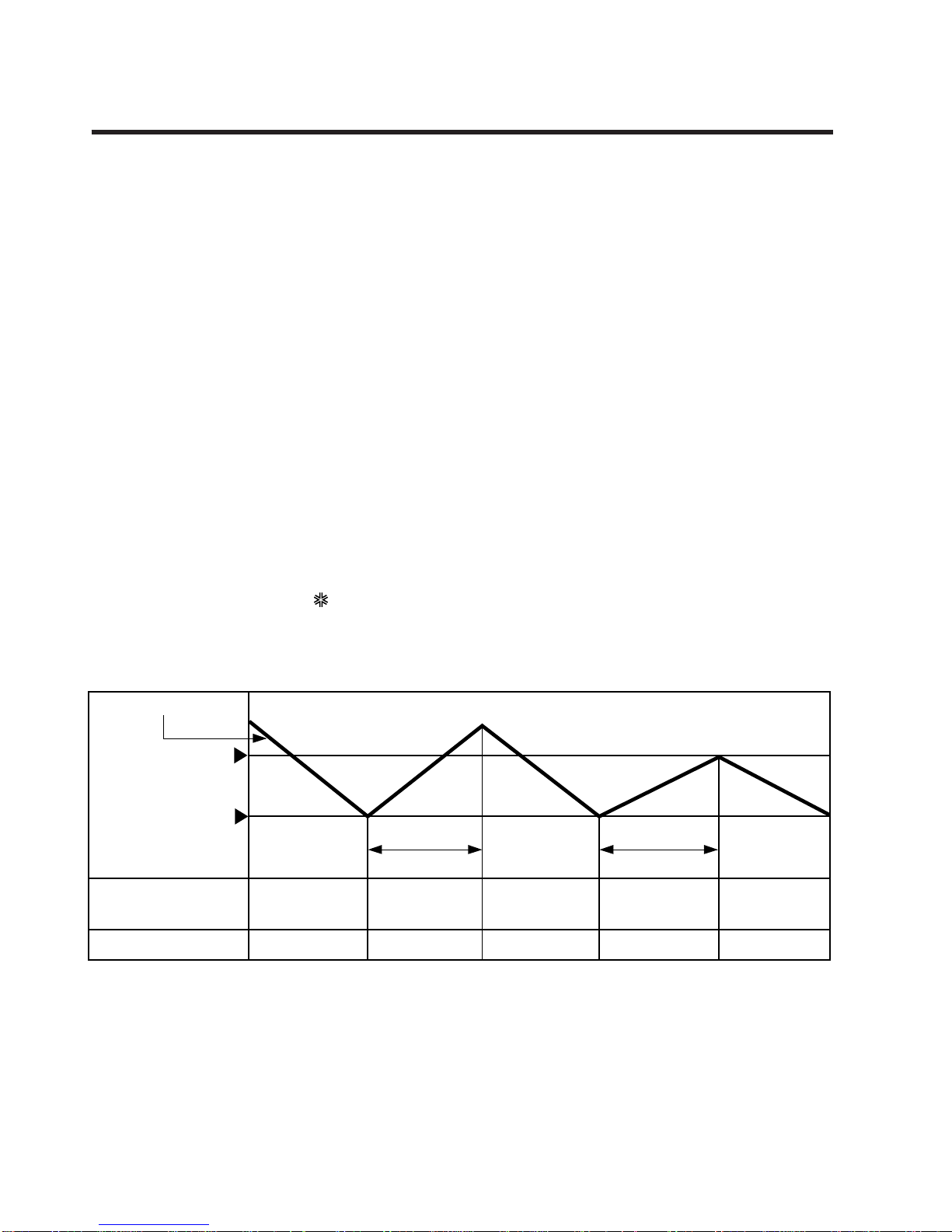
3. Cooling Mode Operation
ƒUWhen selecting the Cooling( ) Mode Operation, the unit will operate according to the setting by the
controller and the operation diagram is as following.
Intake Air temp.
Setting Temp. +1°C
(Compressor ON)
Setting Temp. -1°C
(Compressor OFF)
Indoor Fan Speed Selecting
fan speed Selecting
fan speed Selecting
fan speed Selecting
fan speed Selecting
fan speed
3 minutes
More than 3 minutes
More than
Compressor ON OFF ON OFF ON
Operation Details

–10–
4. Auto Operation (Cooling Model only)
ƒUThe operation procedure is as following.
ƒUAuto Operation for Cooling
Press Start/Stop Button
Select Auto Operation Mode
Check the Room temperature
Operation Condition Intake-air Temperature Setting temperature Fan speed
Over 26°C 25°C
Over 24°C~below 25.5°C Intake air -1.0°C
Over 22°C~below 23.5°C Intake air -0.5°C
below 21.5°C Intake air Temperature(18°C, MAX)
When Switch to
Auto Operation
Controlled
by Fuzzy logic
Intake Air Temp.
Indoor Fan Speed
Compressor ON OFF
Fuzzy Speed
ON OFF
Setting Temp. +1°C
(Compressor ON)
Setting Temp. -1°C
(Compressor OFF)
3 minutes
More than 3 minutes
More than
5. Off Timer Function
This function is to set the time of stopping the unit operation.
The procedure is as the following.
1st: Press the timer set button on the Remocon.
2nd: The buzzer sounds and then the display window shows the Off-Time to be set as
- The Off-Time is shifted as the following by each press.
- If you select ' ', the Off-Timer function will be cancelled.
- During Off-Timer Operation, if you repress the timer set button, the rest time will be displayed.
....

–11–
9. Child Lock function
This function is to operate Air conditioner only by Remocon.
The procedure is as the following
1st: Press the 2 buttons of the temperature control simultaneously, to raise-to lower on the Display Panel of the
product for more 3 seconds.
2nd: The buzzer sounds and then the window of Display Panel shows
CCLL
(CL) mark.
3rd: To release this function, the reverse again the operating procedure could be done.
❈During this function is operating, any buttons of Display Panel don't work. But it is possible to operate with
Remote controller.
7. Protection of the evaporator pipe from frosting
• Compressor and outdoor fan stop when indoor pipe temperature is below -2°C and restart at the pipe temperature
is above 12°C.
8. Air Purifying Operation(CA Model only)
6. Soft Dry Operation Mode
• During Soft Dry Operation, the compressor ON temperature is the setting temperature plus 2°C, the compressor
OFF temperature is the setting temperature minus 1°C.
• When the room temperature rises over the compressor ON temperature, the operation mode is switched to the Cool-
ing mode.
• When the room temperature falls between the compressor ON temperature and OFF temperature, the operation
mode is switched to the Soft Dry Operation.
• The operation diagram is shown below.
Intake Air Temp.
Indoor Fan Speed LOW
Selecting
fan speed Selecting
fan speed
LOW LOW LOW LOW
Compressor OFFON ONON OFF OFF ON
LOW
OFF
Setting Temp. +2°C
(Compressor ON)
Setting Temp. -1°C
(Compresso OFF)
Operation
Cooling Cooling
operation
Dry operation
3 min. 3 min.
10 min.
maximum
7 min. maximum
10 min.
Mode Selecting
Operating Mode
Fan Speed Outdoor OFF
Initial Starting
of Air purifying
Operation
- Low at the initial
- But could be
switched to Med.
Hi OFF
- Outdoor not operating
- Fan operating + Air puri-
fying operating
Repress Air
purifying
Button or
ON/OFF
Button
When switched
to Air purifying
operation
Selecting Speed
of Main Operating
Mode
ON or OFF
depend on
main operat-
ing
- Outdoor operating
- Main Operating +
Air purifying operating

10. Alarm mode display / only displayed while operating.
CCOO
: The sensor for sensing room temperature is open or short.
11. Jet Cool
❏During the JET COOL function at any moment, the A/C starts to blow the cool air at extremely high speed
setting the room temp. automatically to 18°C. It is especially used to cool the room temp. in the shortest time
in a hot summer.
In heat pump mode or neuro fuzzy mode however, the JET COOL function is not available.
❏You can select this function during the operation of Cooling/ Soft Dry/ Auto/ Fan.
❏When it is selected, JET COOL lamp is on immediately and fan speed graphic(red) is on 3 times off.
❏Possible to select or cancel using JET COOL key.
❏To cancel the JET COOL Mode, press the JET COOL button again or the Fan Speed button or the Room
Temperature Setting button and the unit will operate in high Fan speed on Cooling mode(set up to 18°C).
❏During the operation when it stops and runs again setting up is high fan speed on cooling mode(set up to
18°C).
12. Energy Saving
➀If setting temperature of starting energy saving operation is under 22°C, first, setting temperature it up to
22°C and perform energy saving operation.
➁After energy saving operation starts, if adaptation time of the human body pass from the point which room
temperature and setting temperature meet together, increase setting temperature 1°C more.
➂If it doesn't satisfy number ➀even in 50 minutes from the start of energy saving operation, increase 1°C.
➃After increasing setting temperature 1°C more by number ➀, ➁, perform number ➁, ➂again, if setting tem-
perature goes up to 25°C, maintain this temperature.
➄If setting temperature goes down to under 25°C, during the operation, do number ➁, ➂, ➃again.
13. AUTO RESTART
In case the power comes on again after a power failure, Auto Restarting Operation is the function to operate
procedures automatically to the previous operating conditions.
In case the air conditioner does not receive any signal from the remote control, it will turn off automatically after
7 hours.
–12–
Setting energy
saving operation Setting temp.
23˚C
21˚C
22˚C
23˚C
24˚C
25˚C
26˚C
27˚C
Setting temp.
24˚C Setting temp.
25˚C maintains setting temp.
25˚C
28min.
50min. 50min. 50min.
35min. 47min.

14. Function for test operation
1) Outline of Operation
- This is for checking the condition of installation during the installation, and it is operated by cooling, Fan
speed is high, comp. on, and Auto air flow operations without setting temperature.
2) Operation or Cancel
- Do test operation, if you push ON/OFF button and the down room temperature checking button over 3 sec-
onds at the same time.
- During the operation, if you push the stop button or push ON/OFF button and the down room temperature
checking button over 3 seconds at the same time, the test operation will be cancelled and unit come to rest.
- During the operation, if you input remocon key or key on Display panel, it performs its duties.
3) Function
- It operates cooling, fan speed is high, comp. on for 18 ± 1 minutes, regardless of room temperature.
- After 18 ± 1 minutes of operation, it becomes off itself.
- During the operation, signal 8888stands for "LLoo"
–13–

1. Selection of the best location
1) Indoor unit
• There should not be any heat source or steam
near the unit.
• There should not be any obstacles to prevent the
air circulation.
• A place where air circulation in the room will be
good.
• A place where drainage can be easily obtained.
• A place where noise prevention is taken into con-
sideration.
• Do not install the unit near the door way.
• Ensure the spaces indicated by arrows from the
wall, ceiling, fence, or other obstacles.
2) Outdoor unit
• If an awning is built over the unit to prevent direct
sunlight or rain exposure, be careful that heat
radiation from the condenser is not restricted.
• There should not be any animals or plants which
could be affected by discharged hot air.
• Ensure the space indicated by arrows from the
wall, ceiling, fence, or other obstacles.
–14–
Installation of Indoor, Outdoor Unit
50cm
50cm
50cm
100cm
5cm
5cm
40cm
100cm
A
B
Indoor unit
Outdoor unit
3) Piping length and the elevation
Cooling Only Model
5/8" 3/8" 30 20
28K/30K/40K
PIPE SIZE
MODEL
GAS SIDE LIQUID SIDE
Max.
Length
A (m)
Max.
Elevation
B (m)

–15–
2. Indoor Unit installation
¥LThe mounting floor should be strong and solid
enough to prevent it from vibration.
¥MDrill the piping hole with 70mm diameter hole-
core drill at either the right or the left of indoor
unit. The hole should be sightly slant to the out-
door side.
¥NInsert the plastic tube through the hole.
¥OCut the extruded outside part of the plastic tube,
if necessary.
3. Outdoor unit Installation
¥LInstall the outdoor unit on the concrete or any
solid base securely and horizontally by securing
it with bolts (Ø12mm) and nuts.
¥MIf there is any vibration transmitted to the build-
ing, mount the rubber underneath the outdoor
unit.
4. Refrigerant amount
Before shipment, this air conditioner is filled with
the rated amount of refrigerant including additional
amount required for air-purging, subject to 5m pip-
ing length. (The rated amount of refrigerant is indi-
cated on the name plate.) But when the piping
length exceeds 5 meters, additional charge is
required according to the following table.
(Unit: g)
Example) 28K/30K/40K
In case of 10m long pipe(one-way), the amount of
refrigerant to be replenished is:
(10 - 5) x 30 = 150g
Wall
Core Drill
Tilt
Cut if necessary
More than 15mm
Wall
Plastic tube
(Bushing)
INSIDE OUTSIDE
200mm
70mm 70mm
90mm
MODEL
28K/30K/40K
(BTU/h)
REFRIGERANT CHARGE
30 per 1m

–16–
■Installation Method
No. Installation works Descriptions
1 Preparation of tools and installation parts Preparation of installation
2 Flaring the pipes To insert the flare nuts, mounted on the
connection parts of both indoor and
outdoor unit, onto the copper pipes.
3 Pipe bending To reduce the flow resistance of refrigerant.
4 Connection of installation parts Connection of long piping
(elbows, socket etc)
5 Tighten the flare nut (outdoor) Connecting the pipings of the outdoor unit.
6 Blowing the pipings To remove dust and scale in working.
7 Tighten the flare nut (indoor) Connecting the pipings of the indoor unit.
8 Check a gas-leakage of the connecting
part of the pipings.
9 Air purging of the piping and indoor unit The air which contains moisture and which
remains in the refrigeration cycle may cause a malfunction on the
compressor
10 Open the 3-way (liquid side) and
3-way (gas side) valves.
11 Form the pipings To prevent heat loss and sweat
12 Checking the drainage (indoor unit) To ensure if water flow drain hose of indoor unit.
13 Connecting the cable between outdoor Preparation of the operating
and indoor unit
14 Connecting the main cable to outdoor unit
15 Supply the power to the crankcase heater To prevent the liquid back to the compressor.
(Before the operating the unit) (Heat pump only)
16 Cooling operation
(Use the remote control or display of the
indoor unit)
1. Procedure

–17–
2. Preparation of installation parts and tools
No. Installation Parts, Tools Use
1 Flaring tool (Ø 6,35 - Ø 19,05) Flaring the pipes
2 Remear Remove burrs from cut edges of pipes.
3 Pipe cutter (MAX 35mm Copper pipe) Cutting the pipings
4 Wrench (H5, H4 hexagonal wrench) To open the service valve
5 Pipe bender Bending the pipings
6 Leak detector Check a gas-leakage of connecting part
of the pipings
7 Manifold gauge
To measure the pressure, to charge the refrigerant
8 Charge-nipple To connect the bombe
9 Vacuum pump To remove the air in the pipe.
10 Charge cylinder balance To measure the refrigerant amount
11 Bombe (Freon-22) Gas charge
Air purge
Cleaning the pipe
12 Spanner To tighten the connecting parts of the pipings
13 Monkey spanner
14 Driver( , )
15 Benchi (150mm) Cutting the wires
16 Tapeline To measure the length
17 Core drill
To make holes through the concrete wall and blocks
18 Voltmeter, Amperemeter, Clampmeter To measure the current and voltage
19 Insulation resistance tester To measure the insulation resistance
20 Glass thermometer
To measure the intake and outlet air temperature of the indoor unit
21 Copper tubes To use the connecting pipings
22 Insulation material To cover the connecting pipings
23 Tape To finish the connecting pipings
24 Electrical Leakage Breaker To shut off the main power
25 Cable
To connect the cable from outdoor unit to indoor unit
26 Drain hose sockets, elbows To remote the condensing water

–18–
1. Preparation of piping
¤Cut the pipes and the cable
• Use the accessory piping kit or the pipes
purchased locally.
• Measure the distance between the indoor and
the outdoor unit.
• Cut the pipes a little longer than measured
distance.
• Cut the cable 1.5m longer than the pipe length.
¤ŁRemove burrs.
• Remove burrs from cut edges of pipes.
• Turn the pipe end down to avoid the metal pow-
der entering the pipe.
Caution:
If burrs are not removed, they may cause a gas
leakage.
¤ØFlaring the pipes.
• Insert the flare nuts, mounted on the connection
ports of both indoor and outdoor unit, onto the
copper pipes. Some refrigerant gas may leak,
when the flare nuts are removed from the indoor
unit, as some gas is charged to prevent the
inside of the pipe from rusting.
• Fit the copper pipe end into the Bar of flare tool
about 0~0.5mm higher. (See illustaration)
• Flare the pipe ends.
¤ŒTape the flaring part to protect it from dust or
damages.
90°
Pipe cutter
Slanted Rough
Pipe
Point down
Reamer
Bar 0~0.5mm
Copper
pipe Clamp handle
Bar Handle
Yoke
Cone
Red arrow mark
4321
= Improper flaring =
Inclined CrackedSurface
damaged Uneven
thickness
■Piping of Indoor Unit

–19–
• Align the center of the pipings and suffciently tight-
en the flare nut with fingers.
• Finally, tighten the flare nut with troque wrench
until the wrench clicks.
When tightening the flare nut with troque wrench,
ensure the direction for tightening follows the arrow
on the wrench.
3. Precautions in bending
¤
If it is necessary to bend or stretch the tubing,
use the spring which is attached to the tubing in
stead of pipe bender.
• Please make a careful notice to make a smooth
line.
• Hold the tubing with your two hands closely and
then bend or stretch it slowly not to make any
crack.
• Remember that the radius (R) should not exceed
70mm (Refer to Fig. 1)
¤ŁDo not repeat the bending process to prevent the
tubing from cracking or crushing.
¤ØKeep in mind that the bending part should not be
cracked and make the radius (R) as long as possi-
ble (Refer to Fig. 2)`
PIPE SIZE TORQUE
3/8" 4.2 Kg.m
1/2" 5.5 Kg.m
5/8" 5.5 Kg.m
3/4" 6.5 Kg.m
Indoor unit tubing Flare nut Pipings
Torque wrench
Spanner
Spring
R70mm
(Fig. 1)
(Fig. 2)
R
2. Connection of piping
¤Move the indoor tubing and drain hose to the hole
• Remove tubing holder and pull the tubing out of the chassis.
¤ŁReplace the tubing holder into original position
¤ØRoute the tubing and the drain hose staight backwards.
¤ŒInsert the connecting cable into the indoor unit through the hole.
• Do not connect the cable to the indoor unit
• Make a small loop with the cable for easy connection later.
¤ºTape the tubing and the connecting cable.
¤Indoor unit installation.
¤Connecting the pipings to the indoor unit.

–20–
■Connecting the Cable to Indoor Unit
• In order to protect cable, it should be inserted “Bushing Rubber”.
• The inside and outside connecting cable can be connected after opening the inlet grille.
Knock-out holes
¤Open the inlet grille manually.
¤ŁConnet the supplied cables to the connector
on the control board.
¤ØClose the inlet grille.
This manual suits for next models
3
Table of contents
Other LG Air Conditioner manuals
Popular Air Conditioner manuals by other brands

Mitsubishi Electric
Mitsubishi Electric MSZ-WR NA Series Service manual

Truma
Truma Saphir vario operating instructions

Fujitsu
Fujitsu AIRSTAGE ASTH18CNTA Operation manual

Carrier
Carrier INFINITY 24ANA installation instructions

KINZO
KINZO BL-168DLR instruction manual

Defy
Defy ACPHP 12K Remote control manual