Copyright ©2008 LG Electronics. Inc. All right reserved.
Only for training and service purposes LGE Internal Use Only
- 4 -
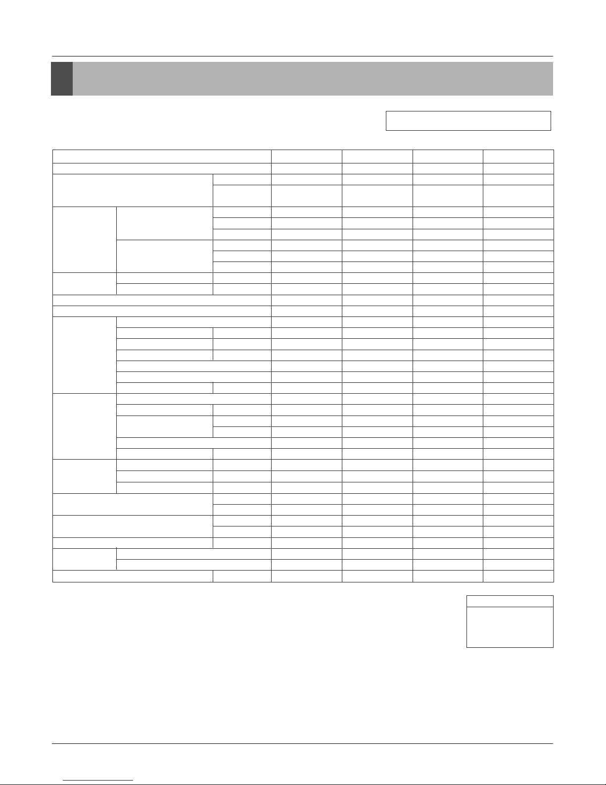
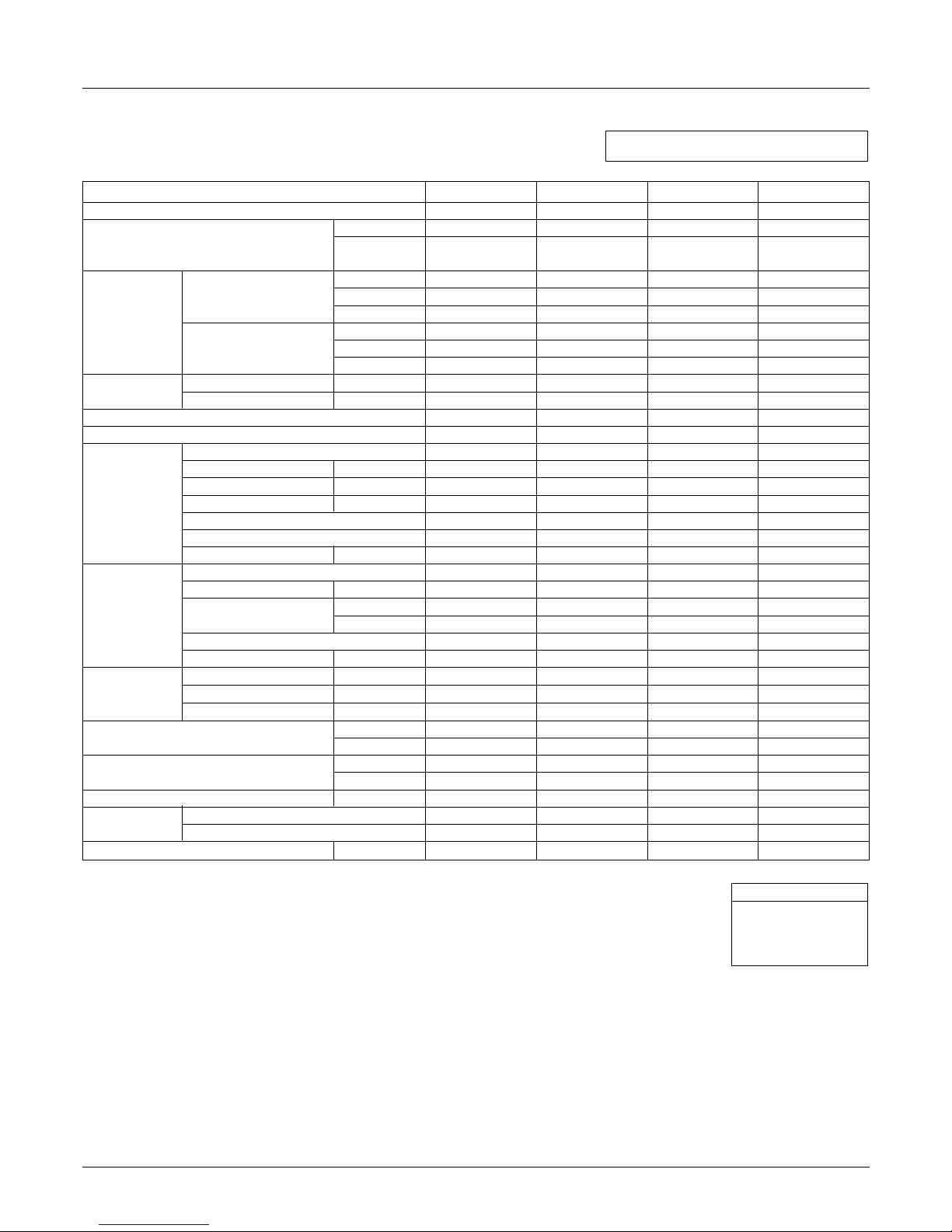
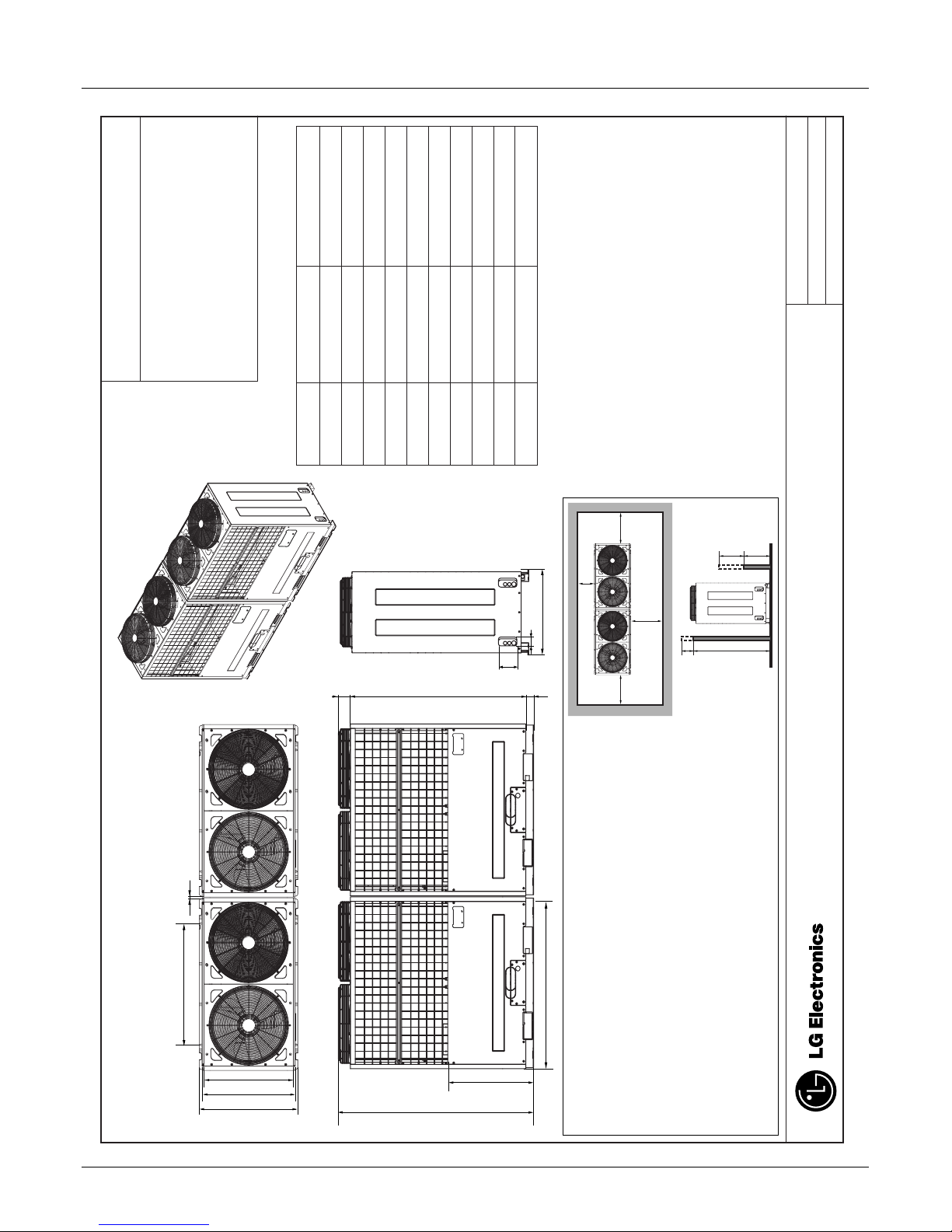
Specification
HP(Equivalent horsepower)
Ton
Model Name Combination Unit
Independent Unit
Capacity Cooling kW
kcal/h
Btu/h
Heating kW
kcal/h
Btu/h
Input Cooling kW
Heating kW
Casing Color
Heat Exchanger
Compressor Type
Piston Displacement cm3/rev
Number of Revolution R.P.M
Motor Output x Number
W
Starting Method
Oil Type
Oil Charge cc
Fan Type
Motor Output x Number W
Air Flow Rate(High) CMM
cfm
Drive
Discharge Side / Top
Pipe Connctions Liquid(flare) mm(inch)
Suction Gas mm(inch)
Discharge Gas mm(inch)
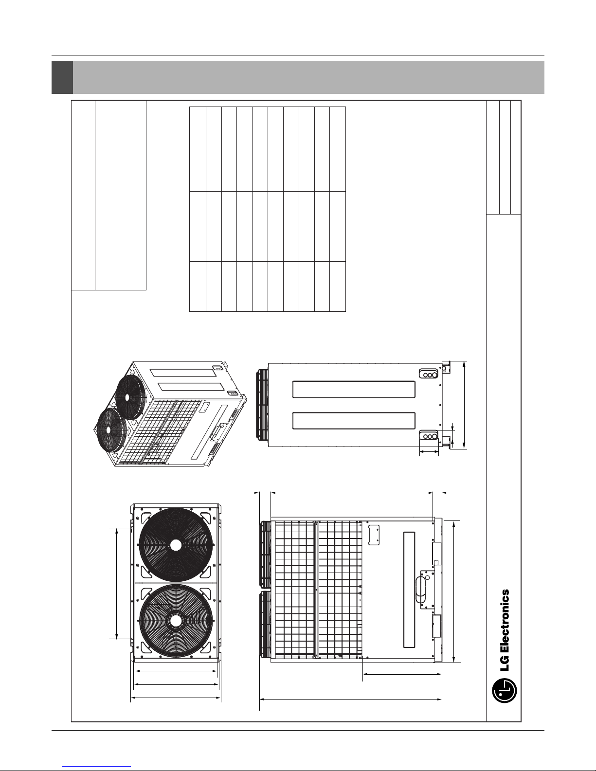
Dimensions (WxHxD) mm
inch
Net Weight kg
lbs
Communication Cable mm2
Refigerant Refigerant name
Control
Power Supply Ø, V, Hz
18 20 22 24
14.5 16.0 17.5 19.0
ARUB173BT2 ARUB192BT2 ARUB211BT2 ARUB230BT2
ARUB096BT2 ARUB096BT2 ARUB115BT2 ARUB115BT2
ARUB076BT2 ARUB096BT2 ARUB096BT2 ARUB115BT2
50.4 56.0 61.6 67.2
43,300 48,200 53,000 57,800
172,000 191,100 210,200 229,300
56.7 63.0 69.3 75.6
48,800 54,200 59,600 65,000
193,500 225,000 236,500 258,000
14.00 15.60 18.60 21.60
15.80 17.60 19.90 22.20
Warm Gray Warm Gray Warm Gray Warm Gray
Gold fin Gold fin Gold fin Gold fin
DC Scroll DC Scroll DC Scroll DC Scroll
(38.3 + 59.8)x2 (38.3 + 59.8)x2 (38.3 + 59.8)x2 (38.3 + 59.8)x2
(3,600+3,500)x2 (3,600+3,500)x2 (3,600+3,500)x2 (3,600+3,500)x2
(4,130 + 5,280)x2 (4,130 + 5,280)x2 (4,130 + 5,280)x2 (4,130 + 5,280)x2
Direct On Line Direct On Line Direct On Line Direct On Line
FVC68D(PVE) FVC68D(PVE) FVC68D(PVE) FVC68D(PVE)
5,600x2 5,600x2 5,600x2 5,600x2
Propeller fan Propeller fan Propeller fan Propeller fan
350 x 4 350 x 4 350 x 4 350 x 4
380 380 380 380
13,400 13,400 13,400 13,400
DC INVERTER DC INVERTER DC INVERTER DC INVERTER
TOP TOP TOP TOP
15.88(5/8) 15.88(5/8) 15.88(5/8) 15.88(5/8)
28.58(1 1/8) 28.58(1 1/8) 34.9(1 3/8) 34.9(1 3/8)
22.2(7/8) 22.2(7/8) 28.58(1 1/8) 28.58(1 1/8)
(1,280x1,607x730)x2 (1,280x1,607x730)x2 (1,280x1,607x730)x2 (1,280x1,607x730)x2
(50-3/8 x 63-5/16 x 28-11/16)x2 (50-3/8 x 63-5/16 x 28-11/16)x2 (50-3/8 x 63-5/16 x 28-11/16)x2 (50-3/8 x 63-5/16 x 28-11/16)x2
285+285 285+285 285+285 285+285
628+628 628+628 628+628 628+628
CVV-SB 1.25x2C CVV-SB 1.25x2C CVV-SB 1.25x2C CVV-SB 1.25x2C
R410A R410A R410A R410A
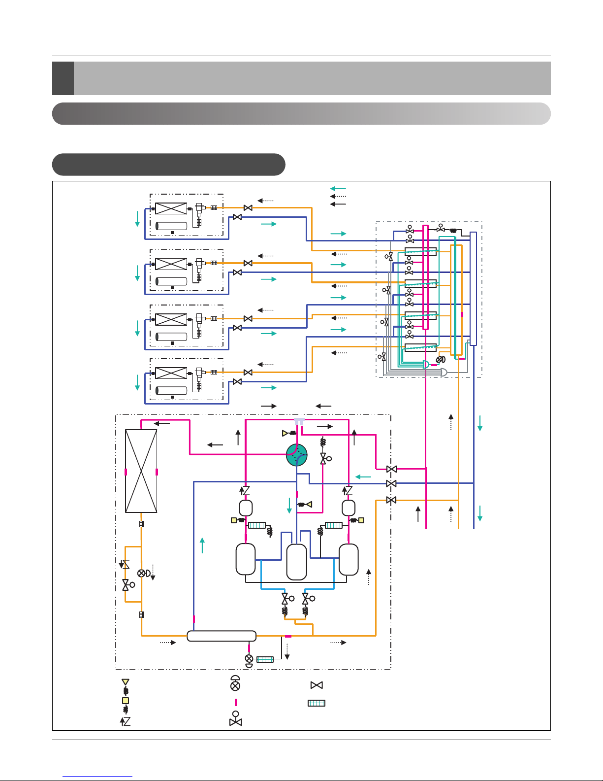
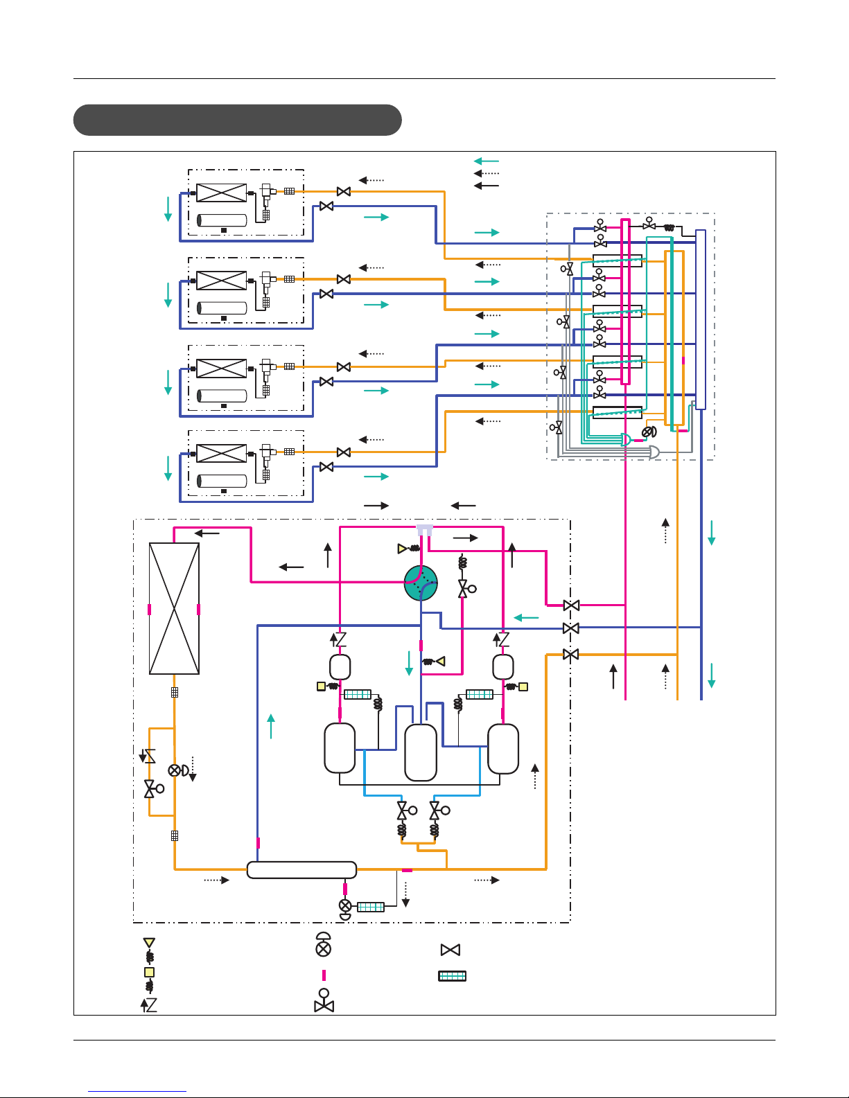
EEV EEV EEV EEV
3, 208/230, 60 3, 208/230, 60 3, 208/230, 60 3, 208/230, 60
Notes:
1. Capacities are based on the following conditions:
Cooling * Indoor temp. 27°C[80.6°F]DB/ 19°C[66.2°F]WB
* Outdoor temp. 35°C[95°F]DB/ 24°C[75.2°F]WB
* Interconnecting Piping Length 7.5m(25ft)
* Level Difference of Zero
Heating * Indoor temp. 20°C[68°F]DB/ 15°C[59°F]WB
* Outdoor temp. 7°C[44.6°F]DB/ 6°C[42.8°F]WB
* Interconnecting Piping Length 7.5m(25ft)
* Level Difference of Zero
2. Capacities are net capacities
3. Due to our policy of innovation some specifications may be changed without prior notification
4. EEV : Electronic Expansion Valve
Heat Recovery(208/230V, 60Hz)
Conversion Formula
kcal/h= kW x 860
Btu/h = kW x 3412
cfm = m3/min x 35.3
l/s = CMM x 1000/60


 null")