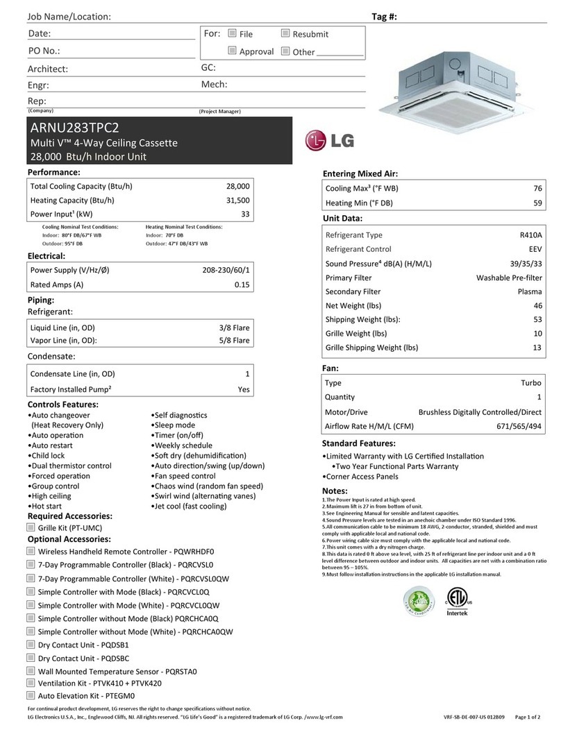
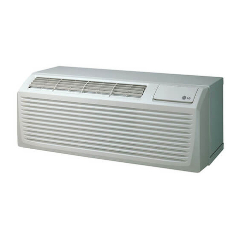
LG LP073IHP.AK3GEUS User manual

www.lg.com
http://www.lghvac.com
Copyright © 2020 LG Electronics Inc. All Rights Reserved.
MFL67646805
Rev.04_111120
OWNER’S MANUAL
AIR CONDITIONER
Read this owner’s manual thoroughly before operating
the appliance and keep it handy for reference at all
times.
ENGLISH FRANÇAIS ESPAÑOL
TYPE: ROOM AIR CONDITIONER

2TABLE OF CONTENTS
TABLE OF CONTENTS
3 SAFETY INSTRUCTIONS
3 IMPORTANT SAFETY INSTRUCTIONS
7 PRODUCT OVERVIEW
9 PREPARING FOR INSTALLATION
9 Contents of Installation Kit
9 Tools and Materials Needed
10 INSTALLATION
10 How to Install the Unit
11 How to connect power supply cord
12 Disassembly Instructions
12 Electrical Data
14 Electrical Safety
15 Subbase (Optional)
17 OPERATION
17 Before Operation
18 Manual Controls
19 Control Panel
20 Additional Controls
25 Self-Diagnosis
27 SMART FUNCTIONS
27 LG ThinQ Application
29 Smart Diagnosis
30 MAINTENANCE
30 Air Filter
31 Vent Filter
32 Unit
32 Compressor and Fan Motor
32 Front Grille
33 TROUBLESHOOTING
33 Before Calling for Service
33 Normal Sounds You May Hear
36 WARRANTY(USA)
37 WARRANTY(CANADA)

SAFETY INSTRUCTIONS 3
ENGLISH
Your safety and the safety of others are very important.
We have provided many important safety instructions in this manual and on your
appliance. Always read and follow all safety instructions.
These words mean:
WARNING
You may be killed or seriously injured if you do not follow instructions.
CAUTION
You may be injured or cause damage to the product if you do not follow instructions.
All safety instructions will tell you what the potential hazard is, tell you how to reduce the
chance of injury, and tell you what may happen if the instructions are not followed.
!
!
This is the safety alert symbol.
This symbol alerts you to potential hazards that can kill or injure you and others.
All safety instructions will follow the safety alert symbol and either the word
WARNING or CAUTION.
!
WARNING
To reduce the risk of explosion, fire, death, electric shock, scalding or
injury to persons when using this product, follow basic precautions,
including the following:
California Proposition 65
• This product contains chemicals known to the State of California to cause cancer
and birth defects or other reproductive harm. Wash hands after handling.
INSTALLATION
• Before use, the appliance must be properly installed as described in this manual.
• Contact the authorized service technician for repair or maintenance of this unit.
• Contact the installer for installation of this unit.
• When the power cord is to be replaced, replacement work shall be performed by
authorized personnel only using only genuine replacement parts.
• Installation work must be performed in accordance with the National Electric Code
by qualified and authorized personnel only.
• Connect to a properly rated, protected, and sized power circuit to avoid electrical
overload.
!
IMPORTANT SAFETY INSTRUCTIONS
SAFETY INSTRUCTIONS
READ ALL INSTRUCTIONS BEFORE USE

4SAFETY INSTRUCTIONS
• Always plug into a grounded outlet.
• Do not under any circumstances, cut or remove the third (ground) prong from the
power cord.
• When installing or moving the appliance, be careful not to pinch, crush, or damage
the power cord.
• Plug in the power plug properly.
• Do not modify or extend the power cord.
• Do not start/stop operation by plugging/unplugging the power cord.
• If the cord/plug is damaged, have it replaced by an authorized service person using
authorized replacement parts.
• Use a dedicated circuit.
• Do not disassemble or modify the product.
• Adhere to all industry recommended safety procedures including the use of long-
sleeved gloves and safety glasses.
• Use care when unpacking and installing. The edges of the product may be sharp.
• Disconnect the power cord or circuit breaker before installing or servicing the
appliance.
• Keep packaging materials out of the reach of children. These materials can pose a
suffocation risk to children.
• Store and install the product where it will not be exposed to temperatures below
freezing or exposed to outdoor weather conditions.
• Do not store or use gasoline or other flammable vapors and liquids in the vicinity of
this or any other appliance.
• Do not install the unit in potentially explosive atmospheres.
OPERATION
• The air conditioner is not intended for use by young children or invalids without
supervision.
• Young children should be supervised to ensure that they do not play with the air
conditioner.
• Use this appliance only for its intended purpose.
• Never attempt to operate this appliance if it is damaged, malfunctioning, partially
disassembled, or has missing or broken parts, including a damaged cord or plug.
• Repair or immediately replace all power cords that have become frayed or
otherwise damaged.
• Do not use a cord that shows cracks or abrasion damage along its length or at
either end.
• Do not run cord under carpets or mats where it could be stepped on and damaged.
• Keep the cord out from under heavy objects like tables or chairs.
• Do not place the power cord near a heat source.
• Do not use an adaptor or plug the product into a shared outlet.
• Do not tamper with controls.
• If you detect a strange sound, a chemical or burning smell, or smoke coming from
the appliance, unplug it immediately, and contact an LG Electronics Customer
Information Center.

SAFETY INSTRUCTIONS 5
ENGLISH
• Never unplug the appliance by pulling on the power cord. Always grip the plug firmly
and pull straight out from the outlet.
• Do not grasp the power cord or touch the appliance controls with wet hands.
• If water enters the product, turn off the power at the main circuit, then unplug the
product and call for service.
• If the product has been submerged, contact an LG Electronics Customer
Information Center for instructions before resuming use.
• Unplug the product when unused for long periods.
• Unplug the product before cleaning.
• In the event of a gas leak (propane gas, etc.) do not operate this or any other
appliance. Open a window or door to ventilate the area immediately.
• This appliance is not intended for use by persons (including children) with reduced
physical, sensory or mental capabilities, or lack of experience and knowledge,
unless they have been given supervision or instruction concerning the use of the
appliance by a person responsible for their safety.
• The interior of the product must only be cleaned by an authorized service center or
a dealer.
• Do not use solvent-based detergent on the product. Doing so can cause corrosion
or damage, product failure, electrical shock, or fire.
GROUNDING INSTRUCTIONS
• The power cord of this appliance is equipped with a three-prong (grounding) plug.
Use this with a standard three-slot (grounding) wall power outlet to minimize the
hazard of electric shock. The customer should have the wall receptacle and circuit
checked by a qualified electrician to make sure the receptacle is properly grounded.
DO NOT CUT OR REMOVE THE THIRD (GROUND) PRONG FROM THE POWER
PLUG.
- Situations when the appliance will be disconnected occasionally; Because of
potential safety hazards, we strongly discourage the use of an adapter plug.
However, if you wish to use an adapter, a TEMPORARY CONNECTION may be
made. Use UL-listed adapter, available from most local hardware stores.
The large slot in the adapter must be aligned with the large slot in the receptacle to
assure a proper polarity connection.
• Attaching the adapter ground terminal to the wall receptacle cover screw does not
ground the appliance unless the cover screw is metal, and not insulated, and the
wall receptacle is grounded through the house wiring. The customer should have
the circuit checked by a qualified electrician to make sure the receptacle is properly
grounded.
• Disconnect the power cord from the adapter, using one hand on each. Otherwise,
the adapter ground terminal might break. Do not use the appliance with a broken
adapter plug.
- Situations when the appliance will be disconnected often; Do not use an adapter
plug in these situations. Unplugging the power cord frequently can lead to an
eventual breakage of the ground terminal. The wall power outlet should be
replaced by a three-slot (grounding) outlet instead.

6SAFETY INSTRUCTIONS
CAUTION
To reduce the risk of minor or moderate injury to persons, malfunction,
or damage to the product or property when using this product, follow
basic precautions, including the following:
INSTALLATION
• Take care when installing the product that exhaust or condensation does not
damage nearby property.
• Follow installation instructions exactly to avoid excessive vibration or water leakage.
• Aluminum building wiring may present special problems—consult a qualified
electrician.
OPERATION
• This appliance is not intended for use as a precision refrigeration system. Do not
use it for special purposes such as maintaining pets, food, precision machinery, or
art objects.
• When installing or moving the appliance, be careful not to pinch, crush, or damage
the power cord.
• Make sure the air inlet and outlet are free from obstructions.
• Use a soft cloth to clean the appliance. Do not use waxes, thinners, or harsh
detergents.
• Do not step on or place heavy objects on top of the appliance.
• Do not operate the appliance without the filter securely installed.
• Do not drink water drained from the appliance.
• Be sure to ventilate sufficiently when the air conditioner and a heating appliance
such as a heater are used simultaneously.
• Being exposed to direct airflow for an extended period of time could be hazardous
to your health.
• Do not expose people, animals, or plants to the cold or hot wind from the air
conditioner for extended periods of time.
MAINTENANCE
• Clean the filter every two weeks.
• Never touch the metal parts of the air conditioner when removing the air filter.
• Never use strong cleaning agents or solvents when cleaning the air conditioner or
spray water.
Use a smooth cloth.
!

PRODUCT OVERVIEW 7
ENGLISH
PRODUCT OVERVIEW
WARNING
• This air conditioner should be installed in accordance with the National Electric Code.
Expanded Metal Grille Should be applied for better performance in PTAC and PTHP Units.
For Installation purpose and better appearance Aluminum Rear Grille or Architecture Rear
Grille can be applied in PTAC and PTHP Units.
!
INDOOR
ALUMINUM REAR GRILLE (Option)
ARCHITECTURE
REAR GRILLE (Option)
EXPANDED METAL GRILLE
(Option)
SLEEVE ASSEMBLY
(Option)
FRONT GRILLE
(Air Intake)
A
IR FILTER
VERTICAL AIR DEFLECTOR
(Horizontal Louver, Air Outlet)

8PRODUCT OVERVIEW
Front Grille
Air Filter
Discharge Grill
Door
Mesh, Metal
Fan
Cover
Brace
Shroud
Fan
Control Box
Compressor
Base pan
Bracket
Pan drain
Evaporator
Vent Door
Rear,Grille
Condenser
Valve, Drain
1
2
3
4
5
6
7
8
9
10
11
12
13
14
15
16
17
18
19
20
1
20
2
510
11
12
13
1415
16
3
4
6 7 8 9
19
18 17

PREPARING FOR INSTALLATION 9
ENGLISH
PREPARING FOR INSTALLATION
Contents of Installation Kit
Tools and Materials Needed
Screws
(6)
Wall thermostat harness
Wire Nuts
(7)
Insulation Strip
Phillips-head
screwdriver
Utility Knife Nipper pliers

10 INSTALLATION
INSTALLATION
How to Install the Unit
1
Measure the wall sleeve and air conditioner di-
mensions.
You can install the new air conditioner according
to these installation instructions to achieve the
best performence. All wall sleeves used to
mount the new air conditioner must be in good
structural condition and have the rear grille(sold
separately) that securely gets attached to the
sleeve or the flange of the sleeve to secure the
new air conditioner.
Dimension of air conditioner
Dimension of sleeve assembly (optional)
2
To avoid vibration and noise, make sure the unit
is installed securely and firmly.
3
When installing the sleeve & Front grille, make
certain there is nothing within 21” back & front of
sleeve & front grille, that would interfere with
heat radiation and exhaust air flow.
4
An insulation strip must be attached.
The insulation strip is provided with the box.
5
After assembly of sleeve & front grille, the gap
should be over 20” from both sleeve & grille.
(See the figure 1.)
Figure 1
6
Take out the insulation strip from the upper
packing.
7
Attach the insulation strip onto the rear upper
side of the wall sleeve.
406 mm
(16")
1,066 mm
(42")
349 mm
(13
3
/
4
")
536 mm
(21")
406 mm
(16")
1066 mm
(42")
349 mm
(13
3
/
4
")
Insulation
Joint Gap
Over 20"
HEAT
RADIATION
WALL
WALL
INSULATION
SLEEVE
INTAKE
AIR
COOLED
AIR
1/4" Bubble
of the level
Over 20"
Front Insulation Strip
Rear
Sleeve
280 mm
(11")
CAUTION
• Require 2 people to lift the air conditioner,
it is HEAVY
• Before installation, Check the insulation on
the inner side of the sleeve. If there is no
insulation, place the insulation.
• Check the bottom corner's joint gap of the
sleeve, If there is, fill the gap with putty.
!

INSTALLATION 11
ENGLISH
How to connect power supply cord
1
Remove the front grille by pulling it out at the
bottom to release it, then lift it up along the unit
top front.
2
Remove cover by removing 2 screws from front.
3
Connect accessory power supply cord, and
attach power cord to base pan with screws.
* You need to attach ground wire to cover with a
ground screw.
ELECTRIC HEATER RATING
(CONFIGURATION BASED ON POWER CORD)
4
Replace cover with screws.
Tighten securely.
5
Slide the unit into the wall sleeve and secure
with 4 screws through the unit flange holes.
6
Reinstall the front grille by hooking the top over
the unit top, then pushing it in at the bottom.
POWER
CORD VOLTAGE HEATER
WATTS
HEATER
CURRENT
MAX.
FUSE SIZE
MIN. CIR-
CUIT AM-
PACITY
AYUH2315 230/208 V
2 000/1 650 W
9.2/8.4 A 15 A 11.9 A
AYUH2320 230/208 V
3 000/2 450 W
13.5/12.3 A 20 A 17.2 A
AYUH2330 230/208 V
5 000/4 000 W
22.1/20.2 A 30 A 28.0 A

12 INSTALLATION
Disassembly Instructions
Front grille
1
To remove the front grille, pull out the bottom of
the front grille and then lift up.
Re-install the component by referring to the
removal procedure.
2
To reinstall the front grille, place the tabs over
the top of the unit and push the bottom of front
grille until the clips snap into place.
Angle of discharge grille louvers
• This Room Air Conditioner (PTAC) discharges air
from the top of the unit through reversible, 2-
position discharge grille louvers. The unit is
shipped from the factory with the discharge grille
louvers at an angle of 40° off vertical. In an
alternate position the louvers will be at an angle of
15° off vertical.
• To adjust the air direction, remove the front
grille. Remove the 4 screws that fasten the
discharge grille to the front grille. Rotate the
discharge grille 180°, then assembly the
discharge grille to the front grille with 4 screws.
Electrical Data
Power cord may include a current interrupter device.
TEST and RESET buttons are provided on the plug
case. The device should be tested on a periodic
basis by first pressing the TEST button and then the
RESET button. If the TEST button does not trip or if
the RESET button will not stay engaged, discontinue
use of the air conditioner and contact a qualified
service technician.
NOTICE
The shape may be different according to its model.
INDOOR
INDOOR
INDOOR
40˚
15˚
Screws
WARNING
• Before the following disassembly, POWER
SWITCH is set to OFF and disconnected
the power cord.
!
208/230V~

INSTALLATION 13
ENGLISH
NOTICE
DO NOT USE AN EXTENSION CORD on 208/230 Volt units.
All wiring should be made in accordance with local electrical codes and regulations.
Aluminum house wiring may pose special problems. Consult a qualified electrician.
CAUTION
• The conductors inside this cord are surrounded by shields, which monitor leakage current.
These shields are not grounded. Periodically examine the cord for any damage. Do not use
this product in the event the shields become exposed.
Avoid shock hazard. This unit cannot be user-serviced. Do not open the tamper resistant
sealed portion. All warranties and performance will be voided. This unit is not intended to be
used as an ON/OFF unit.
!
WARNING
• This appliance should be installed in accordance with the National Electrical Code.
• Use of extension cords could cause serious injury or death.
- Do not use an extension cord with this air conditioner.
- Do not use surge protectors or multi-outlet adapters with this air conditioner.
• Never push the TEST button during operation. Doing so can damage the plug.
- Do not remove, modify, or immerse this plug. If this device trips, the cause should be corrected
before further use.
!
Use Wall Receptacle Power Supply Applied Model
Standard 208/230V, 3-wire grounding
receptacle rated 15A
Use 15 AMP. time delay fuse or 15 AMP.
Circuit breaker.
LP073IHP.AK3GEUS
(Y4NV07ANLK0.AK3GEUS),
LP093IHP.AK3GEUS
(Y4NV09ANLK0.AK3GEUS),
LP123IHP.AK3GEUS
(Y4NV12ANLK0.AK3GEUS),
LP153IHP.AK3GEUS
(Y4NV15ANLK0.AK3GEUS)
Standard 208/230V, 3-wire grounding
receptacle rated 20A
Use 20 AMP. time delay fuse or 20 AMP.
Circuit breaker.
Standard 208/230V, 3-wire grounding re-
ceptacle rated 30A
Use 30 AMP. time delay fuse or 30 AMP.
Circuit breaker.

Electrical Safety
IMPORTANT
(PLEASE READ CAREFULLY)
FOR THE USER'S PERSONAL SAFETY, THIS AP-
PLIANCE MUST BE PROPERLY GROUNDED
The power cord(sold separately) of this appliance is
equipped with a three-prong (grounding) plug. Use
this with a standard three-slot (grounding) wall
power outlet to minimize the hazard of electric
shock. The customer should have the wall recepta-
cle and circuit checked by a qualified electrician to
make sure the receptacle is properly grounded.
DO NOT CUT OR REMOVE THE THIRD
(GROUND) PRONG FROM THE POWER PLUG.
A. SITUATIONS WHEN THE APPLIANCE WILL BE
DISCONNECTED OCCASIONALLY
Because of potential safety hazards, we strongly
discourage the use of an adapter plug. However, if
you wish to use an adapter, a TEMPORARY CON-
NECTION may be made. Use UL-listed adapter,
available from most local hardware stores. The large
slot in the adapter must be aligned with the large
slot in the receptacle to assure a proper polarity con-
nection.
Disconnect the power cord from the adapter, using
one hand on each. Otherwise, the adapter ground
terminal might break. DO NOT USE the appliance
with a broken adapter plug.
B. SITUATIONS WHEN THE APPLIANCE WILL BE
DISCONNECTED OFTEN
Do not use an adapter plug in these situations. Un-
plugging the power cord frequently can lead to an
eventual breakage of the ground terminal. The wall
power outlet should be replaced by a three-slot
(grounding) outlet instead.
USE OF EXTENSION CORDS
Because of potential safety hazards, we strongly
discourage the use of an extension cord. However, if
you wish to use an extension cord, use a CSA certi-
fied/UL-listed 3-wire (grounding) extension cord.
CAUTION
• Attaching the adapter ground terminal to
the wall receptacle cover screw does not
ground the appliance unless the cover
screw is metal, and not insulated, and the
wall receptacle is grounded through the
house wiring. The customer should have
the circuit checked by a qualified
electrician to make sure the receptacle is
properly grounded.
!
14 INSTALLATION

INSTALLATION 15
ENGLISH
Subbase (Optional)
The Subbase provides an enclosure for an electrical receptacle, power switch and a circuit breaker. Electrical
connections to the power supply from the unit are made inside the subbase. In addition, the subbase provides
structural support to the Wall Sleeve and to the weight of the PTAC unit .
The Subbase kit consists of two leveling legs for sleeve support and an accurate unit for leveling during instal-
lation. Also, the subbase is pre-wired and is grounded by means of a grounding screw.
Part No.: AYSB1201B Subbase - 208/230V 20A w/o DS
AYSB1301B Subbase - 208/230V 30A w/o DS
AYSB5101 Subbase Panel
AYSB6101 Subbase - Non Electrical
Notes :
w/o DS --> without disconnect switch
w/ DS --> with disconnect switch
NOTE
When using a subbase, the wall sleeve must be installed at a minimum height of 3 – 1/4 inches (83mm) above
a finished floor and at a minimum distance of 2 – 3/4 inches(70mm) from a finished wall.
Side Extension
Panel (2)
Leveling
Bolt
Electrical
Subbase
Access Cover
Leveling Bolt
Hole to Attach
Subbase to Sleeve (2)
Receptacle
Electrical Junction Box

Attachment screw
subbase to side panel(2)
Attachment screw
subbase to Wall sleeve(2)
Adjustable Side
Extension Panel (2)
Wall Sleeve
Insulation
Electrical Subbase
Leveling Bolt
Access Cover
Leveling bolt
Installation Procedure:
1. Disconnect all power to unit.
2. Mark the hole location on sleeve then drill 1/8in
holes. See Figure 2 for hole dimensions on
sleeve.
3. (Optional) Adjustable side extension panels can
be attached to cover open space left between
subbase and wall.
4. Attach side extension panels to subbase using
one black screw on each side so that panel end
extends dimensions from the subbase.
5. Bring power into the subbase electrical junction
box using one of the knockouts for conduit con-
nections.
6. Take electrical junction box cover off and use field
supplied wire nuts to connect power to receptacle
wires. See Figure 3.
7. Attach subbase to wall sleeve. Subbase has side tabs for mounting the subbase to sleeve. Be sure hole on
the side tab is lined up with the pre drilled hole on side of sleeve. Once holes are aligned, attach subbase
to sleeve with one one screw on each side. See Figure 4.
8. Level subbase flush with floor by adjusting leveling bolts beneath each end of subbase.
9. Remove the access cover from the subbase and plug the power cord into receptacle. Route power cord out
of subbase through cord notch in subbase.
10. Restore power to unit.
SIDE VIEW OF WALL SLEEVE
1 3/16 ”
1/2”
Inside Wall
1/8” Hole
Field Wiring
Line Voltage
NEMA 6-20R
Receptacle
230/208 VAC Field Schematic
NEMA 6-30R
Receptacle
16 INSTALLATION
Figure 2
Figure 3
Figure 4

OPERATION 17
ENGLISH
OPERATION
Before Operation
Preparing for Operation
• Contact an installation specialist for installation.
This is NOT a do-it-yourself project.
• Plug in the power plug properly.
• Use a dedicated circuit.
• Do not use an extension cord. Consult a profes-
sional installer or electrician.
• Do not start/stop operation by plugging/unplugging
the power cord.
• If the cord/plug is damaged, replace it with only an
authorized replacement part.
Usage
• Being exposed to direct airflow for an extended pe-
riod of time could be hazardous to your health. Do
not expose occupants, pets, or plants to direct air-
flow for extended periods of time. In other words,
don't sit in the draft.
• Due to the possibility of oxygen deficiency, venti-
late the room when used together with stoves or
other heating devices.
• Do not use this air conditioner for non-specified
special purposes (e.g. preserving precision de-
vices, food, pets, plants, and art objects). Such
usage could damage the items.
Cleaning and Maintenance
• Do not touch the metal parts of the unit when re-
moving the filter. Injuries can occur when handling
sharp metal edges.
• Do not use water to clean inside the air conditioner.
Exposure to water can destroy the insulation, lead-
ing to possible electric shock.
• When cleaning the unit, first make sure that the
power and breaker are turned off. The fan rotates
at a very high speed during operation. There is a
possibility of injury if the unitʼs power is accidentally
triggered on while cleaning inner parts of the unit.
Service
For repair and maintenance, contact your authorized
service dealer.

18 OPERATION
Manual Controls
VENTILATION
To use ventilation door, remove the screw which fas-
ten the ventilation door.(See Figure 5)
The ventilation lever is located to the upper right side
of the unit.
The ventilation lever must be in the CLOSE position in
order to maintain the best cooling & heating condi-
tions.
When outdoor air is necessary in the room, set the
ventilation lever to the OPEN position.
The Ventilation door is opened and outdoor air is
drawn into the room.
This will reduce the cooling or heating efficiency.
NOTE
This effect will reduce the cooling or heating efficiency.
In order to work correctly, installer or customer will
have to remove glass or panels to better exhaust hot
air.
Figure 5
NOTE
A slight heat odor may come from the unit when first
switching to HEAT after the cooling season is over.
This odor, caused by fine dust particles on the
heater, will disappear quickly. This is harmless.
CAUTION
• When the air conditioner has been running
and is turned off or set to the fan position,
wait at least 3 minutes before resetting to
the cooling & heating operations.
!
CAUTION
• PTAC exhausting discharge air in balcony
that is closed off with glass or panels.
This causes hot air to be pulled back into
the fresh air intake.
!
Ventilation door
VENT
OPEN
VENT
CLOSE
Indoor Outdoor
Greenhouse Effect
Enclosed outdoor area
Glass or
panels
CAUTION
• Failure to follow this caution may result in
equipment damage or improper operation.
• Blocking indoor(curtain or bedclothes etc.)
or outdoor discharge air could cause
premature failure of unit.
• If there has a gap between rear side of
product & outside wall, the air splitter need
to be used on unit.
!
INDOOR
INDOOR
Sleeve
Wall
Outside Wall
Air Splitter
Rear side of product

OPERATION 19
ENGLISH
Control Panel
4 3 2 1
5
6
Power
Press to turn the air conditioner ON or OFF.
Delay ON/OFF Timer
Delay ON - When the air conditioner is off, set
it to automatically turn on from 1 to 24 hours
later, at its previous mode and fan settings.
Delay OFF - When the air conditioner is on, set
it to automatically turn off from 1 to 24 hours
later.
NOTE
• Each press of the Timer button advances the
timer by 1 hour. After the last press the display
returns to the temperature setting.
Fan Speed
Press to set the fan speed to SLo(F1), Low(F2),
Med(F3), High(F4). It cycles through the set-
tings as follows: {High(F4) → Med(F3) →
Low(F2) → SLo(F1) → High(F4)}
Operation Mode
Press the Mode button to cycle between 4
types of air conditioner operation: Heat / Cool /
Fan / Dry
Heat - This mode is ideal on cold days to warm
the room quickly. Use the Temp
buttons to set the desired room temperature
and use the Fan Speed button to set the de-
sired fan circulation speed.
Cool - This mode is ideal on hot days to cool
and dehumidify the room quickly. Use the Temp
buttons to set the desired room
temperature and use the Fan Speed button to
set the desired fan circulation speed.
Fan - In this mode the fan circulates air but the
compressor does not run. Use the Fan Speed
button to set fan speed to High, Medium, Low
or Slow. In this mode, you cannot adjust the set
temperature.
Dry - This mode is ideal for rainy and damp
days to dehumidify the room rather than cooling
it significantly. Moisture is removed from the
room by the combination of compressor opera-
tion and the fan speed fixed at Low.
The compressor and fan turn off once the set
temperature is reached. Fan speed cannot be
adjusted in Dry mode.
Temperature Control
The thermostat monitors room temperature to
maintain the desired temperature.
The thermostat can be set between 54°F -
86°F(12.2°C - 30°C) in cool/heat mode.
Press
∨or ∧
arrows to increase or decrease
temperature setting.
Wi-Fi
Enables connection of the air conditioner to the
home Wi-Fi. You need to purchase additional
accessories to use this mode.
NOTE
• Auto Restart : If the air conditioner turns off due to
a power outage, it will restart automatically after 3
minutes (time delay) once the power is restored,
with the same settings as were set before the unit
turned off.
• Energy Saver : This mode can be set by digital
control. Refer to the 'Digital Controls' section for
the setting method.
1
2
3
4
5
6

20 OPERATION
Additional Controls
Digital Controls
Simultaneously press this , buttons and hold for 3 seconds to enter the setup ready state with
the letter in the display.
The 1st Digit number is changed sequentially from 1 to 6 when the button is pressed to select
desired setting option.
Select the 2nd digit value through the buttons and set the desired setting value for each
option.
Automatically save previous setting value when Option is changed by the button.
Simultaneously press this , buttons and hold for 3 seconds to escape the function. (Display
phase temperature during normal escape)
※Escape automatically when no button is pressed for 3 minutes.
* Not available on all models.
Control Type 1 0 Local/Wifi,LG Exclusive Wired Remote Controller(option) Default setting
1 Remote
Energy Saver 20 Off Default setting
1On
Temperature
Display 30 Fahrenheit Default setting
1 Celsius
Cooling Heating
Temperature
Limit 4
0
54°F(12.2°C)~86°F(30.0°C) 54°F(12.2°C)~86°F(30.0°C)
Default setting
1
56°F(13.3°C)~86°F(30.0°C) 54°F(12.2°C)~84°F(28.9°C)
2
58°F(14.4°C)~86°F(30.0°C) 54°F(12.2°C)~82°F(27.8°C)
3
60°F(15.5°C)~86°F(30.0°C) 54°F(12.2°C)~80°F(26.7°C)
4
62°F(16.6°C)~86°F(30.0°C) 54°F(12.2°C)~78°F(25.5°C)
5
64°F(17.7°C)~86°F(30.0°C) 54°F(12.2°C)~76°F(24.4°C)
6
66°F(18.9°C)~86°F(30.0°C) 54°F(12.2°C)~74°F(23.3°C)
7
68°F(20.0°C)~86°F(30.0°C) 54°F(12.2°C)~72°F(22.2°C)
Unit Type 5
0 Cooling+Electric Heater+Heat Pump Default setting
1 Cooilng+Electric Heater
2 Cooling Only
3 Heat Pump Only
Make Up
Air Mode*
(Option)
60 Off Default setting
1On
This manual suits for next models
7
Table of contents
Other LG Air Conditioner manuals
Popular Air Conditioner manuals by other brands

Scotsman
Scotsman C1448R user manual

Retro Aire
Retro Aire R40C Installation, operation & maintenance manual

Carrier
Carrier Fan Coil 42B Installation, operation and maintenance manual

CLIMAVENETA
CLIMAVENETA a-CHD U-2T 606+2209 OPERATING AND INSTALLATION Manual

Be Cool
Be Cool BCP5AC2101F manual

Vivax
Vivax ACP-12CH35REWI R32 user manual