LG LB-E608HL User manual

SERVICE MANUAL
LG LB-E608HL
MODEL

P/No.: 3828A30014U August, 1999
Printed in Korea

Functions
ƒURoom temperature sensor. (Thermistor)
ƒUMaintains the room temperature in accordance with the Setting Temp.
ƒUIndoor fan is delayed for 5 seconds at the starting.
ƒURestarting is inhibited for approx. 3 minutes.
ƒUHigh, Med, Low
ƒUIntermittent operation of fan at low speed.
ƒUThe setting temperature, indoor fan speed and desired operation mode are automatically set.
ƒUBoth the indoor and outdoor fan stops during defrosting.
ƒUHot start after defrost ends.
ƒUThe indoor fan stops until the evaporator piping temperature will be reached at 28°C.
Indoor Unit
Operation ON/OFF by Remote controller
Sensing the Room Temperature
Room temperature control
Starting Current Control
Time Delay Safety Control
Indoor Fan Speed Control
Soft Dry Operation Mode
Deice (defrost) control (Heating)
Hot-start Control (Heating)
Auto Operation
–3–

–4–
Remote Controller
Operation ON/OFF
Operation Mode Selection
Fan Speed Selection
Room Temperature Display
Temperature Setting
Setting the Time or Timer
(Cooling
model only) (Heating
model only)
(Low) (Med) (High)
Cooling Operation Mode ( )
Heating Operation Mode ( ) Soft Dry Operation Mode ( )
Fan Operation Mode
HIMEDLO
Set
: High:39°C ¡ŒLOW:11°C
: Fan Operates without cooling & heating
Cooling Heating
Down to 18°C
Up to 30°C,Down to 16°C
Up to 30°C,
When the air conditioner is turned off by a power failure, it is restarted
automatically after a power resupply.
✓

Product Specifications (Cooling & Heating)
Air Circulation m3/min
Dimensions
(W¡¿H¡¿D)
Net. Weight
mm
kg
W
A
LB-E6080HL
380-415V
–5–
Service Valve &
Connecting Tube
Model Name
Volt
Item Unit
Cooling Capacity Btu/h(W)
Heating Capacity Btu/h(W)
Moisture Removal §⁄/h
Power Source §j, V, Hz
Indoor
Outdoor
Input Cooling
Heating
Running Current Cooling
Heating
E.E.R. Btu/h-W
Indoor
Outdoor
Indoor
Outdoor
Refrigerant (R-22) g
Remocon Type
Liquid
Gas
Drain Hose
Connecting Wire
Main Power Cable
Time Delay Safety Function
Soft Dry
Fan Speed (Indoor)
Timer
Self-Diagnosis
57,000 (16,700)
60,000 (17,580)
7.5
3ø,380-415V~, 50Hz
53
105
7,500
6,000
13
12
8.2
1,230 x 370 x 680
900 x 1,220 x 370
70
95
4,500
L.C.D
1/2" (12.7)
3/4" (19.05)
O
1.25mm2¤C
3.5mm2¤C
O
O
3 (Hi, Med, Low)
24Hrs
O

Dimensions
MODEL:LB-E6080HL
Indoor Unit
900
1220
370
1230 680
370
–6–
Outdoor Unit

Refrigeration Cycle Diagram
• MODEL: LB-E6080HL
(§Rated performance for refrigerant line length of: 5m)
For installation over rated distance, 70g of refrigerant should be added for each meter.
ex) When installed at a distance of 15m, 525g of refrigerant should be added.
(15-7.5) x 70g = 525g
Pipe size(Diameter: ø) Piping length(m) Elevation(m)
MODEL Gas Liquid Rated Max. Rated Max.
LB-E6080HL 3/4" 1/2" 5 30 5 30 70
INDOOR UNIT OUTDOOR UNIT
HEAT
EXCHANGER HEAT
EXCHANGER
COMPRESSOR
GAS SIDE
LIQUID SIDE
COOLING
HEATING
REVERSING
VALVE
CHECK VALVE
CAPILLARY TUBE
–7–
Additional
refrigerant
(g/m)

Wiring Diagram
MODEL: LB-E6080HL
• Indoor Unit
• Outdoor Unit
–8–
2
E
4
FMi
TRANS
WH
BL
BK
GN/YLGN/YL
RD
OR
CN-TRANS2
PWB ASM
CN-POWER
CN-TRANS1
Hi Med Low
CN-MOTOR
RY-FAN
RY-4WAY
RY-COMP
CN-OUT
1
3
E
DC-12V
SIGNAL
GND
Remo.
CN-REMO
INDOOR ELECTRIC CIRCUIT
INDOOR UNITOUTDOOR UNIT
(RD)
(YL)
(BR)
P/NO : 3854A90021K
4
5
3
1
2
COi
GN/YL
CN-TH
EVA
TH ROOM
TH1
RTM
3fl, 380-415V, 50Hz
POWER SUPPLY
S T N
BK BK BK
WH
WH
RD
OR
BK
63H2
WH
D.P C TH
TNS NO NC
WH
OR
BK 52F1
52C 1
2
3
4
5
6
31
T/B1
T/B2
32
B
A
F1
FMo
49FMo FMo
49FMo
YL BK
OR
BK
T3 T2 T1
RD
WH
CM
1 2
3 4
5 6
7 8
YL BK
OR
BK
BK
WH
BL
BL
WH
Co Co
20SV
WH
F1

–9–
Operation Details
(1) The function of main control
1. Time Delay safety Control
• 3min¡ƒ The compressor is ceased for 3minutes to balance the pressure in the refrigeration cycle.
(Protection of compressor)
• 30sec¡ƒThe 4-way valve is ceased for 30sec. to prevent the refrigerant-gas abnormal noise when the Heating
operation is OFF or switched to the other operation mode while compress is off.
While compressor is running, it takes 3~5 seconds to switch.
2. Soft-Dry Operation
• The indoor fan speed is automatically set to the low, so the shift of the indoor fan speed is impossible because of
already being set to the best speed for Dry Operation by Micom Control.
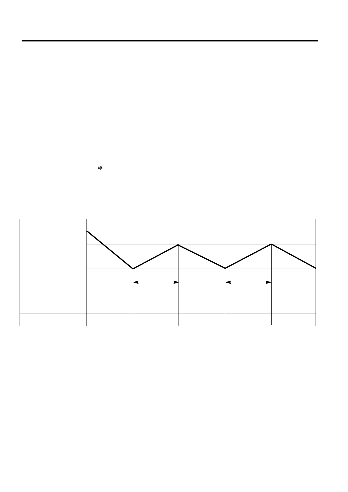
3. Cooling Mode Operation
• When selecting the Cooling( ) Mode Operation, the unit will operate according to the setting by the remote con-
troller and the operation diagram is as following
Intake Air temp.
COMP. ON
(SET TEMP.+0.5°C)
COMP. OFF
(SET TEMP. -0.5°C) More than More than
3 minutes 3 minutes
Selecting Selecting Selecting
fan speed fan speed fan speed
COMPRESSOR ON OFF ON OFF ON
INDOOR FAN Low Low

Intake Air temp.
Setting temp.+3°C
(Compressor OFF)
Setting temp.
(Compressor ON)
INDOOR FAN Low OFF Low Low OFF
COMPRESSOR ON OFF ON OFF
ƒUA point; While the indoor Heat-Exchanger temperature is higher than 35°C fan operates at low speed, when
it becomes lower than 35˚C fan stops.
ƒUB point; When the indoor Heat-Exchanger temperature is higher than 35°C, fan operates at seleted fan
speed, when it becomes lower than 35°C, the fan operates at low speed for 10sec, after 10sec, it
operates at seleted fan speed.
–10–
4. Heating Mode Operation (Except Cooling Model)
The unit will operate according to the setting by the remote controller and the operation diagram is shown as following.
Hot Start
Low
Selecting
Fan Speed
minimum 3min
Selecting fan
speed
minimum
10sec.
1min
A A
minimum
1min. minimum
10sec.
B
5. Hot-Start Control
ƒU The indoor fan stops until the evaporator piping temperature will be reached to 28°C.
ƒUThe operation diagram is as following.
PIPING
TEMPERATURE 1min
COMPRESSOR
INDOOR FAN
ON
26°C
: Selected Fan : Low Fan : Fan Stop
28°C

–11–
6. Defrost Control
• Defrost operation is controlled by timer and sensing the outdoor piping temperature.
• The defrost starts only when the outdoor pipe temperature falls below -6°C after 45 minutes passed from starting
of heating operation.
• Defrost ends after 9 minutes 30 seconds passed from starting of defrost operation or when the outdoor pipe
temperature rises over 12°C even if before 12 minutes.
More than 45 minutes of
heating operation
More than 10 min.
running of compressor
Outdoor Pipe Temp.
Indoor Fan
Compressor
4-Way Valve
ON
ON ON
ON OFF
ON
OFF
HOT-
START
ON
ON OFF OFFON
Within
12minutes
Defrost Defrost
More than 45 minutes of
heating operation
More than 10 min.
running of compressor
7. Self-Diagnosis Function
• 'CHECK' will flash in the remote controller display when a problem occurs. Then please contact your dealer.
• Correct the accident point as shown in the table below before restarting operation.
• During the normal operation 'CHECK' won't be displayed in the remote controller.
Remote controller LCD Accident Point
F1 Indoor temperature thermistor error
F2 Indoor piping thermistor error
F3 Indoor unit & remote controller

–12–
Installation of Indoor, Outdoor Unit
1. Selection of the best location
1) Indoor unit
Select location
Install the air conditioner in the location that satis-
fies the following conditions.
• The place shall easily bear a load exceeding four
times the indoor unit’s weight.
• The place shall be able to inspect the unit as the
figure.
• The place where the unit shall be leveled.
• The place shall allow easy water drainage.(Suit-
able dimension “H” is necessary to get a slope to
drain as figure.)
• The place shall easily connect with the outdoor
unit.
• The place where the unit is not affected by an
electrical noise.
• The place where air circulation in the room will be
good .
• There should not be any heat source or steam
near the unit.
2) Outdoor unit
• If an awning is built over the unit to prevent direct
sunlight or rain exposure, be careful that heat
radiation from the condenser is not restricted.
• There should not be any animals or plants which
could be affected by hot air discharged.
• Ensure the spaces indicated by arrows from the
wall, ceiling, fence or other obstacles.
More than
30cm
More than
30cm
More than
70cm
Fence or
obstacles
Sunroof
H
600600
Top view
(unit: mm)
Front view
Front
Inspection hole
(600X600)
Control box
1000

–13–
Indoor unit
Outdoor unit
B
A
• If 60K Model is installed at a distance of 15m, 525g of
refrigerant should be added (15-7.5) x 70g = 525g
• Capacity is based on standard length and maximun
allowance length is on the basis of reliability.
NOTE:
• Throughly study the following installation locations:
1. In such places as restaurants and kitchens, considerable amount of oil steam and flour adhere to the
fan, the fin of the heat exchanger, resulting in heat exchange reduction, spraying, dispersing of water
drops, etc.
In these cases, take the following actions:
• Make sure that the ventilation fan for smoke-collecting hood on a cooking table has sufficient
capacity so that it draws oily steam which should not flow into the suction of the air conditioner.
• Make enough distance from a cooking room to install the air conditioner in such a place where it
may not suck in oil steam.
2. Avoid installing air conditioner in such circumstances where cutting oil mist or iron powder is in sus-
pension in factories, etc.
3. Avoid places where inflammable gas is generated, flows in, is stored or vented.
4. Avoid places where sulfurous acid gas or corrosive gas is generated.
5. Avoid places near high frequency generators.
3) Piping length and the elevation
MODEL
60K BTU 3/4" 1/2" 5 30
Gas Liquid
530 70
Elevation B(m)
Length A(m) * Additional
refrigerant
(g/m)
Pipe Size
(Diameter: Ø) Standard
Standard
Max. Max.

–14–
A
B
C
1~3mm
Drainage hole
M10 Nut
M10 SP. washer
M10 washer
DE
X 4
X 4 (Local
supply)
X 4
M10 Nut
M10 SP. washer
M10 washer
X 4
X 4 (Local
supply)
X 4
2. Ceiling dimensions and hanging bolt location
■Installation of Unit
Install the unit above the ceiling correctly.
• Apply a joint-canvas between the unit and duct to
absorb unnecessary vibration.
• Apply a filter Accessory at air return hole.
• Install the unit leaning to a drainage hole side as a
figure for easy water drainage.
• A place where the unit will be leveled and that can
support the weight of the unit.
• A place where the unit can withstand its vibration.
• A place where service can be easily performed.
CASE 1
POSITION OF SUSPENSION BOLT
CASE 2
POSITION OF CONSOLE BOLT
(Unit:mm)
Dimension
Capacity
60K
BTU
A B C D E
1292 1230 650.5 54 680

3. The Indoor Unit Installation
• Select and mark the position for fixing bolts.
• Drill the hole for set anchor on the face of ceiling.
• Insert the set anchor and washer onto the sus-
pension bolts for locking the suspension bolts on
the ceiling.
• Mount the suspension bolts to the set anchor
firmly.
• Secure the installation plates onto the suspen-
sion bolts (adjust level roughly) using nuts, wash-
ers and spring washers.
–15–
Tighten the nut and bolt to prevent unit falling
CAUTION
• Local supply
¤Set anchor
¤ŁPlate washer - M10
¤ØSpring washer - M10
¤ŒNut - W3/8 or M10
¤ºSuspension bolt - W3/8 or M10
1 Set anchor
Old building New building
2 Plate washer
3 Spring washer
4 Nut
5 Suspension
bolts

–16–
• Fix the under plate on the wall
• Separate the under plate from Remote control box.
• Fix the cord clamps on the wall by
Ø 3 tapping screws (accessory).
• Fix the remote control cord.
Remote control
box body
Cord clamp
(accessory)
Lever carefully
the box open
using a screw
driver, etc.
Front case
The lower part
Face of wall
Under plate
Screw (accessory)
4. Remote Controller Installation
• Although the room temperature sensor is in the indoor unit, the remote control box should be
installed in such places away from direct sunlight and high humidity.
Installation of the remote control box
• Select places that are not splashed with water.
• Select control position after receiving customer approval.
• The room temperature sensor of the thermostat for temperature control is built in the indoor unit.
• This remote controller equipped with liquid crystal display. If this position is higher or lower, display is difficult
to see.(The standard height is 1.2 ~ 1.5m high)
Routing of the remote control cord
• Keep the remote control cord away from the refrigerant piping and the drain piping.
• To protect the remote control cord from electrical noise, place the cord at least 5cm away from other power
cables (audio equipment, television set, etc.)
• If the remote control cord is secured to a wall, provide a trap at the top of the cord to prevent water droplets
from running.
REMOTE CONTROL BOX INSTALLATION
DISASSEMBLING
ELECTRICAL WIRING
Wire and make sure that teminal
numbers are matched on unit side and
remote controller side.
The maximum length of the cord is 100m.
If the length of the cord exceeds 50m,
use a wire size greater than 0.5mm2.
Remote controller
Yellow,
Red, Brown
(Main board)
CN REMO

1) Connecting cables to the Indoor Unit
■Connect the wires to the terminals on the control board individually according to the outdoor unit connection.
• Ensure that the color of the wires of outdoor unit and the terminal No. are the same as those of indoor unit
respectively
■60K Btu
2) Clamping of cables
1) Arrange 2 power cables on the control panel.
2) First, fasten the steel clamp with a screw to the inner boss of control panel.
3) For the cooling model, fix the other side of the clamp with a screw strongly.
For the heat pump model, put the 0.75mm2cable(thinner cable) on the clamp and tighten it with a plastic
clamp to the other boss of the control panel.
4) In Australia, the length of power supply cord measured from the entry of the power supply cord to the middle
of live pin on the power plug should be over 1.8m.
Terminals on the indoor unit
1 2 4 53
Terminals on the outdoor unit
1 2 4 53
The power cord connected to the outdoor unit should be
complied with the following specifications (Rubber
insulation, type H05RN-F approved by HAR or SAA).
The connecting cable connected to the indoor and outdoor
unit should be complied with the following specifications
(Rubber insulation, type H05RN-F approved by HAR or SAA).
CAUTION
20mm
GN/YL
NORMAL
CROSS-SECTIONAL
AREA 3.5mm
2
(60K)
NORMAL
CROSS-SECTIONAL
AREA 1.25mm
2
(60K)
20mm
GN/YL
–17–
5. Connecting Cables between Indoor Unit and Outdoor Unit
If the supply cord is damaged, it must be replaced by a special cord or assembly availible from the
manufacturer of its service agent.
Make sure that the screws of the terminal are free from looseness.
WARNING

–18–
Outdoor
Indoor
Control terminal board
Control box
Control box cover
(On which the Electric
Wiring Connection is put)
Main terminal board
Control terminal board
Cover control
A A view
Remote
control cord
Connection
cord between
the indoor unit
and the
outdoor unit
Cord clamper
1
1
Main
power source Switch box
Circuit Breaker
Use a 35A(60K)
circuit breaker or time
delay fuse.
ELECTRICAL WIRING
INDOOR UNIT
• Remove the control box cover for electrical con-
nection between the indoor and outdoor
unit.(Remove two screws ➀.)
• Use the cord clamper to fix the cord.
Perform the electrical wiring work according to the electrical wiring
connection.
• All wiring must comply with local requirements.
• Select a power source that is capable of supply-
ing the current required by the air conditioner.
• Use a recognized circuit breaker 35A(60K)
between the power source and the unit. A discon-
nection device to adequately disconnect all supply
lines must be fitted.
WIRING CONNECTION
OUTDOOR UNIT
• Remove the control cover for wiring connection.
• Use the cord clamper to fix the cord.
• Earthing work
Connect the cable of diameter 1.6mm2or more to
the earthing terminal provided in the control box
and do earthing.
¡Please check !!

–19–
6. Connecting Pipes to the Indoor Unit
• Preparation of Piping
Main cause of gas leakage is defect in flaring
work. Carry out correct flaring work in the following
procedure.
1) Cut the pipes and the cable.
■Use the accessory piping kit or the pipes pur-
chased locally.
■Measure the distance between the indoor and
the outdoor unit.
■Cut the pipes a little longer than measured dis-
tance.
■Cut the cable 1.5m longer than the pipe length.
2) Burrs removal
■Completely remove all burrs from the cut cross
section of pipe/tube.
■Put the end of the copper tube/pipe to downward
direction as you remove burrs in order to avoid to
let burrs drop in the tubing.
3) Putting nut on
■Remove flare nuts attached to indoor and out-
door units, than put them on pipe/tube having
completed burr removal.
(Not possible to put them on after flaring work)
4) Flaring work
■Carry out flaring work using flaring tool as shown
below.
Firmly hold copper tube in a bar(or die) as indicat-
ed dimension in the table above.
5) Check
■Compare the flared work with figure.
■If flare is noted to be defective, cut off the flared
section and do flaring work again.
Copper
tube
90°Slanted Uneven Rough
Pipe Reamer
Point down
Flare nut
Copper tube
Bar
Copper pipe
Clamp handle Red arrow mark
Cone
Yoke
Handle
Bar
"A"
Inclined
Inside is shining without scratches.
Smooth all round
Even length
all round
Surface
damaged Cracked Uneven
thickness
= Improper flaring =
Outside Diameter
" A "
Gas Liquid Gas
Liquid
60K BTU 3/4" 1/2" 1.0~1.3 0.5~0.8
Capacity

–20–
1. Form the piping according to its routing. Avoid
bending and bending back the same piping point
more than three times. (This will result in hard-
ening the pipe.)
2. After deforming the piping, align centers of the
union fitting of the indoor unit and the piping, and
tighten them firmly with wrenches.
3. Connect pipe to the service valve or ball valve
which is located below the outdoor unit.
4. After completing the piping connection, be sure
to check if there is gas leakage in indoor and
outdoor connection.
After completing the piping connection, execute
vacuum drying for the connecting piping and the
indoor unit.
The vacuum drying must be carried out using the
service ports of both the liquid and gas side valves.
Use two wrenches and tighten with regular torque.
Outdoor
unit
Liquid side
Flare connection
Flare connection
Gas side
Indoor
unit
Union
Piping Connection
Vacuum drying
CAUTION
Model Liquid side piping Gas side piping
60K BTU 1/2" 3/4"
Pipe size Torque
3/8" 4.2kg.m
1/2" 5.5kg.m
5/8" 6.6kg.m
3/4" 6.6kg.m
Liquid Side
Gas Side
Table of contents
Other LG Air Conditioner manuals