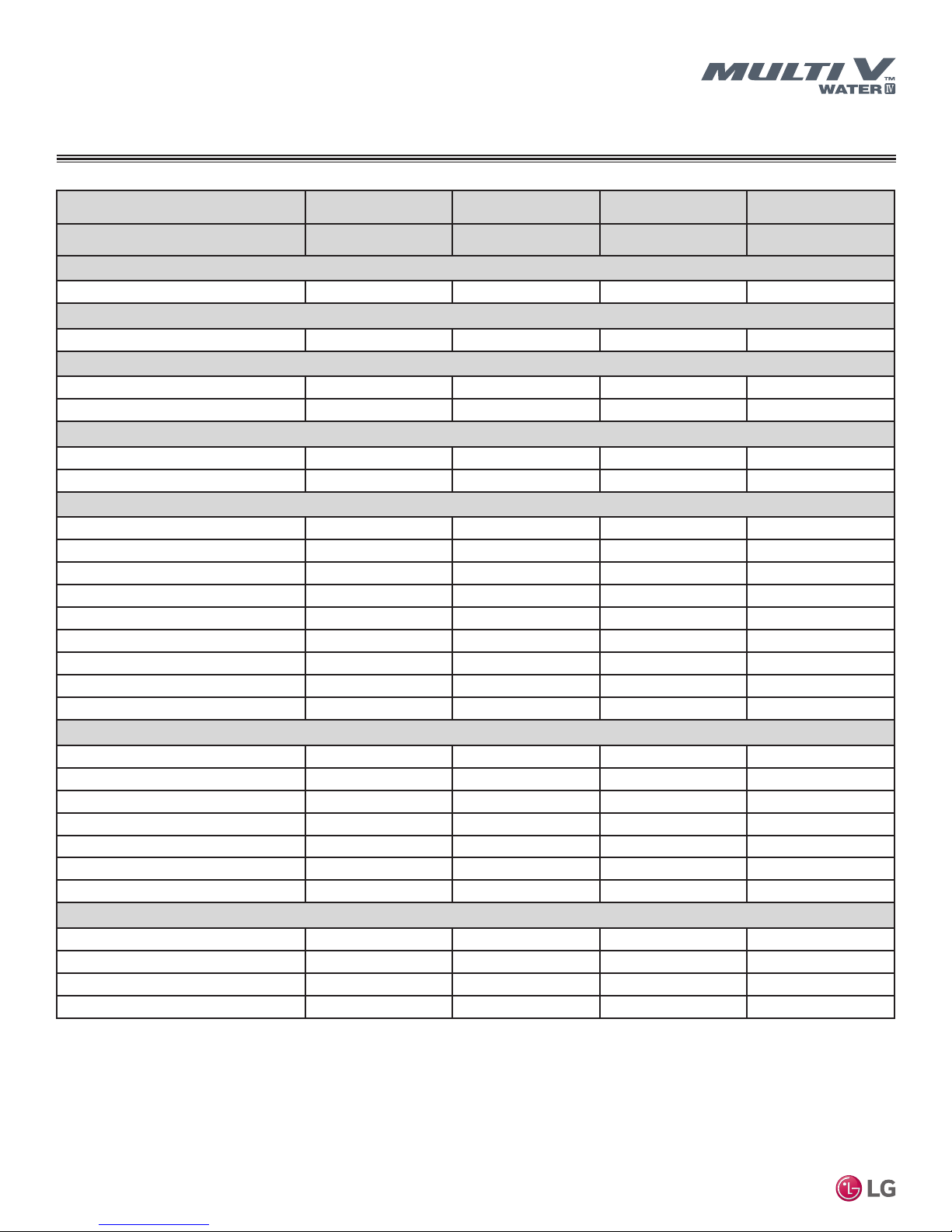
LG Multi V Water IV User manual

INSTALLATION MANUAL
Variable Refrigerant Flow
Water Source Units
6.0 to 48.0 Tons

Follow the instructions in this manual to prevent product malfunction, property damage, injury, or death to users or other people. Incorrect
operation due to ignoring any instructions can cause harm to personnel, or damage to property or equipment.
A summary of safety precautions begins on page 4.
Do not throw away, destroy, or lose this manual.
Please read carefully and store in a safe place for future reference.
Content familiarity required for proper installation and safety of personnel and property.
For more technical materials such as submittals, engineering
databooks, and catalogs, visit www.lghvac.com.
For continual product development, LG Electronics U.S.A., Inc., reserves the right to change specifications without notice.
©LG Electronics U.S.A., Inc.
This document, as well as all reports, illustrations, data, information, and other materials are the property of LG Electronics U.S.A., Inc.
PROPRIETARY DATA NOTICE
This document, as well as all reports, illustrations, data, information, and other
materials herein are the property of LG Electronics U.S.A., Inc., and are
disclosed by LG Electronics U.S.A., Inc., only in confidence.
This document is for design purposes only.
Freight Damage and Unit Replacements......................................................................................Your LG Manufacturer Representative
Missing Parts...............................................................................................................................Your LG Manufacturer Representative
Received Wrong Water Source Unit Model ..................................................................................Your LG Manufacturer Representative
Installation, Startup, and Commissioning Technical Assistance....................................................1-888-865-3026
IM_MultiV_WaterIV_5_16

3
Product Data
Due to our policy of continuous product innovation, some specifications may change without notification.
©LG Electronics U.S.A., Inc., Englewood Cliffs, NJ. All rights reserved. “LG” is a registered trademark of LG Corp.
TABLE OF CONTENTS
Safety Precautions ................................................................................ 4
Unit Nomenclature................................................................................. 8
General Data .......................................................................................... 9
ARWN Series Heat Pump Water Source Unit Specications .............. 9
ARWB Series Heat Recovery Water Source Unit Specications....... 15
Heat Recovery Unit Specications and Electrical Data..................... 21
Electrical Data...................................................................................... 22
ARWN Series Heat Pump Water Source Units ................................. 22
ARWB Series Heat Recovery Water Source Units............................ 23
Water Source Unit Dimensions .......................................................... 24
Single Frame Heat Pump and Heat Recovery .................................. 24
Dual Frame Heat Pump and Heat Recovery..................................... 25
Triple Frame Heat Pump and Heat Recovery.................................... 26
Heat Recovery Units ......................................................................... 27
Refrigerant Flow Diagrams................................................................. 30
ARWN Heat Pump Systems ............................................................ 30;
Cooling Operation........................................................................ 30
Heating Operation ....................................................................... 31
ARWB Heat Recovery Systems ....................................................... 32
Cooling Operation........................................................................ 32
Heating Operation ....................................................................... 33
Simultaneous Operation Mode 1 (Cooling Based Operation)...... 34
Simultaneous Operation Mode 2 (Heating Based Operation) ..... 35
PRHR022A, PRHR032A, PRHR042A Heat Recovery Units ............. 36
Cut Sheets............................................................................................ 37
Water Source Unit Y-branch Kits for Heat Pump Systems ................ 37
Indoor Unit Y-branch Kits for Heat Pump Systems............................ 38
Water Source Unit Y-branch Kits for Heat Recovery Systems........... 39
Indoor Unit Y-branch Kits for Heat Recovery Systems ...................... 40
Header Kits ....................................................................................... 41
Installation............................................................................................ 43
Placement Considerations................................................................. 43
Transporting/Lifting the Water Source Unit....................................... 44
Water Source Unit Minimum Space Requirements ........................... 45
General Mounting / Anchoring the Water Source Unit....................... 47
Heat Recovery Box Minimum Space Requirements ......................... 48
Refrigerant piping Installation............................................................ 49
Computer-assisted Refrigerant Pipe Design ..................................... 49
Pipe Sizing for ARWN Series Heat Pump Systems........................... 59
Pipe Sizing for ARWB Series Heat Recovery Systems ..................... 62
Pipe Layout........................................................................................ 65
Refrigerant Pipe Connections............................................................ 68
Insulating the Refrigerant Piping ....................................................... 70
Pressure (Leak) Testing..................................................................... 73
Water Circuit Installation .................................................................... 75
Water Circuit Design.......................................................................... 75
Field-Supplied Components for WSU Installation ............................. 77
Piping System Specications ............................................................ 78
ELECTRICAL System Installation ...................................................... 85
General Information........................................................................... 85
Power Wiring ..................................................................................... 86
Communication Cable ....................................................................... 87
ARWN Series Heat Pump Systems (208-230V and 460V) ............... 88
ARWB Series Heat Recovery Systems (208-230V and 460V).......... 89
IDU Communication Cable............................................................... 90
Zone Control of Indoor Units ............................................................. 91
Communication Cable ....................................................................... 92
Option Settings for All Water Source Units........................................ 93
Pre-commissioning ............................................................................. 95
Preparing the Electrical System / Indoor Unit Auto Addressing......... 95
Group Control / Central Control......................................................... 99
Indoor Unit Temperature Sensing Strategy/Air Balance.................. 102
Prepare the Refrigerant Piping System........................................... 108
Prepare Pre-comm Documents / Initiate a Request......................... 111
Maintenance........................................................................................112
Maintaining the Heat Exchanger ......................................................112
General Maintenance Schedule .......................................................113
LG Monitoring View (LGMV) Diagnostic Software ..........................115
Error Code Tables...............................................................................117
Installation Checklist......................................................................... 125
Pre-commissioning Checklist .......................................................... 127
Refrigerant Charge Worksheet......................................................... 131
WSU Factory Refrigerant Charge..................................................... 132

4
MULTI V Water IV System Installation Manual
Due to our policy of continuous product innovation, some specifications may change without notification.
©LG Electronics U.S.A., Inc., Englewood Cliffs, NJ. All rights reserved. “LG” is a registered trademark of LG Corp.
SAFETY PRECAUTIONS
The instructions below must be followed to prevent product malfunction, property damage, injury or death to the user or other people. Incor-
rect operation due to ignoring any instructions will cause harm or damage. The level of seriousness is classified by the symbols below.
DANGER
This symbol indicates an imminently hazardous situation which, if not avoided, will result in death
or serious injury.
WARNING
This symbol indicates a potentially hazardous situation which, if not avoided, could result in death
or serious injury.
CAUTION
This symbol indicates a potentially hazardous situation which, if not avoided, may result in minor
or moderate injury.
Note:
This symbol Indicates situations that may result in equipment or property damage accidents only.
This symbol indicates an action that should not be performed.
TABLE OF SYMBOLS
WARNING
The information in this manual is intended for use by
trained, experienced, heating, ventilation, and air condition-
ing (HVAC) technicians who are familiar with variable refrig-
erant ow (VRF) HVAC systems and are equipped with the
proper tools and test equipment. Have an emergency plan.
Know how to obtain emergency medical and reghting as-
sistance.
Failure to carefully read and follow all instructions in this manual can
result in equipment malfunction, property damage, personal injury or
death.
If any system components containing refrigerant are installed
in a small space, take measures to prevent the refrigerant
concentration from exceeding safety limits in the event of a
refrigerant leak.
Consult the latest edition of the American Society of Heating, Refrig-
erating, and Air Conditioning Engineers (ASHRAE) Standard 15. If
the refrigerant leaks and safety limits are exceeded, it could result in
personal injuries or death from oxygen depletion.
Install the unit in a safe location. Avoid areas where it can be
stepped on or fallen into.
There is risk of unit damage, physical injury or death.
Do not install, remove, or re-install the unit by yourself
(end-user). Ask the dealer or a trained technician to install
the unit.
Improper installation by the user may result in water leakage, re,
explosion, electric shock, physical injury or death.
For replacement of an installed unit, always contact an
authorized LG service provider.
There is risk of re, electric shock, explosion, and physical injury or
death.
Do not install the water source units outside.
There is risk of re, electric shock, explosion, and physical injury
or death.
Water source units are shipped with refrigerant and the
service valves closed. Do not open service valves on the
unit until all non-condensibles have been removed from the
piping system and authorization has been obtained from the
commissioning agent.
There is a risk of physical injury or death.
Do not run the compressor with the service valves closed.
There is risk of explosion, physical injury, or death.
Periodically check that the water source unit is not damaged.
There is risk of explosion, physical injury, or death.
Replace all control box and panel covers.
If cover panels are not installed securely, dust, water and animals
may enter the unit, causing re, electric shock, and physical injury or
death.
Always check for system refrigerant leaks after the unit has
been installed or serviced.
Exposure to high concentration levels of refrigerant gas may lead to
illness or death.
Do not install the unit using defective attaching, or mounting
hardware. Do not install the unit on a defective stand.
There is risk of physical injury or death.
Wear protective gloves when handling equipment.
Sharp edges may cause personal injury.
INSTALLATION
DANGER
Don’t use or store ammable gas or combustibles near the unit.
There is risk of re, explosion, and physical injury or death.

5
Product Data
Due to our policy of continuous product innovation, some specifications may change without notification.
©LG Electronics U.S.A., Inc., Englewood Cliffs, NJ. All rights reserved. “LG” is a registered trademark of LG Corp.
SAFETY PRECAUTIONS
INSTALLATION, CONTINUED
WARNING
Dispose the packing materials safely.
• Packing materials, such as nails and other metal or wooden parts
may cause puncture wounds or other injuries.
• Tear apart and throw away plastic packaging bags so that children
may not play with them and risk suffocation and death.
Do not install the unit in any location exposed to open ame
or extreme heat. Do not touch the unit with wet hands.
There is risk of re, electric shock, explosion, and physical injury or death.
Install the unit considering the potential for earthquakes.
Improper installation may cause the unit to fall, resulting in physical
injury or death.
Do not change the settings of the protection devices.
If the pressure switch, thermal switch, or other protection device is
shorted and forced to operate improperly, or parts other than those
specied by LG are used, there is risk of re, electric shock, explo-
sion, and physical injury or death.
If the air conditioner is installed in a small space, take mea-
sures to prevent the refrigerant concentration from exceed-
ing safety limits in the event of a refrigerant leak.
Consult the latest edition of ASHRAE (American Society of Heat-
ing, Refrigerating, and Air Conditioning Engineers) Standard 15. If
the refrigerant leaks and safety limits are exceeded, it could result in
personal injuries or death from oxygen depletion
Note:
LG Electronics U.S.A.,Inc., is not responsible for any piping
calculations, refrigerant leaks, degradation of performance,
or any other potential problems or damages as a result of
interconnecting piping, their joint connections, isolation
valves, introduced debris inside the piping system, or other
problems caused by the interconnecting piping system.
Properly insulate all cold surfaces to prevent “sweating.”
Cold surfaces such as uninsulated pipes can generate condensate
that may drip and cause a slippery oor condition and/or water dam-
age to walls.
When installing the unit in a hospital, mechanical room, or
similar electromagnetic eld (EMF) sensitive environment,
provide sufcient protection against electrical noise.
Inverter equipment, power generators, high-frequency medical equip-
ment, or radio communication equipment may cause the air conditioner
to operate improperly. The unit may also affect such equipment by creat-
ing electrical noise that disturbs medical treatment or image broadcasting.
Do not use the product for special purposes such as preserv-
ing foods, works of art, wine coolers, or other precision air
conditioning applications. This equipment is designed to
provide comfort cooling and heating.
There is risk of property damage.
Do not make refrigerant substitutions. Use R410A only.
If a different refrigerant is used, or air mixes with original refrigerant,
the unit will malfunction and be damaged.
When connecting refrigerant pipe, allow for pipe expansion.
Improper piping may cause refrigerant leaks and system malfunction.
Periodically check that the water source unit is not damaged.
There is a risk of equipment damage.
Take appropriate actions at the end of HVAC equipment life
to recover, recycle, reclaim or destroy R410A refrigerant ac-
cording to applicable U.S. Environmental Protection Agency
(EPA) rules.
Install the water source unit in a safe location where no one
can step on or fall onto it. Do not install the unit with defec-
tive attaching or mounting hardware.
There is risk of unit and property damage.
Install the drain hose to ensure adequate drainage.
There is a risk of water leakage and property damage.
Don’t store or use ammable gas combustibles near the unit.
There is risk of product failure.
Always check for system refrigerant leaks after the unit has
been installed or serviced.
Low refrigerant levels may cause product failure
The unit is shipped with refrigerant and the service valves
closed. Do not open service valves on the unit until all non-
condensibles have been removed from the piping system
and authorization to do so has been obtained from the com-
missioning agent.
There is a risk of refrigerant contamination, refrigerant loss and
equipment damage.
When installing the water source unit in a low-lying area, or
a location that is not level, use a raised concrete pad or con-
crete blocks to provide a solid, level foundation.
A solid, level foundation may prevent water damage and reduce
abnormal vibration.
Do not install the unit in a noise sensitive area.
CAUTION
Be very careful when transporting the product.
• Do not attempt to carry the product without assistance.
• Some products use polypropylene bands for packaging. Do not use
polypropylene bands to lift the unit.
• Suspend the unit from the base at specified positions.
• Support the unit at a minimum of four points to avoid slippage from
rigging apparatus.
• Failure to follow these Cautions can result in minor or moderate
physical injury.

6
MULTI V Water IV System Installation Manual
Due to our policy of continuous product innovation, some specifications may change without notification.
©LG Electronics U.S.A., Inc., Englewood Cliffs, NJ. All rights reserved. “LG” is a registered trademark of LG Corp.
The information in this manual is intended for use by an
industry-qualied, experienced, certied electrician who
is familiar with the U.S. National Electric Code (NEC) and is
equipped with the proper tools and test instruments.
Failure to carefully read and follow all instructions in this manual can
result in equipment malfunction, property damage, personal injury or
death.
All electric work must be performed by a licensed electrician
and conform to local building codes or, in the absence of
local codes, with the National Electrical Code, and the
instructions given in this manual. If there is a conict be-
tween the instructions in this manual and any local or na-
tional codes, follow the requirements of the local or national
codes.
If the power source capacity is inadequate or the electric work is not
performed properly, it may result in re, electric shock, physical injury
or death.
High voltage electricity is required to operate this system.
Adhere to the NEC code and these instructions when wiring.
Improper connections and inadequate grounding can cause acciden-
tal injury or death.
Always ground the unit following local, state, and NEC codes.
There is risk of re, electric shock, and physical injury or death.
Properly size all circuit breakers or fuses.
There is risk of re, electric shock, explosion, physical injury or
death.
Refer to local, state, and federal codes, and use power wires
of sufcient current capacity and rating.
Wires that are too small may generate heat and cause a re.
Secure all eld wiring connections with appropriate wire
strain relief.
Improperly securing wires will create undue stress on equipment
power lugs. Inadequate connections may generate heat, cause a re
and physical injury or death.
Properly tighten all power lugs.
Loose wiring may cause a re by overheating at connection points,
resulting in equipment or property damage, physical injury, or death.
Do not change the settings of the protection devices.
If the pressure switch, thermal switch, or other protection devices are
bypassed or forced to work improperly, or parts other than those
specied by LG are used, there is risk of re, electric shock, explo-
sion, and physical injury or death.
Turn the power off at the nearest disconnect before servicing
the equipment.
Electrical shock can cause physical injury or death.
Do not supply power to the unit until all installation and
precommissioning tasks are complete and the LG authorized
commissioning agent indicates it is safe to do so.
SAFETY PRECAUTIONS
WIRING

7
Product Data
Due to our policy of continuous product innovation, some specifications may change without notification.
©LG Electronics U.S.A., Inc., Englewood Cliffs, NJ. All rights reserved. “LG” is a registered trademark of LG Corp.
SAFETY PRECAUTIONS
Do not allow water, dirt, or animals to enter the unit.
There is risk of unit failure, re, electric shock, physical injury or
death.
Do not provide power to or operate the unit if it is ooded or
submerged.
There is risk of re, electric shock, physical injury or death.
Use a dedicated power disconnect switch for this product.
There is risk of re, electric shock, physical injury or death.
Do not operate the power disconnect switch with wet hands.
There is risk of re, electric shock, physical injury or death.
Periodically verify the equipment mounts have not
deteriorated.
If the base collapses, the unit could fall and cause property damage,
product failure, physical injury or death.
Do not touch the refrigerant piping during or after operation.
It can cause burns or frostbite.
Do not operate the unit with the panel(s) or protective
cover(s) removed; keep ngers and clothing away from
moving parts.
The rotating, hot, cold, and high-voltage parts of the unit can cause
physical injury or death.
If refrigerant gas leaks out, ventilate the area before operat-
ing the unit.
Leaking gas may cause re, electric shock, explosion, physical injury
or death if the water source unit is mounted in an enclosed, low-
lying, or poorly ventilated area and the system develops a refrigerant
leak.
To avoid physical injury, use caution when cleaning or
servicing the air conditioner.
Water source units are shipped with a factory refrigerant
charge and service valves closed. Do not open service valves
on water source units until all non-condensable foreign sub-
stances are removed from the piping system and authorization
to open valves is obtained from the LG-authorized
commissioning agent. Do not run compressors with the
service valves closed.
There is a risk of equipment damage, refrigerant contamination,
refrigerant loss, physical injury or death.
Do not use this equipment in mission critical or special-
purpose applications such as preserving foods, works of art,
wine coolers or refrigeration. The equipment is designed to
provide comfort cooling and heating only.
Oil, steam, sulfuric smoke, etc., can signicantly reduce the performance
of the unit, or damage its parts.
Do not turn off the main power switch after operation has
been stopped.
Wait at least ve (5) minutes before turning off the main power
switch, otherwise it may result in product malfunction.
Provide power to the compressor crankcase heaters at least
six (6) hours before operation begins.
Starting operation with a cold compressor sump(s) may result in se-
vere bearing damage to the compressor(s). Keep the power switch
on during the operational season.
Clean up the site after servicing is nished, and check that
no metal scraps, screws, or bits of wiring have been left
inside or surrounding the unit.
OPERATION
Note
Generation 4 Equipment
The latest versions of LG’s indoor units and water source units are designated Generation 4 (Gen 4). For Gen 4 units to operate with Gen 4
features, the air conditioning system must meet the following requirements:
• All indoor units, heat recovery units, and water source units must be Gen 4.
• All water source units must have Gen 4 software installed.
• Water source units DIP switch 3 must be set to ON (factory default setting is OFF).
• All controllers must support Gen 4 features.

8
MULTI V Water IV System Installation Manual
Due to our policy of continuous product innovation, some specifications may change without notification.
©LG Electronics U.S.A., Inc., Englewood Cliffs, NJ. All rights reserved. “LG” is a registered trademark of LG Corp.
UNIT NOMENCLATURE
Water Source Units
ARW N072 B A S
Generation
4 = Fourth*
Airflow Configuration
A = Not Applicable
Electrical Ratings
B = 208–230V/60Hz/3Phase
D = 460V/60Hz/3Phase
Nominal Capacity
(Nominal cooling capacity in Btu/h)
Type
N = Inverter Heat Pump
B = Inverter Heat Recovery
Family
ARW = Multi V Water IV Water Source Unit (Refrigerant R410A)
4
System Efficiency
S = Standard Efficiency
072 = 72,000
096 = 96,000
121 = 121,000
144 = 144,000
168 = 168,000
192 = 192,000
216 = 216,000
240 = 240,000
288 = 288,000
336 = 336,000
360 = 360,000
384 = 384,000
432 = 432,000
480 = 480,000
576 = 576,000
Heat Recovery Units (HRU)
PRHR 02 2A
Series Number
2A = Series Number
Number of Ports
02 = Two Ports
03 = Three Ports
04 = Four Ports
Family
PRHR = Multi V Heat Recovery (HR) unit (Refrigerant R410A)
*The latest versions of LG’s indoor units and water source units are designated Generation 4 (Gen 4). For Gen 4 units to
operate with Gen 4 features, the air conditioning system must meet the requirements listed on page 7.

9
Product Data
Due to our policy of continuous product innovation, some specifications may change without notification.
©LG Electronics U.S.A., Inc., Englewood Cliffs, NJ. All rights reserved. “LG” is a registered trademark of LG Corp.
Combination Unit Model Number 6.0 Ton
ARWN072BAS4
8.0 Ton
ARWN096BAS4
10.0 Ton
ARWN121BAS4
12.0
ARWN144BAS4
Individual Component Model Numbers
––––
Cooling Performance
Nominal Cooling Capacity (Btu/h)172,000 96,000 120,000 144,000
Heating Performance
Nominal Heating Capacity (Btu/h)181,000 108,000 135,000 162,000
Operating Range (Entering Water Temperature)
Cooling (°F)223 – 113 23 – 113 23 – 113 23 – 113
Heating (°F) 14 – 113 14 – 113 14 – 113 14 – 113
Compressor
Inverter Quantity HSS DC Scroll x 1 HSS DC Scroll x 1 HSS DC Scroll x 1 HSS DC Scroll x 1
Oil/Type PVE/FVC68D PVE/FVC68D PVE/FVC68D PVE/FVC68D
Unit Data
Refrigerant Type R410A R410A R410A R410A
R410A Refrigerant Factory Charge (lbs) 12.8 12.8 12.8 12.8
Refrigerant Control/Location EEV/Indoor Unit EEV/Indoor Unit EEV/Indoor Unit EEV/Indoor Unit
Max. Number Indoor Units/System 13 16 20 23
Sound Pressure dB(A)3 Cooling/Heating 47/51 50/53 56/56 58/57
Net Unit Weight (lbs.) 280 280 280 280
Shipping Weight (lbs.) 302 302 302 302
Communication Cables 2 x 18 AWG 2 x 18 AWG 2 x 18 AWG 2 x 18 AWG
Heat Rejected to Equipment Room (Btu/h) 2,152 2,322 2,493 2,664
Heat Exchanger (Stainless Steel Plate)
Maximum Pressure Resistance (psi) 640 640 640 640
Flow at Rated Condition (GPM) 20.3 25.4 30.4 35.5
Range of Flow (GPM) 8.1 – 30.5 10.2 – 38.1 12.2 – 45.6 14.2 – 53.3
Total Heat of Rejection (Btu/h) 94,400 126,700 157,400 190,100
Total Heat of Absorption (Btu/h) 73,200 96,800 122,000 145,200
Pressure Drop (ft-wg) 3.7 4.7 6.9 9.2
Δt4(°F) 9.3 10.0 10.4 10.7
Piping5
Liquid Line Connection (in., OD) 3/8 Braze 3/8 Braze 1/2 Braze 1/2 Braze
Vapor Line Connection (in., OD) 7/8 Braze 7/8 Braze 1-1/8 Braze 1-1/8 Braze
Water Inlet/Outlet Connection (in) 1-1/2 + 1-1/2 Fem 1-1/2 + 1-1/2 Fem 1-1/2 + 1-1/2 Fem 1-1/2 + 1-1/2 Fem
Condensate Drain (in) 3/4 Female 3/4 Female 3/4 Female 3/4 Female
Table 1: Single-Frame 208-230V Heat Pump Units.
GENERAL DATA
ARWN Series Heat Pump Water Source Unit Specications
1Nominal capacity is outside of AHRI Standard 1230 and based on the following conditions:
• Cooling – Indoor 80°F DB / 66°F WB
Water Temperature Entering: 86°F
• Heating – Indoor 68°F DB
Water Temperature Entering: 68°F
2When entering water temperature is lower than 59ºF, variable water flow control kit PWFCKN000
is required.
3Sound pressure levels are tested in an anechoic chamber under ISO 3745 standard.
4Value is calculated as follows: Δt = Total Heat of Rejection/(Nominal Flow Rate x 500).
5Refer to the Refrigerant Piping section of this manual for correct line sizing. Contractor must use LG
manufactured Y-Branch and Header Kits only. Designer must verify refrigerant piping design configura-
tion using LG’s computerized refrigerant piping software (LATS Multi V) to validate the pipe design.

10
MULTI V Water IV System Installation Manual
Due to our policy of continuous product innovation, some specifications may change without notification.
©LG Electronics U.S.A., Inc., Englewood Cliffs, NJ. All rights reserved. “LG” is a registered trademark of LG Corp.
Table 2: Dual-Frame 208-230V Heat Pump Units.
GENERAL DATA
ARWN Series Heat Pump Water Source Unit Specications
Combination Unit Model Number 14.0 Ton
ARWN168BAS4
16.0 Ton
ARWN192BAS4
18.0 Ton
ARWN216BAS4
24.0 Ton
ARWN288BAS4
Individual Component Model Numbers
ARWN072BAS4 x 1
+ ARWN096BAS4 x 1
ARWN072BAS4 x 1
+ ARWN121BAS4 x 1
ARWN072BAS4 x 1
+ ARWN144BAS4 x 1 ARWN144BAS4 x 2
Cooling Performance
Nominal Cooling Capacity (Btu/h)1168,000 192,000 216,000 288,000
Heating Performance
Nominal Heating Capacity (Btu/h)1189,000 216,000 243,000 324,000
Operating Range (Entering Water Temperature)
Cooling (°F)223 – 113 23 – 113 23 – 113 23 – 113
Heating (°F) 14 – 113 14 – 113 14 – 113 14 – 113
Compressor
Inverter Quantity
HSS DC Scroll x 2 HSS DC Scroll x 2 HSS DC Scroll x 2 HSS DC Scroll x 2
Oil/Type PVE/FVC68D PVE/FVC68D PVE/FVC68D PVE/FVC68D
Unit Data
Refrigerant Type R410A R410A R410A R410A
R410A Refrigerant Factory Charge (lbs) 12.8 + 12.8 12.8 + 12.8 12.8 + 12.8 12.8 + 12.8
Refrigerant Control/Location EEV/Indoor Unit EEV/Indoor Unit EEV/Indoor Unit EEV/Indoor Unit
Max. Number Indoor Units/System 29 32 35 45
Sound Pressure dB(A)3 Cooling/Heating 55/56 54/60 57/57 59/58
Net Unit Weight (lbs.) 280 + 280 280 + 280 280 + 280 280 + 280
Shipping Weight (lbs.) 302 + 302 302 + 302 302 + 302 302 + 302
Communication Cables 2 x 18 AWG 2 x 18 AWG 2 x 18 AWG 2 x 18 AWG
Heat Rejected to Equipment Room (Btu/h) 4,304 4,645 4,816 5,328
Heat Exchanger (Stainless Steel Plate)
Maximum Pressure Resistance (psi) 640 640 640 640
Flow at Rated Condition (GPM) 25.4 + 20.3 30.4 + 20.3 35.5 + 20.3 35.5 + 35.5
Range of Flow (GPM) 18.3 – 68.6 20.3 – 76.1 22.3 – 83.7 28.4 – 106.5
Total Heat of Rejection (Btu/h) 94,400 + 126,700 94,400 + 157,400 94,400 + 190,100 190,100 + 190,100
Total Heat of Absorption (Btu/h) 73,200 + 96,800 73,200 + 122,000 73,200 + 145,200 145,200 + 145,200
Pressure Drop (ft-wg) 3.7 + 4.7 3.7 + 6.9 3.7 + 9.2 9.2 + 9.2
Δt4(°F) 9.7 9.9 10.2 10.7
Piping5
Liquid Line Connection (in., OD) 3/8 + 3/8 Braze 3/8 + 1/2 Braze 3/8 + 1/2 Braze 1/2 + 1/2 Braze
Vapor Line Connection (in., OD) 7/8 + 7/8 Braze 7/8 + 1-1/8 Braze 7/8 + 1-1/8 Braze 1-1/8 + 1-1/8 Braze
Water Inlet/Outlet Connection (in) (1-1/2 + 1-1/2 Fem) x2 (1-1/2 + 1-1/2 Fem) x2 (1-1/2 + 1-1/2 Fem) x2 (1-1/2 + 1-1/2 Fem) x2
Condensate Drain (in) 3/4 Female 3/4 Female 3/4 Female 3/4 Female
1Nominal capacity is outside of AHRI Standard 1230 and based on the following conditions:
• Cooling – Indoor 80°F DB / 66°F WB
Water Temperature Entering: 86°F
• Heating – Indoor 68°F DB
Water Temperature Entering: 68°F
2When entering water temperature is lower than 59ºF, variable water flow control kit PWFCKN000
is required.
3Sound pressure levels are tested in an anechoic chamber under ISO 3745 standard.
4Value is calculated as follows: Δt = Total Heat of Rejection/(Nominal Flow Rate x 500).
5Refer to the Refrigerant Piping section of this manual for correct line sizing. Contractor must use LG
manufactured Y-Branch and Header Kits only. Designer must verify refrigerant piping design configura-
tion using LG’s computerized refrigerant piping software (LATS Multi V) to validate the pipe design.

11
Product Data
Due to our policy of continuous product innovation, some specifications may change without notification.
©LG Electronics U.S.A., Inc., Englewood Cliffs, NJ. All rights reserved. “LG” is a registered trademark of LG Corp.
1Nominal capacity is outside of AHRI Standard 1230 and based on the following conditions:
• Cooling – Indoor 80°F DB / 66°F WB
Water Temperature Entering: 86°F
• Heating – Indoor 68°F DB
Water Temperature Entering: 68°F
2When entering water temperature is lower than 59ºF, variable water flow control kit PWFCKN000
is required.
3Sound pressure levels are tested in an anechoic chamber under ISO 3745 standard.
4Value is calculated as follows: Δt = Total Heat of Rejection/(Nominal Flow Rate x 500).
5Refer to the Refrigerant Piping section of this manual for correct line sizing. Contractor must use LG
manufactured Y-Branch and Header Kits only. Designer must verify refrigerant piping design configura-
tion using LG’s computerized refrigerant piping software (LATS Multi V) to validate the pipe design.
Table 3: Triple-Frame 208-230V Heat Pump Units.
GENERAL DATA
ARWN Series Heat Pump Water Source Unit Specications
Combination Unit Model Number 30.0 Ton
ARWN360BAS4
36.0 Ton
ARWN432BAS4
Individual Component Model Numbers
ARWN072BAS4 x 1 + ARWN144BAS4 x 2 ARWN144BAS4 x 3
Cooling Performance
Nominal Cooling Capacity (Btu/h)1360,000 432,000
Heating Performance
Nominal Heating Capacity (Btu/h)1405,000 486,000
Operating Range (Entering Water Temperature)
Cooling (°F)223 – 113 23 – 113
Heating (°F) 14 – 113 14 – 113
Compressor
Inverter Quantity
HSS DC Scroll x 3 HSS DC Scroll x 3
Oil/Type PVE/FVC68D PVE/FVC68D
Unit Data
Refrigerant Type R410A R410A
R410A Refrigerant Factory Charge (lbs) 12.8 + 12.8 + 12.8 12.8 + 12.8 + 12.8
Refrigerant Control/Location EEV/Indoor Unit EEV/Indoor Unit
Max. Number Indoor Units/System 58 64
Sound Pressure dB(A)3 Cooling/Heating 56/57 58/62
Net Unit Weight (lbs.) 280 + 280 + 280 280 + 280 + 280
Shipping Weight (lbs.) 302 + 302 + 302 302 + 302 + 302
Communication Cables 2 x 18 AWG 2 x 18 AWG
Heat Rejected to Equipment Room (Btu/h) 7,480 7,992
Heat Exchanger (Stainless Steel Plate)
Maximum Pressure Resistance (psi) 640 640
Flow at Rated Condition (GPM) 20.3 + 35.5 + 35.5 35.5 + 35.5 + 35.5
Range of Flow (GPM) 36.5 – 137 42.6 – 159.8
Total Heat of Rejection (Btu/h) 94,400 + 190,100 + 190,100 190,100 + 190,100 + 190,100
Total Heat of Absorption (Btu/h) 73,200 + 145,200 + 145,200 145,200 + 145,200 + 145,200
Pressure Drop (ft-wg) 3.7 + 9.2 + 9.2 9.2 + 9.2 + 9.2
Δt4(°F) 10.4 10.7
Piping5
Liquid Line Connection (in., OD) 3/8 + 1/2+1/2 Braze 1/2+1/2+1/2 Braze
Vapor Line Connection (in., OD) 7/8 + 1-1/8 +1-1/8 Braze 1-1/8 +1-1/8 + 1-1/8 Braze
Water Inlet/Outlet Connection Size (in) (1-1/2 + 1-1/2 Female) x3 (1-1/2 + 1-1/2 Female) x3
Condensate Drain (in) 3/4 Female 3/4 Female

12
MULTI V Water IV System Installation Manual
Due to our policy of continuous product innovation, some specifications may change without notification.
©LG Electronics U.S.A., Inc., Englewood Cliffs, NJ. All rights reserved. “LG” is a registered trademark of LG Corp.
1Nominal capacity is outside of AHRI Standard 1230 and based on the following conditions:
• Cooling – Indoor 80°F DB / 66°F WB
Water Temperature Entering: 86°F
• Heating – Indoor 68°F DB
Water Temperature Entering: 68°F
2When entering water temperature is lower than 59ºF, variable water flow control kit PWFCKN000
is required.
3Sound pressure levels are tested in an anechoic chamber under ISO 3745 standard.
4Value is calculated as follows: Δt = Total Heat of Rejection/(Nominal Flow Rate x 500).
5Refer to the Refrigerant Piping section of this manual for correct line sizing. Contractor must use LG
manufactured Y-Branch and Header Kits only. Designer must verify refrigerant piping design configura-
tion using LG’s computerized refrigerant piping software (LATS Multi V) to validate the pipe design.
Table 4: Single-Frame 460V Heat Pump Units.
GENERAL DATA
ARWN Series Heat Pump Water Source Unit Specications
Combination Unit Model Number 6.0 Ton
ARWN072DAS4
8.0 Ton
ARWN096DAS4
10.0 Ton
ARWN121DAS4
12.0 Ton
ARWN144DAS4
14.0 Ton
ARWN168DAS4
16.0 Ton
ARWN192DAS4
Individual Component Model Numbers
––––––
Cooling Performance
Nominal Cooling Capacity (Btu/h)172,000 96,000 120,000 144,000 168,000 192,000
Heating Performance
Nominal Heating Capacity (Btu/h)181,000 108,000 135,000 162,000 189,000 216,000
Operating Range (Entering Water Temperature)
Cooling (°F)223 – 113 23 – 113 23 – 113 23 – 113 23 – 113 23 – 113
Heating (°F) 14 – 113 14 – 113 14 – 113 14 – 113 14 – 113 14 – 113
Compressor
Inverter Quantity
HSS DC Scroll x 1 HSS DC Scroll x 1 HSS DC Scroll x 1 HSS DC Scroll x 1 HSS DC Scroll x 1 HSS DC Scroll x 1
Oil/Type PVE/FVC68D PVE/FVC68D PVE/FVC68D PVE/FVC68D PVE/FVC68D PVE/FVC68D
Unit Data
Refrigerant Type R410A R410A R410A R410A R410A R410A
R410A Refrigerant Factory Charge (lbs) 12.8 12.8 12.8 6.6 6.6 6.6
Refrigerant Control/Location EEV/Indoor Unit EEV/Indoor Unit EEV/Indoor Unit EEV/Indoor Unit EEV/Indoor Unit EEV/Indoor Unit
Max. Number Indoor Units/System 13 16 20 23 29 32
Sound Pressure dB(A) Cooling/Heating 47/51 50/53 56/56 58/57 53/57 54/60
Net Unit Weight (lbs.) 280 280 280 309 309 309
Shipping Weight (lbs.) 302 302 302 331 331 331
Communication Cables 2 x 18 AWG 2 x 18 AWG 2 x 18 AWG 2 x 18 AWG 2 x 18 AWG 2 x 18 AWG
Heat Rejected to Equipment Room (Btu/h) 2,152 2,322 2,493 2,357 2,459 2,561
Heat Exchanger (Stainless Steel Plate)
Maximum Pressure Resistance (psi) 640 640 640 640 640 640
Flow at Rated Condition (GPM) 20.3 25.4 30.4 35.5 45.7 50.7
Range of Flow (GPM) 8.1 – 30.5 10.2 – 38.1 12.2 – 45.6 14.2 – 53.3 18.3 – 68.6 20.3 – 76.1
Total Heat of Rejection (Btu/h) 94,100 125,900 157.900 190,100 221,100 253,500
Total Heat of Absorption (Btu/h) 74,200 98,600 122,700 146,800 170,100 193,600
Pressure Drop (ft-wg) 3.7 4.7 6.9 4.7 8.0 9.2
Δt4(°F) 9.3 9.9 10.3 10.7 9.7 10.0
Piping5
Liquid Line Connection (in., OD) 3/8 Braze 3/8 Braze 1/2 Braze 1/2 Braze 1/2 Braze 1/2 Braze
Vapor Line Connection (in., OD) 7/8 Braze 7/8 Braze 1-1/8 Braze 1-1/8 Braze 1-1/8 Braze 1-1/8 Braze
Water Inlet/Outlet Connection (in) 1-1/2 + 1-1/2 Fem 1-1/2 + 1-1/2 Fem 1-1/2 + 1-1/2 Fem 1-1/2 + 1-1/2 Fem 1-1/2 + 1-1/2 Fem 1-1/2 + 1-1/2 Fem
Condensate Drain (in) 3/4 Female 3/4 Female 3/4 Female 3/4 Female 3/4 Female 3/4 Female

13
Product Data
Due to our policy of continuous product innovation, some specifications may change without notification.
©LG Electronics U.S.A., Inc., Englewood Cliffs, NJ. All rights reserved. “LG” is a registered trademark of LG Corp.
1Nominal capacity is outside of AHRI Standard 1230 and based on the following conditions:
• Cooling – Indoor 80°F DB / 66°F WB
Water Temperature Entering: 86°F
• Heating – Indoor 68°F DB
Water Temperature Entering: 68°F
2When entering water temperature is lower than 59ºF, variable water flow control kit PWFCKN000
is required.
3Sound pressure levels are tested in an anechoic chamber under ISO 3745 standard.
4Value is calculated as follows: Δt = Total Heat of Rejection/(Nominal Flow Rate x 500).
5Refer to the Refrigerant Piping section of this manual for correct line sizing. Contractor must use LG
manufactured Y-Branch and Header Kits only. Designer must verify refrigerant piping design configura-
tion using LG’s computerized refrigerant piping software (LATS Multi V) to validate the pipe design.
Table 5: Dual-Frame 460V Heat Pump Units.
GENERAL DATA
ARWN Series Heat Pump Water Source Unit Specications
Combination Unit Model Number 20.0 Ton
ARWN240DAS4
24.0 Ton
ARWN288DAS4
28.0 Ton
ARWN336DAS4
32.0 Ton
ARWN384DAS4
Individual Component Model Numbers
ARWN096DAS4
+ ARWN144DAS4
ARWN121DAS4
+ ARWN168DAS4
ARWN168DAS4 x 2
ARWN192DAS4 x 2
Cooling Performance
Nominal Cooling Capacity (Btu/h)1240,000 288,000 336,000 384,000
Heating Performance
Nominal Heating Capacity (Btu/h)1270,000 324,000 378,000 432,000
Operating Range (Entering Water Temperature)
Cooling (°F)223 – 113 23 – 113 23 – 113 23 – 113
Heating (°F) 23 – 113 23 – 113 23 – 113 23 – 113
Compressor
Inverter Quantity HSS DC Scroll x 2 HSS DC Scroll x 2 HSS DC Scroll x 2 HSS DC Scroll x 2
Oil/Type PVE/FVC68D PVE/FVC68D PVE/FVC68D PVE/FVC68D
Unit Data
Refrigerant Type R410A R410A R410A R410A
R410A Refrigerant Factory Charge (lbs) 12.8 + 6.6 12.8 + 6.6 6.6 + 6.6 6.6 + 6.6
Refrigerant Control/Location EEV/Indoor Unit EEV/Indoor Unit EEV/Indoor Unit EEV/Indoor Unit
Max. Number Indoor Units/System 39 45 55 61
Sound Pressure dB(A)3 Cooling/Heating 57/57 59/58 59/61 56/61
Net Unit Weight (lbs.) 280 + 309 280 + 309 309 + 309 309 + 309
Shipping Weight (lbs.) 302 + 331 302 + 331 331 + 331 331 + 331
Communication Cables 2 x 18 AWG 2 x 18 AWG 2 x 18 AWG 2 x 18 AWG
Heat Rejected to Equipment Room (Btu/h) 4,679 4,952 4,918 5122
Heat Exchanger (Stainless Steel Plate)
Maximum Pressure Resistance (psi) 640 640 640 640
Flow at Rated Condition (GPM) 25.4 + 35.5 30.4 + 45.7 45.7 + 45.7 50.7 + 50.7
Range of Flow (GPM) 24.4 – 91.4 30.4 – 114.2 36.6 – 171.4 40.6 – 152.1
Total Heat of Rejection (Btu/h) 125,900 + 190,100 157,900 + 221,100 221,100 x 2 253,500 x 2
Total Heat of Absorption (Btu/h) 98,600 + 146,800 122,700 + 170,100 170,100 x 2 193,600 x 2
Pressure Drop (ft-wg) 4.7 + 4.7 6.9 + 8.0 8.0 + 8.0 9.2 + 9.2
Δt4(°F) 10.4 10.0 9.7 10.0
Piping5
Liquid Line Connection (in., OD) 3/8 + 1/2 Braze 1/2 + 1/2 Braze 1/2 + 1/2 Braze 1/2 + 1/2 Braze
Vapor Line Connection (in., OD) 7/8 + 1-1/8 Braze 7/8 + 1-1/8 Braze 1-1/8 + 1-1/8 Braze 1-1/8 + 1-1/8 Braze
Water Inlet/Outlet Connection Size (in) (1-1/2 + 1-1/2 Fem) x2 (1-1/2 + 1-1/2 Fem) x2 (1-1/2 + 1-1/2 Fem) x2 (1-1/2 + 1-1/2 Fem) x2
Condensate Drain (in) 3/4 Female 3/4 Female 3/4 Female 3/4 Female

14
MULTI V Water IV System Installation Manual
Due to our policy of continuous product innovation, some specifications may change without notification.
©LG Electronics U.S.A., Inc., Englewood Cliffs, NJ. All rights reserved. “LG” is a registered trademark of LG Corp.
1Nominal capacity is outside of AHRI Standard 1230 and based on the following conditions:
• Cooling – Indoor 80°F DB / 66°F WB
Water Temperature Entering: 86°F
• Heating – Indoor 68°F DB
Water Temperature Entering: 68°F
2When entering water temperature is lower than 59ºF, variable water flow control kit PWFCKN000
is required.
3Sound pressure levels are tested in an anechoic chamber under ISO 3745 standard.
4Value is calculated as follows: Δt = Total Heat of Rejection/(Nominal Flow Rate x 500).
5Refer to the Refrigerant Piping section of this manual for correct line sizing. Contractor must use LG
manufactured Y-Branch and Header Kits only. Designer must verify refrigerant piping design configura-
tion using LG’s computerized refrigerant piping software (LATS Multi V) to validate the pipe design.
Table 6: Triple-Frame 460V Heat Pump Units
GENERAL DATA
ARWN Series Heat Pump Water Source Unit Specications
Combination Unit Model Number 40.0 Ton
ARWN480DAS4
48.0 Ton
ARWN576DAS4
Individual Component Model Numbers
ARWN144DAS4 x 2 +
ARWN192DAS4 x 1 ARWN192DAS4 x 3
Cooling Performance
Nominal Cooling Capacity (Btu/h)1480,000 576,000
Heating Performance
Nominal Heating Capacity (Btu/h)1540,000 648,000
Operating Range (Entering Water Temperature)
Cooling (°F)223 – 113 23 – 113
Heating (°F) 14 – 113 14 – 113
Compressor
Inverter Quantity HSS DC Scroll x 3 HSS DC Scroll x 3
Oil/Type PVE/FVC68D PVE/FVC68D
Unit Data
Refrigerant Type R410A R410A
R410A Refrigerant Factory Charge (lbs) 6.6 + 6.6 + 6.6 6.6 + 6.6 + 6.6
Refrigerant Control/Location EEV/Indoor Unit EEV/Indoor Unit
Max. Number Indoor Units/System 64 64
Sound Pressure dB(A)3 Cooling/Heating 60/62 60/62
Net Unit Weight (lbs.) 309 x 3 309 x 3
Shipping Weight (lbs.) 331 x 3 331 x 3
Communication Cables 2 x 18 AWG 2 x 18 AWG
Heat Rejected to Equipment Room (Btu/h) 7,275 7863
Heat Exchanger (Stainless Steel Plate)
Maximum Pressure Resistance (psi) 640 640
Flow at Rated Condition (GPM) 35.5 + 35.5 + 50.7 50.7 + 50.7 + 50.7
Range of Flow (GPM) 48.7 – 182.6 60.8 – 228.2
Total Heat of Rejection (Btu/h) 190,100 + 190,100 + 253,500 253,500 + 253,500 + 253,500
Total Heat of Absorption (Btu/h) 146,800 + 146,800 + 193,600 193,600 + 193,600 + 193,600
Pressure Drop (ft-wg) 4.7 + 4.7 + 9.2 9.2 + 9.2 + 9.2
Δt4(°F) 10.4 10.0
Piping5
Liquid Line Connection (in., OD) 1/2 + 1/2 + 1/2 Braze 1/2 + 1/2 + 1/2 Braze
Vapor Line Connection (in., OD) 1-1/8 + 1-1/8 + 1-1/8 Braze 1-1/8 + 1-1/8 + 1-1/8 Braze
Water Inlet/Outlet Connection Size (in) (1-1/2 + 1-1/2 Fem) x3 (1-1/2 + 1-1/2 Fem) x3
Condensate Drain (in) 3/4 Female 3/4 Female

15
Product Data
Due to our policy of continuous product innovation, some specifications may change without notification.
©LG Electronics U.S.A., Inc., Englewood Cliffs, NJ. All rights reserved. “LG” is a registered trademark of LG Corp.
Table 7: Single-Frame 208-230V Heat Recovery Units.
GENERAL DATA
ARWB Series Heat Recovery Water Source Unit Specications
Combination Unit Model Number 6.0 Ton
ARWB072BAS4
8.0 Ton
ARWB096BAS4
10.0 Ton
ARWB121BAS4
12.0
ARWB144BAS4
Individual Component Model Numbers
––––
Cooling Performance
Nominal Cooling Capacity (Btu/h)172,000 96,000 120,000 144,000
Heating Performance
Nominal Heating Capacity (Btu/h)181,000 108,000 135,000 162,000
Operating Range (Entering Water Temperature)
Cooling (°F)223 – 113 23 – 113 23 – 113 23 – 113
Heating (°F) 23 – 113 23 – 113 23 – 113 23 – 113
Synchronous Operation (°F) 23 – 113 23 – 113 23 – 113 23 – 113
Compressor
Inverter Quantity HSS DC Scroll x1 HSS DC Scroll x1 HSS DC Scroll x1 HSS DC Scroll x1
Oil/Type PVE/FVC68D PVE/FVC68D PVE/FVC68D PVE/FVC68D
Unit Data
Refrigerant Type R410A R410A R410A R410A
R410A Refrigerant Factory Charge (lbs) 12.8 12.8 12.8 12.8
Refrigerant Control/Location EEV/Indoor Unit EEV/Indoor Unit EEV/Indoor Unit EEV/Indoor Unit
Max. Number Indoor Units/System 13 16 20 23
Sound Pressure dB(A)3 Cooling/Heating 47/51 50/53 56/56 58/57
Net Unit Weight (lbs.) 280 280 280 280
Shipping Weight (lbs.) 302 302 302 302
Communication Cables 2 x 18 AWG 2 x 18 AWG 2 x 18 AWG 2 x 18 AWG
Heat Rejected to Equipment Room (Btu/h) 2,152 2,322 2,493 2,664
Heat Exchanger (Stainless Steel Plate)
Maximum Pressure Resistance (psi) 640 640 640 640
Flow at Rated Condition (GPM) 20.3 25.4 30.4 35.5
Range of Flow (GPM) 8.1 – 30.5 10.2 – 38.1 12.2 – 45.6 14.2 – 53.3
Total Heat of Rejection (Btu/h) 94,400 126,700 157,400 190,100
Total Heat of Absorption (Btu/h) 73,200 96,800 122,000 145,200
Pressure Drop (ft-wg) 3.7 4.7 6.9 9.2
Δt4(°F) 9.3 9.9 10.3 10.7
Piping5
Liquid Line Connection (in., OD) 3/8 Braze 3/8 Braze 1/2 Braze 1/2 Braze
Low Press Vapor Line Conn (in., OD) 7/8 Braze 7/8 Braze 1-1/8 Braze 1-1/8 Braze
High Press Vapor Line Conn (in., OD) 3/4 Braze 3/4 Braze 3/4 Braze 3/4 Braze
Water Inlet/Outlet Connection (in) 1-1/2 + 1-1/2 Fem 1-1/2 + 1-1/2 Fem 1-1/2 + 1-1/2 Fem 1-1/2 + 1-1/2 Fem
Condensate Drain (in) 3/4 Female 3/4 Female 3/4 Female 3/4 Female
1Nominal capacity is outside of AHRI Standard 1230 and based on the following conditions:
• Cooling – Indoor 80°F DB / 66°F WB
Water Temperature Entering: 86°F
• Heating – Indoor 68°F DB
Water Temperature Entering: 68°F
2When entering water temperature is lower than 59ºF, variable water flow control kit PWFCKN000
is required.
3Sound pressure levels are tested in an anechoic chamber under ISO 3745 standard.
4Value is calculated as follows: Δt = Total Heat of Rejection/(Nominal Flow Rate x 500).
5Refer to the Refrigerant Piping section of this manual for correct line sizing. Contractor must use LG
manufactured Y-Branch and Header Kits only. Designer must verify refrigerant piping design configura-
tion using LG’s computerized refrigerant piping software (LATS Multi V) to validate the pipe design.

16
MULTI V Water IV System Installation Manual
Due to our policy of continuous product innovation, some specifications may change without notification.
©LG Electronics U.S.A., Inc., Englewood Cliffs, NJ. All rights reserved. “LG” is a registered trademark of LG Corp.
Table 8: Dual-Frame 208-230V Heat Recovery Units.
GENERAL DATA
ARWB Series Heat Recovery Water Source Unit Specications
Combination Unit Model Number 14.0 Ton
ARWB168BAS4
16.0 Ton
ARWB192BAS4
18.0 Ton
ARWB216BAS4
24.0 Ton
ARWB288BAS4
Individual Component Model Numbers
ARWB072BAS4 x 1
+ ARWB096BAS4 x 1
ARWB072BAS4 x 1
+ ARWB121BAS4 x 1
ARWB072BAS4 x 1
+ ARWB144BAS4 x 1 ARWB144BAS4 x 2
Cooling Performance
Nominal Cooling Capacity (Btu/h)1168,000 192,000 216,000 288,000
Heating Performance
Nominal Heating Capacity (Btu/h)1189,000 216,000 243,000 324,000
Operating Range (Entering Water Temperature)
Cooling (°F)223 – 113 23 – 113 23 – 113 23 – 113
Heating (°F) 14 – 113 14 – 113 14 – 113 14 – 113
Synchronous Operation (°F) 23 – 113 23 – 113 23 – 113 23 – 113
Compressor
Inverter Quantity
HSS DC Scroll x 2 HSS DC Scroll x 2 HSS DC Scroll x 2 HSS DC Scroll x 2
Oil/Type PVE/FVC68D PVE/FVC68D PVE/FVC68D PVE/FVC68D
Unit Data
Refrigerant Type R410A R410A R410A R410A
R410A Refrigerant Factory Charge (lbs) 12.8 + 12.8 12.8 + 12.8 12.8 + 12.8 12.8 + 12.8
Refrigerant Control/Location EEV/Indoor Unit EEV/Indoor Unit EEV/Indoor Unit EEV/Indoor Unit
Max. Number Indoor Units/System 29 32 35 45
Sound Press dB(A)3 Cooling/Heating 55/56 54/60 57/57 59/58
Net Unit Weight (lbs.) 280 + 280 280 + 280 280 + 280 280 + 280
Shipping Weight (lbs.) 302 + 302 302 + 302 302 + 302 302 + 302
Communication Cables 2 x 18 AWG 2 x 18 AWG 2 x 18 AWG 2 x 18 AWG
Heat Rejected to Equipment Room (Btu/h) 4,304 4,645 4,816 5,328
Heat Exchanger (Stainless Steel Plate)
Maximum Pressure Resistance (psi) 640 640 640 640
Flow at Rated Condition (GPM) 25.4 + 20.3 30.4 + 20.3 35.5 + 20.3 35.5 + 35.5
Range of Flow (GPM) 18.3 – 68.6 20.3 – 76.1 22.3 – 83.7 28.4 – 106.5
Total Heat of Rejection (Btu/h) 94,400 + 126,700 94,400 + 157,400 94,400 + 190.100 190,100 + 190,100
Total Heat of Absorption (Btu/h) 73,200 + 96,800 73,200 + 122,000 73,200 + 145,200 145,200 + 145,200
Pressure Drop (ft-wg) 3.7 + 4.7 3.7 + 6.9 3.7 + 9.2 9.2 + 9.2
Δt4(°F) 9.6 9.9 10.2 10.7
Piping5
Liquid Line Connection (in., OD) 3/8 + 3/8 Braze 1/2 + 3/8 Braze 1/2 + 3/8 Braze 1/2 + 1/2 Braze
Low Press Vapor Line Conn (in., OD) 7/8 + 7/8 Braze 7/8 + 1-1/8 Braze 7/8 + 1-1/8 Braze 1-1/8 + 1-1/8 Braze
High Press Vapor Line Conn (in., OD) 3/4 + 3/4 Braze 3/4 + 3/4 Braze 3/4 + 3/4 Braze 3/4 + 3/4 Braze
Water Inlet/Outlet Connection (in) (1-1/2 + 1-1/2 Fem) x2 (1-1/2 + 1-1/2 Fem) x2 (1-1/2 + 1-1/2 Fem) x2 (1-1/2 + 1-1/2 Fem) x2
Condensate Drain (in) 3/4 Female 3/4 Female 3/4 Female 3/4 Female
1Nominal capacity is outside of AHRI Standard 1230 and based on the following conditions:
• Cooling – Indoor 80°F DB / 66°F WB
Water Temperature Entering: 86°F
• Heating – Indoor 68°F DB
Water Temperature Entering: 68°F
2When entering water temperature is lower than 59ºF, variable water flow control kit PWFCKN000
is required.
3Sound pressure levels are tested in an anechoic chamber under ISO 3745 standard.
4Value is calculated as follows: Δt = Total Heat of Rejection/(Nominal Flow Rate x 500).
5Refer to the Refrigerant Piping section of this manual for correct line sizing. Contractor must use LG
manufactured Y-Branch and Header Kits only. Designer must verify refrigerant piping design configura-
tion using LG’s computerized refrigerant piping software (LATS Multi V) to validate the pipe design.

17
Product Data
Due to our policy of continuous product innovation, some specifications may change without notification.
©LG Electronics U.S.A., Inc., Englewood Cliffs, NJ. All rights reserved. “LG” is a registered trademark of LG Corp.
Table 9: Triple-Frame 208-230V Heat Recovery Units.
GENERAL DATA
ARWB Series Heat Recovery Water Source Unit Specications
Combination Unit Model Number 30.0 Ton
ARWB360BAS4
36.0 Ton
ARWB432BAS4
Individual Component Model Numbers
ARWB072BAS4 x 1 + ARWB144BAS4 x 2 ARWB144BAS4 x 3
Cooling Performance
Nominal Cooling Capacity (Btu/h)1360,000 432,000
Heating Performance
Nominal Heating Capacity (Btu/h)1405,000 486,000
Operating Range (Entering Water Temperature)
Cooling (°F)223 – 113 23 – 113
Heating (°F) 14 – 113 14 – 113
Synchronous Operation (°F) 23 – 113 23 – 113
Compressor
Inverter Quantity
HSS DC Scroll x 3 HSS DC Scroll x 3
Oil/Type PVE/FVC68D PVE/FVC68D
Unit Data
Refrigerant Type R410A R410A
R410A Refrigerant Factory Charge (lbs) 12.8 + 12.8 + 12.8 12.8 + 12.8 + 12.8
Refrigerant Control/Location EEV/Indoor Unit EEV/Indoor Unit
Max. Number Indoor Units/System258 64
Sound Pressure dB(A)3 Cooling/Heating 56/57 58/62
Net Unit Weight (lbs.) 280 + 280 + 280 280 + 280 + 280
Shipping Weight (lbs.) 302 + 302 + 302 302 + 302 + 302
Communication Cables 2 x 18 AWG 2 x 18 AWG
Heat Rejected to Equipment Room (Btu/h) 7,480 7,992
Heat Exchanger (Stainless Steel Plate)
Maximum Pressure Resistance (psi) 640 640
Flow at Rated Condition (GPM) 35.5 + 35.5 + 20.3 35.5 + 35.5 + 35.5
Range of Flow (GPM) 36.5 – 137.0 42.6 – 159.8
Total Heat of Rejection (Btu/h) 94,400 + 190,100 + 190,100 190,100 + 190,100 + 190,100
Total Heat of Absorption (Btu/h) 73,200 + 145,200 + 145,200 145,200 + 145,200 + 145,200
Pressure Drop (ft-wg) 3.7 + 9.2 + 9.2 9.2 + 9.2 + 9.2
Δt4(°F) 10.4 10.7
Piping5
Liquid Line Connection (in., OD) 3/8 + 1/2 + 1/2 Braze 1/2 + 1/2 + 1/2 Braze
Low Pressure Vapor Line Conn (in., OD) 7/8 + 1-1/8 + 1-1/8 Braze 1-1/8 + 1-1/8 + 1-1/8 Braze
High Pressure Vapor Line Conn (in., OD) 3/4 + 3/4 + 3/4 Braze 3/4 + 3/4 + 3/4 Braze
Water Inlet/Outlet Connection Size (in) (1-1/2 + 1-1/2 Fem) x3 (1-1/2 + 1-1/2 Fem) x3
Condensate Drain (in) 3/4 Female 3/4 Female
1Nominal capacity is outside of AHRI Standard 1230 and based on the following conditions:
• Cooling – Indoor 80°F DB / 66°F WB
Water Temperature Entering: 86°F
• Heating – Indoor 68°F DB
Water Temperature Entering: 68°F
2When entering water temperature is lower than 59ºF, variable water flow control kit PWFCKN000
is required.
3Sound pressure levels are tested in an anechoic chamber under ISO 3745 standard.
4Value is calculated as follows: Δt = Total Heat of Rejection/(Nominal Flow Rate x 500).
5Refer to the Refrigerant Piping section of this manual for correct line sizing. Contractor must use LG
manufactured Y-Branch and Header Kits only. Designer must verify refrigerant piping design configura-
tion using LG’s computerized refrigerant piping software (LATS Multi V) to validate the pipe design.

18
MULTI V Water IV System Installation Manual
Due to our policy of continuous product innovation, some specifications may change without notification.
©LG Electronics U.S.A., Inc., Englewood Cliffs, NJ. All rights reserved. “LG” is a registered trademark of LG Corp.
Table 10: Single-Frame 460V Heat Recovery Units.
GENERAL DATA
ARWB Series Heat Recovery Water Source Unit Specications
Combination Unit Model Number 6.0 Ton
ARWB072DAS4
8.0 Ton
ARWB096DAS4
10.0 Ton
ARWB121DAS4
12.0
ARWB144DAS4 14.0 Ton
ARWB168DAS4 16.0 Ton
ARWB192DAS4
Individual Component Model Numbers – – – – – –
Cooling Performance
Nominal Cooling Capacity (Btu/h)172,000 96,000 120,000 144,000 168,000 192,000
Heating Performance
Nominal Heating Capacity (Btu/h)181,000 108,000 135,000 162,000 189,000 216,000
Operating Range (Entering Water Temperature)
Cooling (°F)223 – 113 23 – 113 23 – 113 23 – 113 23 – 113 23 – 113
Heating (°F) 14 – 113 14 – 113 14 – 113 14 – 113 14 – 113 14 – 113
Synchronous Operation (°F) 23 – 113 23 – 113 23 – 113 23 – 113 23 – 113 23 – 113
Compressor
Inverter Quantity
HSS DC Scroll x 1 HSS DC Scroll x 1 HSS DC Scroll x 1 HSS DC Scroll x 1 HSS DC Scroll x 1 HSS DC Scroll x 1
Oil/Type PVE/FVC68D PVE/FVC68D PVE/FVC68D PVE/FVC68D PVE/FVC68D PVE/FVC68D
Unit Data
Refrigerant Type R410A R410A R410A R410A R410A R410A
R410A Refrigerant Factory Charge (lbs) 12.8 12.8 12.8 6.6 6.6 6.6
Refrigerant Control/Location EEV/Indoor Unit EEV/Indoor Unit EEV/Indoor Unit EEV/Indoor Unit EEV/Indoor Unit EEV/Indoor Unit
Max. Number Indoor Units/System213 16 20 23 29 32
Sound Press dB(A)3 Cooling/Heating 47/51 50/53 56/56 58/57 53/57 54/60
Net Unit Weight (lbs.) 280 280 280 309 309 309
Shipping Weight (lbs.) 302 302 302 331 331 331
Communication Cables 2 x 18 AWG 2 x 18 AWG 2 x 18 AWG 2 x 18 AWG 2 x 18 AWG 2 x 18 AWG
Heat Rejected to Equipment Room (Btu/h)
2,152 2,322 2,493 2,357 2,459 2,561
Heat Exchanger (Stainless Steel Plate)
Maximum Pressure Resistance (psi) 640 640 640 640 640 640
Flow at Rated Condition (GPM) 20.3 25.4 30.4 35.5 45.7 50.7
Range of Flow (GPM) 8.1 – 30.5 10.2 – 38.1 12.2 – 45.6 14.2 – 53.3 18.3 – 68.6 20.3 – 76.1
Total Heat of Rejection (Btu/h) 94,100 125,900 157,900 190,100 221,100 253,500
Total Heat of Absorption (Btu/h) 74,200 98,600 122,700 146,800 170,100 193,600
Pressure Drop (ft-wg) 3.7 4.7 6.9 4.7 8.0 9.2
Δt4(°F) 9.3 9.9 10.3 10.7 9.7 10.0
Piping5
Liquid Line Connection (in., OD) 3/8 Braze 3/8 Braze 1/2 Braze 1/2 Braze 1/2 Braze 1/2 Braze
Low Press Vapor Line Conn (in., OD) 7/8 Braze 7/8 Braze 7/8 Braze 1-1/8 Braze 1-1/8 Braze 1-1/8 Braze
High Press Vapor Line Conn (in., OD) 3/4 Braze 3/4 Braze 3/4 Braze 3/4 Braze 3/4 Braze 3/4 Braze
Water Inlet/Outlet Connection (in) 1-1/2 + 1-1/2 Fem 1-1/2 + 1-1/2 Fem 1-1/2 + 1-1/2 Fem 1-1/2 + 1-1/2 Fem 1-1/2 + 1-1/2 Fem 1-1/2 + 1-1/2 Fem
Condensate Drain (in) 3/4 Female 3/4 Female 3/4 Female 3/4 Female 3/4 Female 3/4 Female
1Nominal capacity is outside of AHRI Standard 1230 and based on the following conditions:
• Cooling – Indoor 80°F DB / 66°F WB
Water Temperature Entering: 86°F
• Heating – Indoor 68°F DB
Water Temperature Entering: 68°F
2When entering water temperature is lower than 59ºF, variable water flow control kit PWFCKN000
is required.
3Sound pressure levels are tested in an anechoic chamber under ISO 3745 standard.
4Value is calculated as follows: Δt = Total Heat of Rejection/(Nominal Flow Rate x 500).
5Refer to the Refrigerant Piping section of this manual for correct line sizing. Contractor must use LG
manufactured Y-Branch and Header Kits only. Designer must verify refrigerant piping design configura-
tion using LG’s computerized refrigerant piping software (LATS Multi V) to validate the pipe design.

19
Product Data
Due to our policy of continuous product innovation, some specifications may change without notification.
©LG Electronics U.S.A., Inc., Englewood Cliffs, NJ. All rights reserved. “LG” is a registered trademark of LG Corp.
Table 11: Dual-Frame 460V Heat Recovery Units.
GENERAL DATA
ARWB Series Heat Recovery Water Source Unit Specications
Combination Unit Model Number 20.0
ARWB240DAS4 24.0
ARWB288DAS4 28.0 Ton
ARWB336DAS4 32.0
ARWB384DAS4
Individual Component Model Numbers ARWB096DAS4 x 1
+ARWB144DAS4 x 1
ARWB121DAS4 x 1
+ARWB168DAS4 x 1 ARWB168DAS4 x 2 ARWB192DAS4 x 2
Cooling Performance
Nominal Cooling Capacity (Btu/h)1240,000 288,000 336,000 384,000
Heating Performance
Nominal Heating Capacity (Btu/h)1270,000 324,000 378,000 432,000
Operating Range (Entering Water Temperature)
Cooling (°F)223 – 113 23 – 113 23 – 113 23 – 113
Heating (°F) 14 – 113 14 – 113 14 – 113 14 – 113
Synchronous Operation (°F) 23 – 113 23 – 113 23 – 113 23 – 113
Compressor
Inverter Quantity HSS DC Scroll x 2 HSS DC Scroll x 2 HSS DC Scroll x 2 HSS DC Scroll x 2
Oil/Type PVE/FVC68D PVE/FVC68D PVE/FVC68D PVE/FVC68D
Unit Data
Refrigerant Type R410A R410A R410A R410A
R410A Refrigerant Factory Charge (lbs) 12.8 + 6.6 12.8 + 6.6 6.6 + 6.6 6.6 + 6.6
Refrigerant Control/Location EEV/Indoor Unit EEV/Indoor Unit EEV/Indoor Unit EEV/Indoor Unit
Max. Number Indoor Units/System239 45 55 61
Sound Pressure dB(A)3 Cooling/Heating 57/57 59/58 59/61 56/61
Net Unit Weight (lbs.) 280 + 309 280 + 309 309 + 309 309 + 309
Shipping Weight (lbs.) 302 + 331 302 + 331 331 + 331 331 + 331
Communication Cables 2 x 18 AWG 2 x 18 AWG 2 x 18 AWG 2 x 18 AWG
Heat Rejected to Equipment Room (Btu/h)
4,679 4952 4918 5122
Heat Exchanger (Stainless Steel Plate)
Maximum Pressure Resistance (psi) 640 640 640 640
Flow at Rated Condition (GPM) 25.4 + 35.5 30.4 + 45.7 45.7 + 45.7 50.7 + 50.7
Range of Flow (GPM) 24.4 – 91.4 30.4 – 114.2 36.6 – 171.4 40.6 – 152.1
Total Heat of Rejection (Btu/h) 125,900 + 190,100 157,900 + 221,100 221,100 x 2 253,500 x 2
Total Heat of Absorption (Btu/h) 98,600 + 146,800 122,700 + 170,100 170,100 x 2 193,600 x 2
Pressure Drop (ft-wg) 4.7 + 4.7 6.9 + 8.0 8.0 + 8.0 9.2 + 9.2
Δt4(°F) 10.4 10.0 9.7 10.0
Piping5
Liquid Line Connection (in., OD) 3/8 + 1/2 Braze 1/2 + 1/2 Braze 1/2 + 1/2 Braze 1/2 + 1/2 Braze
Low Pressure Vapor Line Conn (in., OD) 7/8 + 1-1/8 Braze 7/8 + 1-1/8 Braze 1-1/8 + 1-1/8 Braze 1-1/8 + 1-1/8 Braze
High Pressure Vapor Line Conn (in., OD) 3/4 + 3/4 Braze 3/4 + 3/4 Braze 3/4 + 3/4 Braze 3/4 + 3/4 Braze
Water Inlet/Outlet Connection Size (in) (1-1/2 + 1-1/2 Fem) x2 (1-1/2 + 1-1/2 Fem) x2 (1-1/2 + 1-1/2 Fem) x2 (1-1/2 + 1-1/2 Fem) x2
Condensate Drain (in) 3/4 Female 3/4 Female 3/4 Female 3/4 Female
1Nominal capacity is outside of AHRI Standard 1230 and based on the following conditions:
• Cooling – Indoor 80°F DB / 66°F WB
Water Temperature Entering: 86°F
• Heating – Indoor 68°F DB
Water Temperature Entering: 68°F
2When entering water temperature is lower than 59ºF, variable water flow control kit PWFCKN000
is required.
3Sound pressure levels are tested in an anechoic chamber under ISO 3745 standard.
4Value is calculated as follows: Δt = Total Heat of Rejection/(Nominal Flow Rate x 500).
5Refer to the Refrigerant Piping section of this manual for correct line sizing. Contractor must use LG
manufactured Y-Branch and Header Kits only. Designer must verify refrigerant piping design configura-
tion using LG’s computerized refrigerant piping software (LATS Multi V) to validate the pipe design.

20
MULTI V Water IV System Installation Manual
Due to our policy of continuous product innovation, some specifications may change without notification.
©LG Electronics U.S.A., Inc., Englewood Cliffs, NJ. All rights reserved. “LG” is a registered trademark of LG Corp.
Table 12: Triple-Frame 460V Heat Recovery Units
GENERAL DATA
ARWB Series Heat Recovery Water Source Unit Specications
Combination Unit Model Number 40.0 Ton
ARWB480DAS4 48.0
ARWB576DAS4
Individual Component Model Numbers ARWB144DAS4 x 2
+ARWB192DAS4 x 1 ARWB192DAS4 x 3
Cooling Performance
Nominal Cooling Capacity (Btu/h)1480,000 576,000
Heating Performance
Nominal Heating Capacity (Btu/h)1540,000 648,000
Operating Range (Entering Water Temperature)
Cooling (°F)223 – 113 23 – 113
Heating (°F) 14 – 113 14 – 113
Synchronous Operation (°F) 23 – 113 23 – 113
Compressor
Inverter Quantity HSS DC Scroll x 3 HSS DC Scroll x 3
Oil/Type PVE/FVC68D PVE/FVC68D
Unit Data
Refrigerant Type R410A R410A
R410A Refrigerant Factory Charge (lbs) 6.6 + 6.6 + 6.6 6.6 + 6.6 + 6.6
Refrigerant Control/Location EEV/Indoor Unit EEV/Indoor Unit
Max. Number Indoor Units/System264 64
Sound Pressure dB(A)3 Cooling/Heating 60/62 60/62
Net Unit Weight (lbs.) 309 + 309 + 309 309 + 309 + 309
Shipping Weight (lbs.) 331 + 331 + 331 331 + 331 + 331
Communication Cables 2 x 18 AWG 2 x 18 AWG
Heat Rejected to Equipment Room (Btu/h) 7275 7863
Heat Exchanger (Stainless Steel Plate)
Maximum Pressure Resistance (psi) 640 640
Flow at Rated Condition (GPM) 35.5 + 35.5 + 50.7 50.7 + 50.7 + 50.7
Range of Flow (GPM) 48.7 – 182.6 60.8 – 228.2
Total Heat of Rejection (Btu/h) 190,100 + 190,100 + 253,500 253,500 + 253,500 + 253,500
Total Heat of Absorption (Btu/h) 146,800 + 146,800 + 193,600 193,600 + 193,600 + 193,600
Pressure Drop (ft-wg) 4.7 + 4.7 + 9.2 9.2 + 9.2 + 9.2
Δt4(°F) 10.4 10.0
Piping5
Liquid Line Connection (in., OD) 1/2 + 1/2 + 1/2 Braze 1/2 + 1/2 + 1/2 Braze
Low Pressure Vapor Line Conn (in., OD) 1-1/8 + 1-1/8 + 1-1/8 Braze 1-1/8 + 1-1/8 + 1-1/8 Braze
High Pressure Vapor Line Conn (in., OD) 3/4 + 3/4 + 3/4 Braze 3/4 + 3/4 + 3/4 Braze
Water Inlet/Outlet Connection Size (in) (1-1/2 + 1-1/2 Fem) x3 (1-1/2 + 1-1/2 Fem) x3
Condensate Drain (in) 3/4 Female 3/4 Female
1Nominal capacity is outside of AHRI Standard 1230 and based on the following conditions:
• Cooling – Indoor 80°F DB / 66°F WB
Water Temperature Entering: 86°F
• Heating – Indoor 68°F DB
Water Temperature Entering: 68°F
2When entering water temperature is lower than 59ºF, variable water flow control kit PWFCKN000
is required.
3Sound pressure levels are tested in an anechoic chamber under ISO 3745 standard.
4Value is calculated as follows: Δt = Total Heat of Rejection/(Nominal Flow Rate x 500).
5Refer to the Refrigerant Piping section of this manual for correct line sizing. Contractor must use LG
manufactured Y-Branch and Header Kits only. Designer must verify refrigerant piping design configura-
tion using LG’s computerized refrigerant piping software (LATS Multi V) to validate the pipe design.
Table of contents
Other LG Air Conditioner manuals

LG
LG LAN091CNP, LAU091CNP, LAN121CNP, LAU121CNP, LAN091HNP, LAU091HNP, LAN121HNP, LAU121HNP, LA090CPI, LA090CPO,... User manual

LG
LG LT101CNR User manual

LG
LG LP1215GXR User manual

LG
LG MA12AHV User manual

LG
LG E09SQU User manual

LG
LG B42AWYN7G6 User manual

LG
LG Multi V ARNU07GTRB4 User manual

LG
LG AUUW426D User manual

LG
LG LSN300HLV User manual

LG
LG TB-C096TSG0 User manual