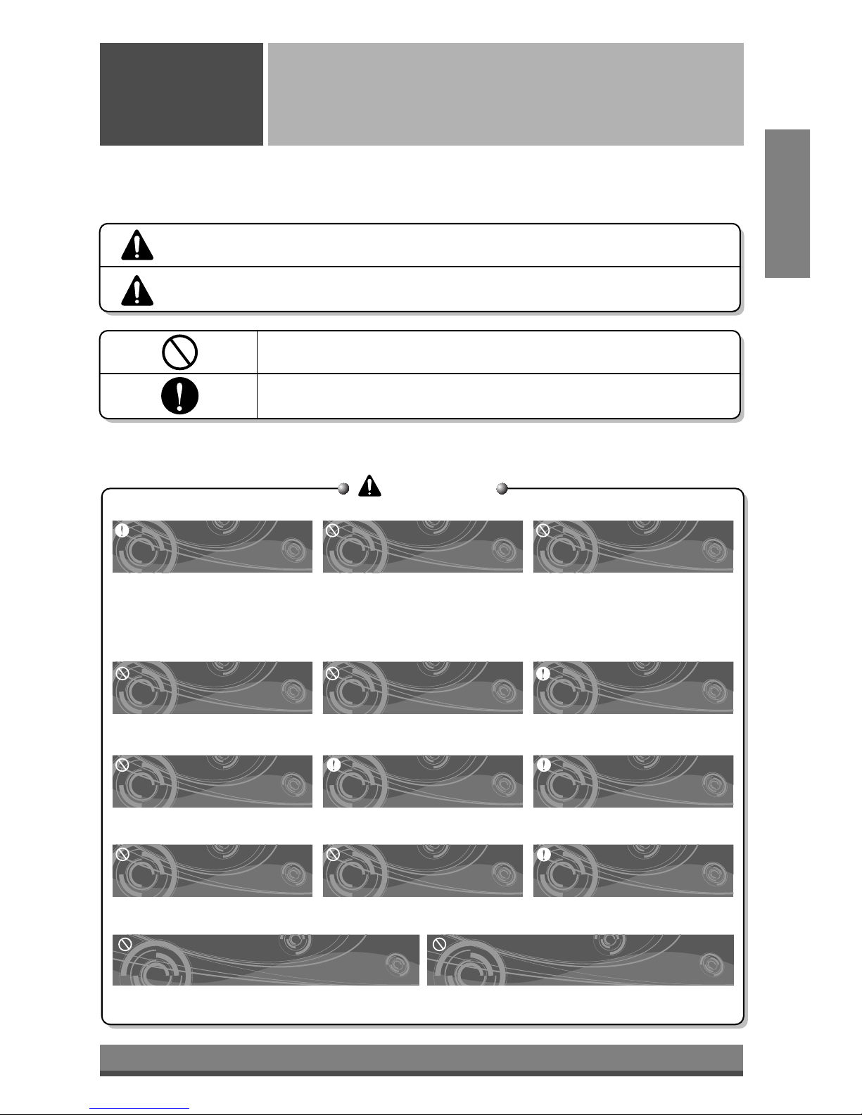
LG LP090HEM User manual

LG
Packaged Terminal Air Conditioner
OWNER'S MANUALOWNER'S MANUAL
LG
Terminal de aire acondicionado embalado
MANUAL DEL PROPIETARIO
MODELS, MODELOS: LP090CEM
LP120CEM
LP090HEM
LP120HEM
LYC073ATA02
LYC123ATA22
LYC123ATA31
LYC123ATA32
LYC123ATB22
LYC153ATA22
LYH073ATA23
LYH073ATA33
LYH073ATC23
LYH093ATA32
LYH093ATA52
LYH153ATA22
LYH153ATA32
LYC07EATA02
LYC09EATA02
LYC09EATA32
LYC12EATA31
LYC12EATA32
LYH07EATA22
LYH07EATA32
LYH09EATA22
IMPORTANT
website http://www.lgappliances.com
• Please read this owner's manual carefully and thoroughly
before installing and operating your room air conditioner.
• Please retain this owner's manual for future reference after
reading it thoroughly.
ESPAÑOLENGLISH

2
FOR YOUR RECORDS
Write the model and serial numbers here:
Model #
Serial #
You can find them on a label on the side of each unit.
Dealer's Name
Date Purchased
■
Staple your receipt to this page in the event you need it
to prove date of purchase or for warranty issues.
READ THIS MANUAL
Inside you will find many helpful hints on how to use and
maintain your air conditioner properly. Just a little
preventive care on your part can save you a great deal
of time and money over the life of your air conditioner.
You'll find many answers to common problems in the
chart of troubleshooting tips. If you review our chart of
Troubleshooting Tips first, you may not need to call for
service at all.
PRECAUTION
•Contact the authorized service technician for repair or
maintenance of this unit.
• Contact the installer for installation of this unit.
• The air conditioner is not intended for use by young
children or invalids without supervision.
• Young children should be supervised to ensure that
they do not play with the air conditioner.
• When the power cord is to be replaced, replacement
work shall be performed by authorized personnel only
using only genuine replacement parts.
• Installation work must be performed in accordance
with the National Electric Code by qualified and
authorized personnel only.
Safety Precautions.................3
Precautions...........................3
Prior to operation ..................5
Introduction ...........................6
Symbols Used in this Manual .....
6
Features ...............................6
Operating Instructions...........7
Control operations ................7
Adjusting the air flow
direction ................................8
Additional controls ................9
Care and Maintenance .........11
Grille and wall sleeve..........11
Outdoor coils ......................11
Air filter ...............................11
Hardware Installation...........12
Product features .................12
Before installing the unit .....12
Prepare the wall sleeve
and outdoor grille................13
Prepare the front grille ........13
Install the unit into the wall
sleeve .................................14
Replace the front grille.......14
How to Install the Unit.........15
Electrical data .....................16
Electrical safety ..................17
Common Issues ...................18
Packaged Terminal Air Conditioner Owner’s Manual
TABLE OF CONTENTS

Never Do This
Always Do This
WARNING
WARNING
CAUTION
Precautions
Safety
Precautions
3
ENGLISH
To prevent injury and property damage, follow these instructions.
Incorrect operation due to ignoring instructions will cause harm or damage, the seriousness of which is
indicated by the following symbols.
■ The following items are classified by these symbols.
Plug in the power plug
properly.
Do not operate or stop the
unit by inserting or pulling
out the power plug.
Do not damage or use an
unspecified power cord.
• Otherwise, it will cause electric
shock or fire due to heat
generation or electric shock.
• It will cause electric shock or fire
due to heat generation. • It will cause electric shock or fire.
•
If the supply cord is damaged, it must be
replaced by the manufacturer or its service
agent or a similarly qualified person in
order to avoid a hazard. (Y attachment)
Do not modify power cord
length or share the outlet
with other appliances.
Do not operate with wet
hands or in damp
environment.
Always plug into a
grounded outlet.
• It will cause electric shock or fire
due to heat generation. • It will cause electric shock.
• No grounding may cause electric
shock (See Installation Manual).
Do not allow water to run
into electric parts.
Always install air leakage
breaker and a dedicated
switching board.
Unplug the unit if strange
sounds, odors, or smoke
comes from it.
• It will cause failure of machine or
electric shock. • No installation may cause fire
and electric shock accident. • It may cause fire and electric
shock accident.
Do not use the socket if it is
loose or damaged.
Do not open the entrance
during operation.
Keep firearms away.
• It may cause fire and electric
shock. • It may cause electric shock. • It may cause fire.
Do not use the power cord close to the
heating tools.
Do not use the power cord near flammable
gas or combustibles such as gasoline,
benzene, thinner, etc.
• It may cause fire and electric shock. • It may cause an explosion or fire.
This symbol shows the possibility of death or serious injury.
This symbol indicates the possibility of injury or damage to property.

WARNING
CAUTION
Do not use strong detergent
such as wax or thinner but
use a soft cloth.
Do not place heavy object on the
power cord and take care so that
the cord should not be pressed.
Do not drink water drained
from air conditioner.
4
Never touch the metal parts
of the unit when removing
the filter.
Do not clean the air
conditioner with water.
Ventilate well when used
together with a stove, etc.
• They are sharp and may cause
injury.
• Water may enter the unit and
degrade the insulation. It may
cause an electric shock.
• An oxygen shortage may occur.
When cleaning the unit, first
make sure the power and
breaker are turned off.
Do not put a pet or house
plant where it will be
exposed to direct air flow.
Do not use appliance for special
purpose such as animals or
vegetables, precision machine, or
conservation of art articles.
• Since the fan rotates at high
speed during operation, it may
cause injury.
• This could injure the pet or plant. • It may cause damage of animals
or vegetables or loss of property.
Stop operation in storm or
hurricanes.
Hold the plug by the head
when taking it out.
Turn off the main power
switch when not using it for
a long time.
• Operation with windows opened
may cause wetting of indoor and
soaking of household furniture.
• It may cause electric shock and
damage.
• It may cause failure of product or
fire.
Do not place obstacles
around the absorption inlet
or output.
Ensure that an installation console of
the outdoor appliance is not damaged
due to the use for a long time.
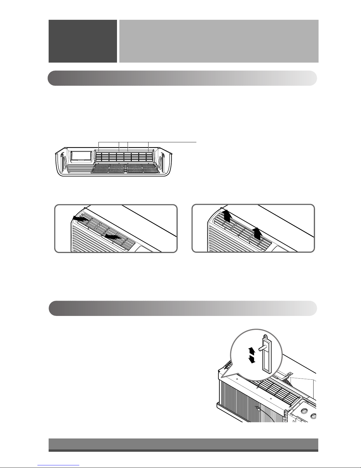
Always insert the filters
securely. Clean it every two
weeks.
• It may cause failure of appliance
or accident.
• If leaving appliance damaged,
there is concern of damage due
to the falling of product.
• Operation without filters will
cause failure.
• Appearance may be deteriorated
due to change of product color or
scratching of its surface.
• There is danger of fire or electric
shock.
• It contains containments and will
make you sick.
Ventilate before operating air conditioner
when gas goes out.
Do not disassemble or modify products
randomly.
• It may cause explosion, fire, and burn. • It may cause failure and electric shock.
If water enters the product, turn
off the the power switch of the
main body of appliance. Contact
service center after taking the
power-plug out from the socket.
Do not direct airflow at
room occupants only.
If you eat the liquid from the
batteries, brush your teeth and
see doctor.Do not use the remote
if the batteries have leaked.
• This could damage your health. •
The chemicals in batteries could
cause burns or other health hazards.

Prior to Operation
Safety
Precautions
5
ENGLISH
Preparing for operation
Contact an installation specialist for installation.
Plug in the power plug properly.
Do not share the same outlet with other appliances
Do not use an extension cord.
Do not start/stop operation by plugging/unplugging the power cord.
If cord/plug is damaged, replace only with an authorized part.
6
5
4
3
2
1
Usage
Being exposed to direct airflow for an extended period of time could be hazardous to your health. Do not
expose occupants, pets, or plants to direct airflow for extended periods of time.
Due to the possibility of oxygen deficiency, ventilate the room when used together with stoves or other
heating devices.
Do not use this air conditioner for non-specified special purposes (e.g. preserving precision devices,
food, pets, plants, and art objects). Usage in such a manner could harm such property.
3
2
1
Cleaning and maintenance
Do not touch the metal parts of the unit when removing the filter. Injuries can occur when handling sharp
metal edges.
Do not use water to clean inside the air conditioner. Exposure to water can destroy the insulation, leading
to possible electric shock.
When cleaning the unit, first make sure that the power and breaker are turned off. The fan rotates at a
very high speed during operation. There is a possibility of injury if the unit’s power is accidentally
triggered on while cleaning inner parts of the unit.
3
2
1
Service
For repair and maintenance, contact your authorized service dealer.
LP090CEM : Cooling with electric heat.
LP120CEM : Cooling with electric heat.
LP090HEM : Heat pump with electric heat.
LP120HEM : Heat pump with electric heat.
NOTICE

INDOOR
REAR GRILLE
(Aluminum Rear Grille)
EXPANDED METAL GRILLE
(For Superior Performance)
SLEEVE ASSEMBLY
(Including Aluminum Rear Grille)
THE SLEEVE AND THE REAR GRILLE
(Available as an option)
VERTICAL AIR DEFLECTOR
(Horizontal Louver)
AIR FILTER
INLET GRILLE
(Air Intake)
6
Introduction
Introduction
Symbols Used in this Manual
Features
This symbol alerts you to the risk of electric shock.
This symbol alerts you to hazards that could cause harm
to the air conditioner.
This symbol indicates special notes.
NOTICE
This appliance should be installed in accordance with the National Electric Code.
Expanded Metal Grille Should be applied for better performance in PTAC and PTHP Units.
For Installation purpose and better appearance Aluminium or Architectural grille can be applied in
PTAC and PTHP Units.
WARNING

7
ENGLISH
TEMPERATURE CONTROL
Set the Thermostat control to the desired
temperature mark 5 (the mid-point is a good
starting position). If the room temperature is not
satisfactory after a reasonable time, adjust the
control to a cooler or warmer setting, as
appropriate.
OPERATION MODE SELECTOR
OFF : Turns air conditioner off.
LOW FAN : Low speed fan operation without cooling.
HIGH FAN : High speed fan operation without
cooling.
LOW COOL : Cooling with the low speed fan
operation.
HIGH COOL : Cooling with the high speed fan
operation.
LOW HEAT : Heating with the low speed fan
operation.
HIGH HEAT : Heating with the high speed fan
operation.
2
1
1 2 1 2
Control Operations
Operating
Instructions
The control panel will look like one of the following pictures.
Remote Control OperationsControl Operations
When the air conditioner has been performed its
cooling or heating operation and is turned off or
set to the fan position, wait at least 3 minutes
before resetting to the cooling operation again.
A slight heat odor may come from the unit when
first switching to HEAT after the cooling season is
over. This odor, caused by fine dust particles on
the heater, will disappear quickly. This is
harmless.
NOTICE
CAUTION

8
The ventilation lever is located at the lower left side of the unit.
The ventilation lever must be in the CLOSE position in order to
maintain the best cooling conditions.
When fresh air is necessary in the room, set the ventilation lever to
the OPEN position.
The damper is opened and outdoor air is drawn into the room.
This will reduce the cooling or heating efficiency.
Ventilation Control
Remove the room cabinet and flip the louvers to change the air direction.
Louver screws
VENT
CLOSE
VENT
OPEN
Adjusting the Air Flow Direction
Operating
Instructions
Adjusting the Air Flow Direction
Airflow can be adjusted by changing the direction of the air conditioner's louvers. This can also increase the
cooling efficiency of the air conditioner.
To adjust the air direction, remove the front grille. Remove the 4 louver screws that hold the louvers in place.
Flip the louver section 180°, replace the screws and the front grille.
•Recommended orientation of louvers
Adjust louvers to face upwards when cooling to maximize cooling efficiency.

9
ENGLISH
Temperature Limiting can save money by limiting the lowest temperature for cooling and the highest temperature
for heating. The temperature limiting is controlled by dip switch #1 - #3.
This temperature limiting is not available with the Remote Wall Thermostat.
Remote Control Operations
Temperature Limiting
OFF OFF OFF 54°F (12.2°C) 86°F (30.0°C) 54°F (12.2°C) 86°F (30.0°C)
ON OFF OFF 56°F (13.3°C) 86°F (30.0°C) 54°F (12.2°C) 84°F (28.9°C)
OFF ON OFF 58°F (14.4°C) 86°F (30.0°C) 54°F (12.2°C) 82°F (27.8°C)
ON ON OFF 60°F (15.5°C) 86°F (30.0°C) 54°F (12.2°C) 80°F (26.7°C)
OFF OFF ON 62°F (16.6°C) 86°F (30.0°C) 54°F (12.2°C) 78°F (25.5°C)
ON OFF ON 64°F (17.7°C) 86°F (30.0°C) 54°F (12.2°C) 76°F (24.4°C)
OFF ON ON 66°F (18.9°C) 86°F (30.0°C) 54°F (12.2°C) 74°F (23.3°C)
ON ON ON 68°F (20.0°C) 86°F (30.0°C) 54°F (12.2°C) 72°F (22.2°C)
Temperature Temperature Temperature
Limit #1 Limit #2 Limit #3
Lowest Temp. Highest Temp. Lowest Temp. Highest Temp.
Cooling Operation Heating Operation
ON
ONREMOTE
OFF
ON ON ON
Remote/Local
Energy Saver
Temperature Limit 1
Temperature Limit 2
Temperature Limit 3
LOCAL
1OFF
2OFF
3OFF
4OFF
5
LOCAL
1OFF
2OFF
3OFF
4OFF
5
LOCAL
1OFF
2OFF
3OFF
4OFF
5
LOCAL
1OFF
2OFF
3OFF
4OFF
5
Additional Controls
Operating
Instructions
Removing the Front Grille
Additional Controls
Additional controls are available after removing the
front grille and option cover of control box.
To remove the front grille, pull out the bottom of front
grille and then lift up.
To replace the front grille, place the tabs over the top of
the unit and push the bottom of front grille until the clips
snap into place.
The additional controls are located behind the option cover of control box. The standard settings will be in the
OFF position. The authorized service man has to check switches and ensure the switches are in the desired
position.

10
GL GH O W Y R CLO LI
Front Desk Switch
LO LI GL GH O W Y R C
Low Fan
High Fan
Reversing Valve
Heater
Compressor
24 Volt-L
24 Volt-N
Wiring Schematic for
Remote Heat Pump
Wiring Schematic for
Straight Cool Unit.
Additional Controls
Operating
Instructions
When the pair wire is connected to the connector LOand LI, the unit can be turned ON or OFF with a switch
located at the Front Desk Control panel. When the front desk switch is ON, the fan operate according to the
condition of setting without working compressor and heater. When the front desk switch is OFF, the unit can
operate according to the setting of controls.
When the wires are connected, the unit will be controlled by a remote
wall thermostat.
The thermostat connections supply the 24 Volt AC. When you install
the digital / electronic thermostat, you must set it to the 24 Volt AC.
See the installation Instruction in this manual for the Remote Wall
Thermostat.
Front Desk Control
Remote Wall Thermostat
Remote/Local Control
Energy Saver
When remote/local switch #1 is on, it allow the unit to operate by the control of Remote Wall Thermostat.
The unit control by knobs are not available.
The energy saver switch #2 is on. This switch is set at continuous fan to provide continuous fan operation in cool
or heat modes. When the switch is off the continuous fan allows continuous circulation of room air and make the
more balanced temperature of the room. When the switch is on the fan is on or off with the compressor or with
the heater.
Wire # AWG Maximum Length
#22 600ft(180m)
#20 900ft(270m)
#18 1500ft(450m)
#16 2000ft(610m)
The following figures show wiring
schematics for heat pump and
straight cool units with electric
heat, respectively.
NOTICE

11
ENGLISH
Care and Maintenance
Care and
Maintenance
Grille and Wall sleeve
Outdoor Coils
Turn the air conditioner off and remove the plug from
the wall outlet before cleaning.
To clean, use water and a mild detergent. Do not use
bleach or abrasives.
Turn the power off and unplug the power plug before cleaning the air conditioner.
Air Filter
The air filter behind the front grille should be checked and cleaned at least once every 2 weeks (or as necessary)
to maintain optimal performance of the air conditioner.
How to remove the air filter
Pull the tab slightly to release the filter.
Clean the filter with warm, soapy water. The water
should be below 40°C (104°F).
Rinse off and gently shake off excess water from the
filter. Let it dry before replaceing it.
Do not operate the unit without the filters in place.
Replace the filter immediately when it is torn or
damaged.
When the unit operate without the filters in place or with
damaged filters, it reduce the cooling or heating, airflow
and efficiency of the unit as the indoor heat exchanger
allow dust and dirt.
CAUTION
3
2
1
The coils on the outdoor side of the air conditioner
should be checked regularly. If they are clogged with
dirt or soot they may be professionally steam cleaned,
a service available through a dealer.

12
Outdoor Grille
Wall Sleeve
Unit
Front Grille
(Shipped with the unit)
1 1
1
1
1
1
1
1
1
1
1
3 1
1414
4
12
5
6
77
8
10
11
9
12
13
Hardware Installation
Hardware
Installation
Product Features
Before Installing the unit
This appliance should be installed in accordance with national wiring regulations. This guide acts as a guide to
help to explain product features.
CAUTION
Use the correct wall sleeve and outdoor grille
This unit is designed to be installed in the insulated wall
sleeve. When you replace the unit into the existing sleeve,
all wall sleeve used to mount the new unit must be in good
structural condition and have the outdoor grille that
securely attaches to the sleeves or the flange of the sleeve
to secure the new air conditioner.
With the LG sleeve, you can maintain the best
performance of the new air conditioner.
If you keep the existing sleeve, you run the risk of poor
performance or product failure. This is not covered
under the LG warranty.
Remove the vertical deflectors in the existing grille to
reduce condenser air recirculation that can cause the unit
to poor cooling or heating and component failure.
1. WALL SLEEVE
2. FRONT GRILLE
3. AIR FILTER
4. AIR INTAKE
5. AIR DISCHARGE
6. VERTICAL AIR DEFLECTOR
(HORIZONTAL LOUVER)
7. EVAPORATOR
8. CONTROL PANEL
9. POWER CORD
10. COMPRESSOR
11. BASE PAN
12. BRACE
13. CONDENSER
14. OUTDOOR GRILLE
(ARCHITECTURAL GRILLE)

13
ENGLISH
INDOOR
INDOOR
INDOOR
INDOOR
INDOOR
Shipping tape
14
12
11
Suggested Tool Requirements
SCREWDRIVER(+, -), RULER, KNIFE, HAMMER, PENCIL, LEVEL
Prepare the wall sleeve and outdoor grille
Prepare the front grille
Carefully remove shipping tape, if there is any, from
the front grille.
1
SLEEVE HARDWARE
ASSEMBLE THE WALL SLEEVE
•Raise the sleeve side panels to upright position as
shown below.
•Place sleeve upper on top of side panels.
•Fasten the four screws as shown below.
•Assemble the outdoor grille and fasten the 4 screws
as shown below.
NUMBER NAME OF PARTS Q’TY
SLEEVE LOWER 1
SLEEVE UPPER 1
SCREW 4
OUTDOOR GRILLE 1
Hardware Installation
Hardware
Installation

Wall
1/4 Bubble
of the level
14
Install the unit into the wall sleeve
Replace the front grille
Reinstall the front grille by hooking the top over the
unit top, then pushing it in at the bottom.
Slide the unit into the wall sleeve and secure with four
screws through the unit flange holes.
When you completed the installation, the new air
conditioner unit should have a rearward slope, as
shown below.
The wall sleeve must be fastened in the wall securely
before installing the new air conditioner.
NOTICE
Remove the shipping screw from the ventilation
door.
Remove the front grille by pulling it out at the
bottom to release it, then lift it up along the unit
top front.
3
2
Hardware Installation
Hardware
Installation

406 mm
(16")
406 mm
(16")
1,066 mm
(42")
1066 mm
(42")
318 mm
(12
1
/
2
")
318 mm
(12
1
/
2
")
505 mm
(20")
Over 20"
HEAT
RADIATION
WALL
WALL
INSULATION SLEEVE
INTAKE
AIR
COOLED
AIR
1/4" Bubble
of the level
Front Insulation Strip
Rear
Sleeve
280 mm
(11")
Dimension of air conditioner
Dimension of sleeve assembly (optional)
Hardware Installation
Hardware
Installation
15
ENGLISH
How to Install the Unit
•There are sharp edges that can cause serious cuts.
•When lifting the air conditioner, it is HEAVY.
Use 2 people to lift.
For existing sleeve, you should measure the wall sleeve
dimensions.
You can install the new air conditioner according to these
installation instructions to achieve the best performence. All
wall sleeves used to mount the new air conditioner must be
in good structural condition and have the rear grille that
securely attaches to the sleeve or the flange of the sleeve to
secure the new air conditioner.
•To avoid vibration and noise, make sure the unit is
installed securely and firmly.
When installing the sleeve, make certain there is nothing
within 20" of the back that would interfere with heat radiation
and exhaust air flow.
To maintain the best performance of
the LG PTAC, an insulation strip
must be attached. The insulation
strip is provided with the box.
Refer to the diagram below.
1) Take out the insulation strip from the upper packing.
2) Attach the insulation strip onto the rear upper side of the
wall sleeve.
3) If anyone would like to improve unit energy efficiency, it is
recommended the change of outside grille for an unit
protection and an addition of a plastic rear grille. (This is
optional.)
NOTICE
CAUTION

16
Electrical Data
Hardware Installation
Hardware
Installation
115V~ 230V~ 265V~ Power cord may include a current
interrupter device. A test and reset
button is provided on the plug case. The
device should be tested on a periodic
basis by first pressing the TEST button
and then the RESET button. If the TEST
button does not trip or if the RESET
button will not stay engaged,
discontinue use of the air conditioner
and contact a qualified service
technician.
Use Wall Receptacle Power Supply
Standard 208/230V, 3-wire
grounding receptacle rated 15A
Standard 208/230V, 3-wire
grounding receptacle rated 20A
Use 15 AMP. time
delay fuse or 15 AMP.
Circuit breaker.
Use 20 AMP. time
delay fuse or 20 AMP.
Circuit breaker.
(2500W Heater
→
15Amp
Circuit Breaker)
(2000W Heater
→
15Amp
Circuit Breaker)
Use 30 AMP. time
delay fuse or 30 AMP.
Circuit breaker.
Standard 208/230V, 3-wire
grounding receptacle rated 30A
Use 20AMP,time delay
fuse or 20AMP
Circuit breaker
Standard 265V grounding
receptacle rated 20A
Use 25AMP,time delay
fuse or 25AMP
Circuit breaker
Standard 265V grounding
receptacle rated 25A
The shape may be different according to its model.
NOTICE
DO NOT USE AN EXTENSION CORD on 230,
208, and 230/208,265Volt units.
All wiring should be made in accordance with
local electrical codes and regulations.
Aluminum house wiring may pose special
problems. Consult a qualified electrician.
NOTICE
Never push the test button during operation
Otherwise this plug can damaged.
This device contains chemicals, including lead, known
to the State of California to cause cancer, birth
defects, or other reproductive harm.
Wash hands after handling.
Do not remove, modify, or immerse this plug.
If this device trips, the cause should be corrected
before further use.
The conductors inside this cord are surrounded by shields,
which monitor leakage current.
These shields are not grounded.
Periodically examine the cord for any damage. Do not use
this product in the event the shields become exposed.
Avoid shock hazard! This unit cannot be serviced. Opening
the tamper-resistant, sealed portion of the unit voids all
warranties and performance claims. This unit is not intended
to be an ON/OFF switch.
•If unit equipped with cords and plugs as long as they are
installed with sub-bases, and the cord and plug are
enclosed within the sub-base.
•The sub-base must have means for permanent
connection.
•The sub-base must have an outlet for the connection of
the cord and plug.
•To complete the installation of this PTAC, there must be a
sub-base.

17
ENGLISH
Electrical Safety
IMPORTANT (PLEASE READ
CAREFULLY)
FOR THE USER'S PERSONAL SAFETY, THIS
APPLIANCE MUST BE PROPERLY GROUNDED
The power cord of this appliance is equipped with
a three-prong (grounding) plug. Use this with a
standard three-slot (grounding) wall power outlet to
minimize the hazard of electric shock. The
customer should have the wall receptacle and
circuit checked by a qualified electrician to make
sure the receptacle is properly grounded.
DO NOT CUT OR REMOVE THE THIRD
(GROUND) PRONG FROM THE POWER PLUG.
A. SITUATIONS WHEN THE APPLIANCE WILL
BE DISCONNECTED OCCASIONALLY:
Because of potential safety hazards, we strongly
discourage the use of an adapter plug. However, if
you wish to use an adapter, a TEMPORARY
CONNECTION may be made. Use UL-listed
adapter, available from most local hardware
stores.
The large slot in the adapter must be aligned with
the large slot in the receptacle to assure a proper
polarity connection.
:
Attaching the adapter ground terminal to the
wall receptacle cover screw does not ground
the appliance unless the cover screw is metal,
and not insulated, and the wall receptacle is
grounded through the house wiring. The
customer should have the circuit checked by a
qualified electrician to make sure the receptacle
is properly grounded.
Disconnect the power cord from the adapter, using
one hand on each. Otherwise, the adapter ground
terminal might break. DO NOT USE the appliance
with a broken adapter plug.
B. SITUATIONS WHEN THE APPLIANCE WILL
BE DISCONNECTED OFTEN.
Do not use an adapter plug in these situations.
Unplugging the power cord frequently can lead to
an eventual breakage of the ground terminal. The
wall power outlet should be replaced by a
three-slot (grounding) outlet instead.
USE OF EXTENSION CORDS
Because of potential safety hazards, we strongly
discourage the use of an extension cord. However,
if you wish to use an extension cord, use a CSA
certified/UL-listed 3-wire (grounding) extension
cord, rated at 15A, 125V.
CAUTION
Hardware Installation
Hardware
Installation

18
Common Problems and Solutions
Common
Issues
Before calling for service, please review the following list of common problems and solutions.
The air conditioner is operating normally when:
•You hear a pinging noise. This is caused by water being picked up by the condenser on rainy days or in highly
humid conditions. This feature is designed to help remove moisture in the air and improve cooling efficiency.
•You hear the thermostat click. This is caused by the compressor cycle starting and stopping.
•You see water dripping from the rear of the unit. Water may be collected in the base pan in highly humid
conditions or on rainy days. This water overflows and drips from the rear of the unit.
•You hear the fan running while the compressor is silent. This is a normal operational feature.
The air conditioner may be operating abnormally when:
Problem Possible Causes What To Do
■The air conditioner is unplugged or
not plugged in completely
■The fuse is blown/circuit breaker is
triggered
■Power failure.
■Air flow is restricted
■The TEMPERATURE CONTROL
may not be set cool enough
■The air filter is dirty.
■The air conditioner was just
turned on.
■Cold air is escaping.
■Cooling coils are iced up
■The cooling coils are iced over.
•Make sure the plug is completely plugged into
the outlet
•Check the fuse/circuit breaker box and replace
the fuse or reset the breaker
•In the event of a power failure, set the power
control to OFF. When the power is restored,
wait 3 minutes to restart the air conditioner to
prevent the compressor from overloading
•Make sure there are no curtains, blinds,
furniture or other obstacles in front of the air
conditioner
•Turn the knob to a higher setting. The highest
setting provides maximum cooling
•Clean the filter at least every 2 weeks. Refer to
the “Care and Maintenance”section of the
manual.
•After the air conditioner is turned on, you need
to give the air conditioner some time to cool the
room.
•Check for open furnace floor resisters and cold
air returns.
•CLOSE the air conditioner vent
•See Ice appears on the air conditioner below
•
Ice may block the air flow and obstruct the air
conditioner from properly cooling the room. Set
the fan at HIGH while setting the TEMPERATURE
CONTROL at 1 or 2 until the ice melts.
The air conditioner
does not operate
at all
Air conditioner
does not cool
Ice appears on the
air conditioner.

Memo
19
ENGLISH

P/No.: 3828A20255D Printed in Korea
LG ELECTRONICS, INC.
LG Packaged Terminal Air Conditioner Limited Warranty - USA
Should your LG Packaged Terminal Air Conditioner prove to be defective in materials or workmanship under normal use during
the warranty period listed below, LG Electronics will replace the defective part(s). Replacement part(s) will meet intended fit and
function of the original part(s). Replacement parts are warranted for the unexpired portion of the original warranty period. This
warranty is good only to the original purchaser of the product and effective only when used in the United States.
No other warranty is applicable to this product. THIS WARRANTY IS IN LIEU OF ANY OTHER WARRANTY,
EXPRESS OR IMPLIED, INCLUDING WITHOUT LIMITATION, ANY WARRANTY OF MERCHANTABILITY OR FITNESS
FOR A PARTICULAR PURPOSE. TO THE EXTENT ANY IMPLIED WARRANTY IS REQUIRED BY LAW, IT IS LIMITED
IN DURATION TO THE EXPRESS WARRANTY PERIOD ABOVE. NEITHER THE MANUFACTURER NOR ITS U.S.
DISTRIBUTOR SHALL BE LIABLE FOR ANY INCIDENTAL, CONSEQUENTIAL, INDIRECT, SPECIAL, OR PUNITIVE
DAMAGES OF ANY NATURE, INCLUDING WITHOUT LIMITATION, LOST REVENUES OR PROFITS, OR ANY OTHER
DAMAGE WHETHER BASED IN CONTRACT, TORT, OR OTHERWISE.
Some states and/or territories do not allow the
exclusion or limitation of incidental or consequential damages or limitations on how long an implied warranty lasts, so
the above exclusion or limitation may not apply to you. This warranty gives you, the original purchaser, specific legal
rights and you may also have other rights that vary from state to state or territory to territory.
THIS LIMITED WARRANTY DOES NOT APPLY TO:
1. Service trips to your home for delivery or pickup, install, instruct or replace house fuses, or connect
house wiring or plumbing, or correction of unauthorized repairs.
2. Failure of product to perform during power failures and interruptions or inadequate electrical service.
3. Damage caused by transportation or handling.
4. Damage to the product caused by accident, pest, lightning, winds, fire, floods, or acts of God.
5. Damages caused by leaky or broken water pipes, frozen water pipes, restricted drain lines, or
inadequate or interrupted water supply.
6. Damages cause by inadequate supply of air.
7. Damages resulting from running the product in a corrosive atmosphere.
8. Repairs when your LG product is used in other than normal, single-family household use or contrary to
the instructions outlined in the product owner's manual.
9. Damage resulting from accident, misuse, abuse, or improper installation, repair, or maintenance.
Improper repair includes use of parts not approved or specified by LG.
10. Normal maintenance as described in the installation instructions and use and care manual, such as
replacing filters, cleaning of coils, etc.
11. Use of accessories or components that are not compatible with this product.
12. Products with altered or removed serial numbers.
13. Changes in the appearance of the product that do not affect product performance.
14. Increases in utility costs and additional utility expenses.
The cost of repair or replacement under these excluded circumstances shall be borne by the consumer.
WARRANTY PERIOD:
For The Period Of:
One Year
From the date of the
original purchase
Any part of LGE Packaged Terminal which fails due to a defect in materials or workmanship. During this
full one-year warranty, LGE will also provide, free of charge, all labor and on-site service to replace
the defective part.
Five Years
From the date of the
original purchase
Any part of the sealed refrigerating system (the compressor, condenser, evaporator and all
connecting tubing) which fails due to a defect in materials or workmanship. During this full five-year
sealed refrigerating system warranty, LGE will also provide, free of charge, all labor and on-site
service to replace the defective part.
Five Years
From the date of the
original purchase
For the second through the fifth year from the date of original purchase, LGE will replace certain
parts that fail due to a defect in materials or workmanship. Parts covered are fan motors, switches,
thermostats, heater, heater protectors, compressor overload, solenoids, circuit boards, auxiliary controls,
thermistors, frost controls, ICR pump, capacitors, varistors and indoor blower bearing, During this limited
four-year parts warranty, you will be responsible for any labor Or on-site service costs.
LGE Will Replace:
Other manuals for LP090HEM
1
This manual suits for next models
24
Table of contents
Other LG Air Conditioner manuals