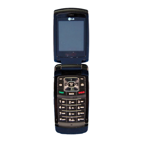
LG KG330 User manual

Date: September, 2006 / Issue 1.0
Service Manual Model : KG330
Service Manual
KG330
KG330 SVC- cover(7.5) 2006.9.19 3:26 PM ˘`1

- 3 -
1. Introduction..................................... 5
1.1 Purpose................................................... 5
1.2 Regulatory Information............................ 5
2. General Performance...................... 7
2.1 Hardware Feature ................................... 7
2.2 Software Feature .................................... 8
3. Technical Brief ................................ 9
3.1 BaseBand Components (TOP) ................9
3.2 Digital Baseband(DBB) Processor.........14
3.3 Analog Main Processor (ABB) ...............15
3.4 Memory ..................................................16
3.5 Power Management Section..................17
3.6. RF Part Technical Brief.........................26
4. Troubleshooting.............................27
4.1 Power On Trouble .................................27
4.2 Charging Trouble ...................................31
4.3 LCD Display Trouble..............................33
4.4 Receiver Trouble....................................35
4.5 Speaker Trouble ....................................38
4.6 Microphone Trouble ...............................41
4.7 Vibrator Trouble .....................................44
4.8 Keypad Backlight Trouble ......................47
4.9 Touch Pad Trouble ................................49
4.10 Jog Encoder Trouble............................51
4.11 Rotary Trouble .....................................53
4.12 SIM Detect Trouble ..............................55
4.13 Earphone Trouble ................................57
4.14 RTC Trouble ........................................64
4.15 Camera Trouble ...................................66
4.16 Camera Flash Trouble .........................69
4.17 MICRO SD Trouble..............................71
4.18 RX Part Trouble Shooting ....................73
4.19 TX Part Trouble Shooting ....................83
5. Downloading Software ..................95
5.1 The Environment of Downloading
Software.................................................95
5.2 The Procedure of Downloading
Software.................................................96
6. BLOCK DIAGRAM........................103
7. Circuit Diagram ............................105
8. Pcb Layout....................................116
9. Calibration ....................................121
9.1 Calibration Equipment Setup ...............121
9.2 Standalone Test...................................124
10. EXPLODED VIEW &
REPLACEMENT PART LIST .... 131
10.1 EXPLODED VIEW ............................ 131
10.2 Replacement Parts
<Mechanic component>.................... 133
<Main component> ........................... 137
10.3 Accessory ......................................... 154
Table of Contents

- 4 -

1. Introduction
- 5 -
1.1. Purpose
This manual provides the information necessary to repair, calibration, description and download the
features of the F9200.
1.2. Regulatory Information
1.2.1. Security
Toll fraud, the unauthorized use of telecommunications system by an unauthorized part (for example,
persons other than your company’s employees, agents, subcontractors, or person working on your
company’s behalf) can result in substantial additional charges you’re your telecommunications
services. System users are responsible for the security of own system. There are may be risks of toll
fraud associated with your telecommunications system. System users are responsible for
programming and configuring the equipment to prevent unauthorized use. LGE does not warrant that
this product is immune from the above case but will prevent unauthorized use of common-carrier
telecommunication service of facilities accessed through or connected to it. LGE will not be
responsible for any charges that result from such unauthorized use.
1.2.2. Incidence of Harm
If a telephone company determines that the equipment provided to customer is faulty and possibly
causing harm or interruption in service to the telephone network, it should disconnect telephone
service until repair can be done. A telephone company may temporarily disconnect service as long as
repair is not done.
1.2.3. Changes in Service
A local telephone company may make changes in its communications facilities or procedure. If these
changes could reasonably be expected to affect the use of the F9200 or compatibility with the network,
the telephone company is required to give advanced written notice to the user, allowing the user to
take appropriate steps to maintain telephone service.
1.2.4. Maintenance Limitations
Maintenance limitations on the F9200 must be performed only by the LGE or its authorized agent.
The user may not make any changes and/or repairs expect as specifically noted in this manual.
Therefore, note that unauthorized alternations or repair may affect the regulatory status of the system
and may void any remaining warranty.
I. Introduction

1. Introduction
- 6 -
1.2.5. Notice of Radiated Emissions
The F9200 complies with rules regarding radiation and radio frequency emission as defined by local
regulatory agencies. In accordance with these agencies, you may be required to provide information
such as the following to the end user.
1.2.6. Pictures
The pictures in this manual are for illustrative purposes only; your actual hardware may look slightly
different.
1.2.7. Interference and Attenuation
An F9200 may interfere with sensitive laboratory equipment, medical equipment, etc. Interference
from unsuppressed engines or electric motors may cause problems.
1.2.8. Electrostatic Sensitive Devices
ATTENTION
Boards, which contain Electrostatic Sensitive Device (ESD), are indicated by the sign. Following
information is ESD handling: Service personnel should ground themselves by using a wrist strap when
exchange system boards.
When repairs are made to a system board, they should spread the floor with anti-static mat which is
also grounded. Use a suitable, grounded soldering iron. Keep sensitive parts in these protective
packages until these are used. When returning system boards or parts such as EEPROM to the
factory, use the protective package as described.

2. General Performance
- 7 -
2.1 Hardware Feature
2. General Performance
Class GPRS Class 10
Radio Tri Band (GSM900/DCS1800/PCS1900)
Camera 1.3M CMOS
Display 2.0 176 x 220 262K TFT
Connectivity Bluetooth Class1, USB
Sound 64 Poly
Battery 1000 mAh (min) Li-Ion
Size / weight 106 x 46.5 x 16mm , 105g

2. General Performance
- 8 -
2.2 Software Feature
• Video Recording
• MMS with Video Attachment
• Touch key(Soft1, Soft2)
• WAP 2.0, JAVA 2.0,
• FR / EFR / HR / AMR
• B/T messenger, Buddy room,
• MP3 player/ MPEC4(Voice)

3. Technical Brief
- 9 -
3. Technical Brief
3.1 BaseBand Components (TOP)
X100
U602
U201
U503
U101
U300
U303
U603
J700
U100
U200
C816
CON200
U200
BAT100
U302
CON201
U100 ABB U503 YMU783
U101 DBB CON200 I/O CONN
U602 256 M NAND X100 RTC
J700 MINI SD SOCKET U303 256 Nor/128Nand
U200 CHARGING CIRCUIT U603 Multimedia IC
U102 LOAD SWITCH C816 Camera Conn
BAT100 Backup Battery U302 Bluetooth module
CON201 SIMM CONN

3. Technical Brief
- 10 -
BaseBand Components (Bottom)
U702
U202
C704
U604
U600
U604 PMIC C704 LCD Conn
U600 MMP LDO U202 Touch LDO
U702 Touch CONN

3. Technical Brief
- 11 -
BaseBand Components (Speaker)
Vibrator
Speaker

3. Technical Brief
- 12 -
BaseBand Components (Sub_Camera)
U100
LD100
CN101
CN100
LD100 Camera Flash U100 Hall switch
CN100 B to B Conn CN101 Camera Conn

3. Technical Brief
- 13 -
BaseBand Components (Touch FPCB)
U100
CN100
U100 Touch Sensor CN100 B to B conn

3. Technical Brief
- 14 -
3.2 Digital Baseband(DBB) Processor
Block diagram of the D751685(Calyso Plus)

3. Technical Brief
- 15 -
3.3 Analog Main Processor (ABB)
Block diagram of the TWL3016

3. Technical Brief
- 16 -
3.4 Memory
• 256 Mbit Nor flash memory + 128Mbit PSRAM
• 16 bit parallel data bus
• ADD01 ~ ADD24
• RF Calibration data and battery calibration data are also stored in Flash memory area.
• 256 Mbit Nand Memory for Multimedia IC

3. Technical Brief
- 17 -
3.5 Power Management Section
• VRDBB: supplies Digital Baseband Processor core
(1.8V, 1.4V, and 1.2V, 170mA)
• VRMEM: supplies external memory and digital
baseband memory interface I/Os (1,8V or 2.8V,
60mA)
• VSIM: supplies the SIM card and SIM card driver
(1.8V or 2.9V, 20mA)
• VRTC: supplies the Real-Time Clock module and
32kHz oscillator located in the digital baseband
during all modes.(1.3V, 1.5V, and !.8V, 10µA)
• VABB: supplies the analog portions of the
TWL3016 (2.8V and 1.8V)
• VIO: supplies thedigital core and I/Os of the
TWL3016 ( 2.8V, 100mA)
• VUSB : supplies the USB interface (3.3V, 15mA)

3. Technical Brief
- 18 -
3.5.1 MIDI
• The ringing source of LG-KG330 is the MIDI IC
• The MIDI chip which is used in LG-KG330 is
YMU 783 from Yamaha.
• YMU783 generates 64-poly MIDI sound & has
DAC converter for I2S Interface for Digital
Sound(MP3 ,WMA ..)
• LG-KG330 uses 8 bit parallel interface.
• Support differential Mono output & stereo
output
• Support 2.8V core & 3.0V or 1.8V I/O interface.

3. Technical Brief
- 19 -
3.5.2 Charging
4.2V ~ 3.87V 3.86V ~ 3.73V 3.72V ~ 3.62V 3.61V ~ 3.35V
• Charging method: CC-CV
• Charger detect voltage: 5.2V
• Charging time: about 2h30m
• Charging current : 700mA
• CV voltage: 4.2V
• Low battery alarm
- Idle : 3.50V
- Call : 3.61V
• Power-off voltage : 3.35V
• Charging temperature ADC range
- ~ -5°C : not charging oper ation.
- -5°C ~ 50°C : charging.
- 50°C ~ : not charging opera tion.

3. Technical Brief
- 20 -
3.5.3 KEY Back-light Illumination
• KEYPAD Back-light Scheme
(GPO_0)
KEY BACKLIGHT
120
R711R710
120
SSC-TWH104-HLS
LD702
SSC-TWH104-HLS
LD706
LD707
SSC-TWH104-HLS
27pC733
C730 27p
R715
120120
R714
120
R713
12K
R719
27pC736
R709
120
1010
R720 R721
120
R708
C732 27p
SSC-TWH104-HLS
LD701
VBAT
27pC734
27pC735
120
R712
LD705
SSC-TWH104-HLS
C731 27p
C729 27p
12KR718
LD703
SSC-TWH104-HLS
SSC-TWH104-HLS
LD704
LD700
SSC-TWH104-HLS
2
3
1
27p
C741
2SC5585
Q700
KEY_BACKLIGHT
3V3_TCH
LD101
SML-A12UT
SML-A12UT LD100
68R101
R100 68
KEY Backlight
TOUCH KEY Backlight

3. Technical Brief
- 21 -
3.5.4 LCD Back-light Illumination
• LCD Back-light Scheme
PMIC(Charge pump, 2 LDOs, DC/DC)
2V6_CAM
C634
1u
VBAT
C630
1u
R618
0
VBAT
1u
C624
1u
C622
1u
C625
R615
10K
VBAT V_IOV_IO
0.1u
C632
19
16
LX
8PGND1
PGND2
17
12 SBN
SCL
13
14 SDA
VEN
11
10 VIN1
VIN2
15
20 VIN3
4
VOUT
22 VREF
29
C1M 9
C1P 5
C2M 7
6
C2P
DIN1 3
2
DIN2
DIN3 1
28
DIN4 26
DIN5
DIN6 25
24
DIN7
18
FB
GND1
27
GND2
23
LDOUT1 21
LDOUT2
SM8150AB-G
U604
BGND
C629
1u
C633
1u
1u
C621
1u
C628
1V8_CAM
C631
0.1u
VLED
CA_FLASH_EN
MLED1
MLED2
MLED3
I2C_CLK
I2C_DATA
LCD Backlight
Table of contents
Other LG Cell Phone manuals