9
ENG
ENGLISH
INSTALLATIONPREPARATION
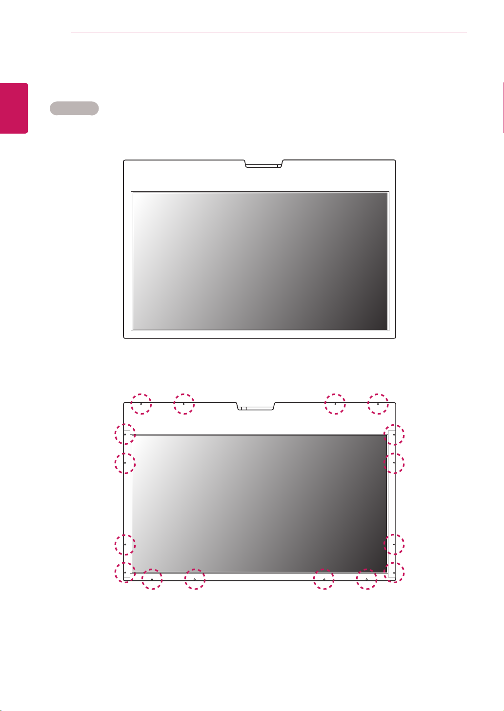
CorrectMethod IncorrectMethod
StorageMethodforPanelProtection
Panel
Cushion
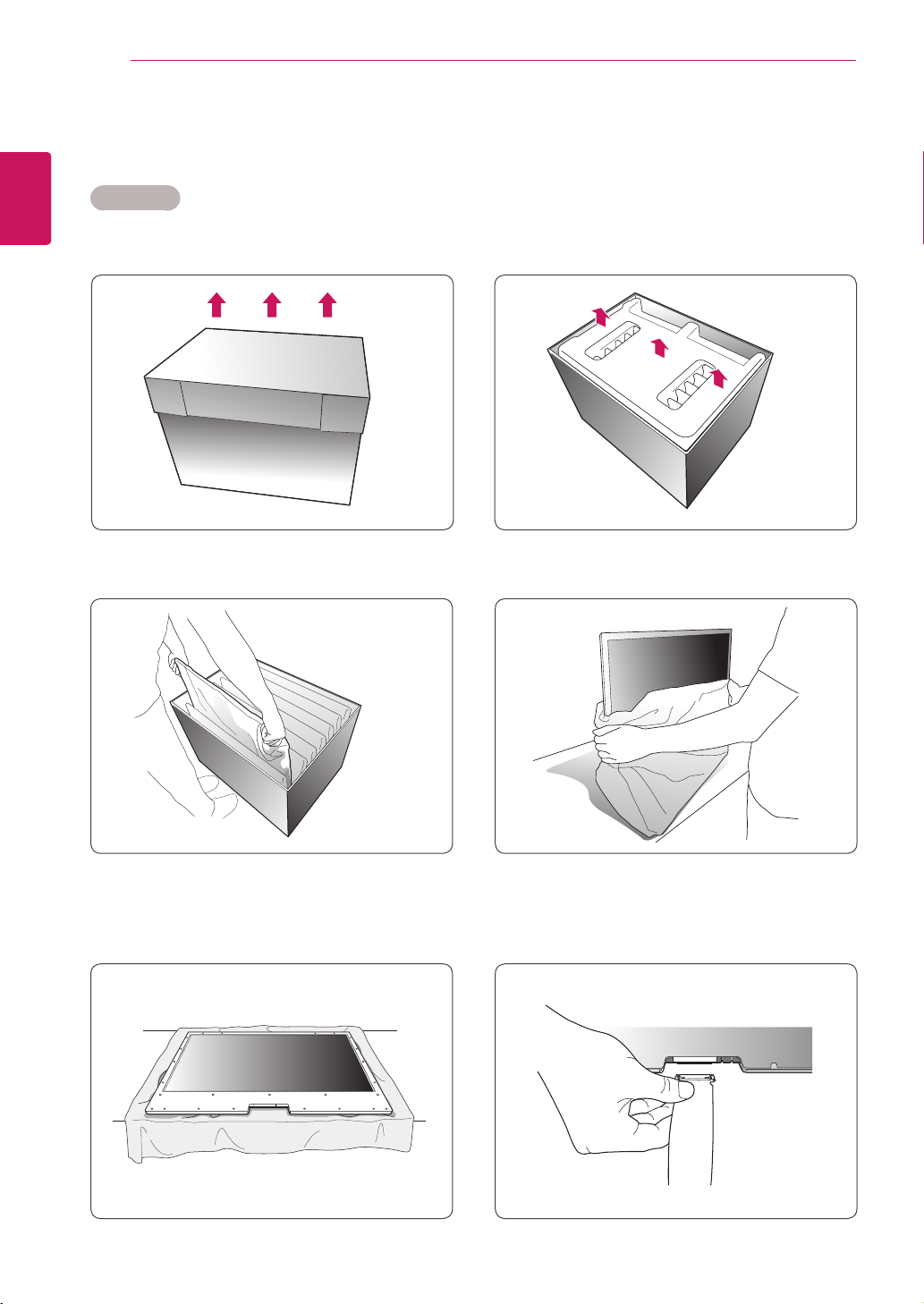
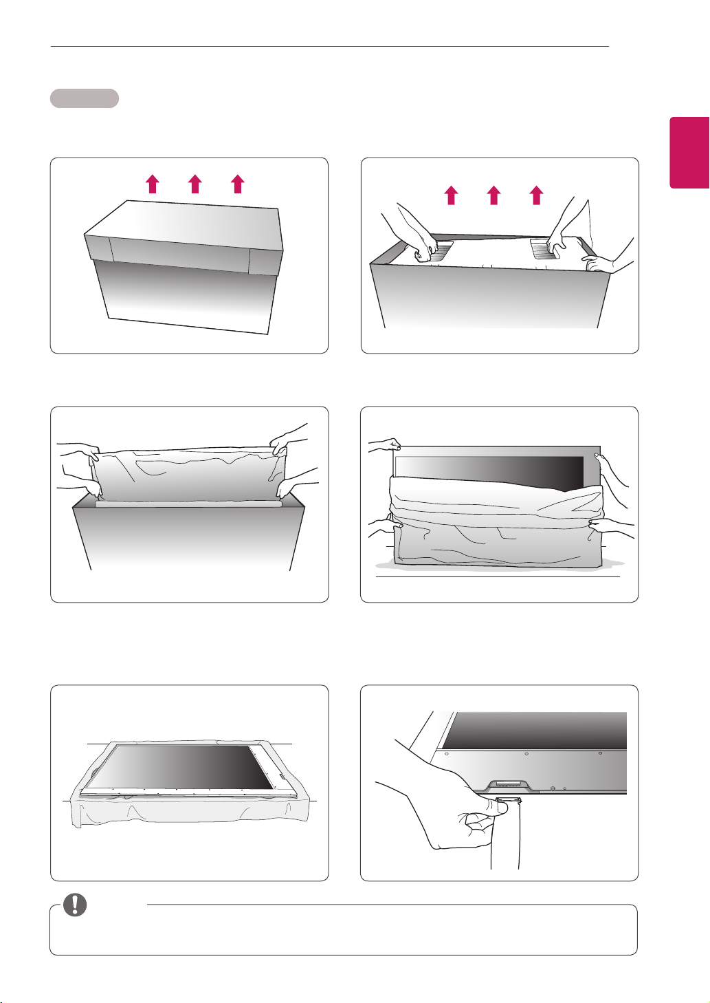
Whenlayingtheproductonaflatfloor,pititface
downonacushionorblankettopreventscratch-
inganddamage.
Ifthereisnoacushionorasoftclothavailable,
ensurethefloorisclean.Thenlaytheproduct
downcarefullywiththepanelfacingeitherupward
ordownward.Atthistime,makesurethatno
objectfallsonthepanel.
Panel
Panel
Panel
Iftheproductistiltedontothebezel,thebottomof
thepanelmaybedamaged.
Iftheproductistiltedontotheedgeofthepanel,
thepanelmaybedamaged.