4
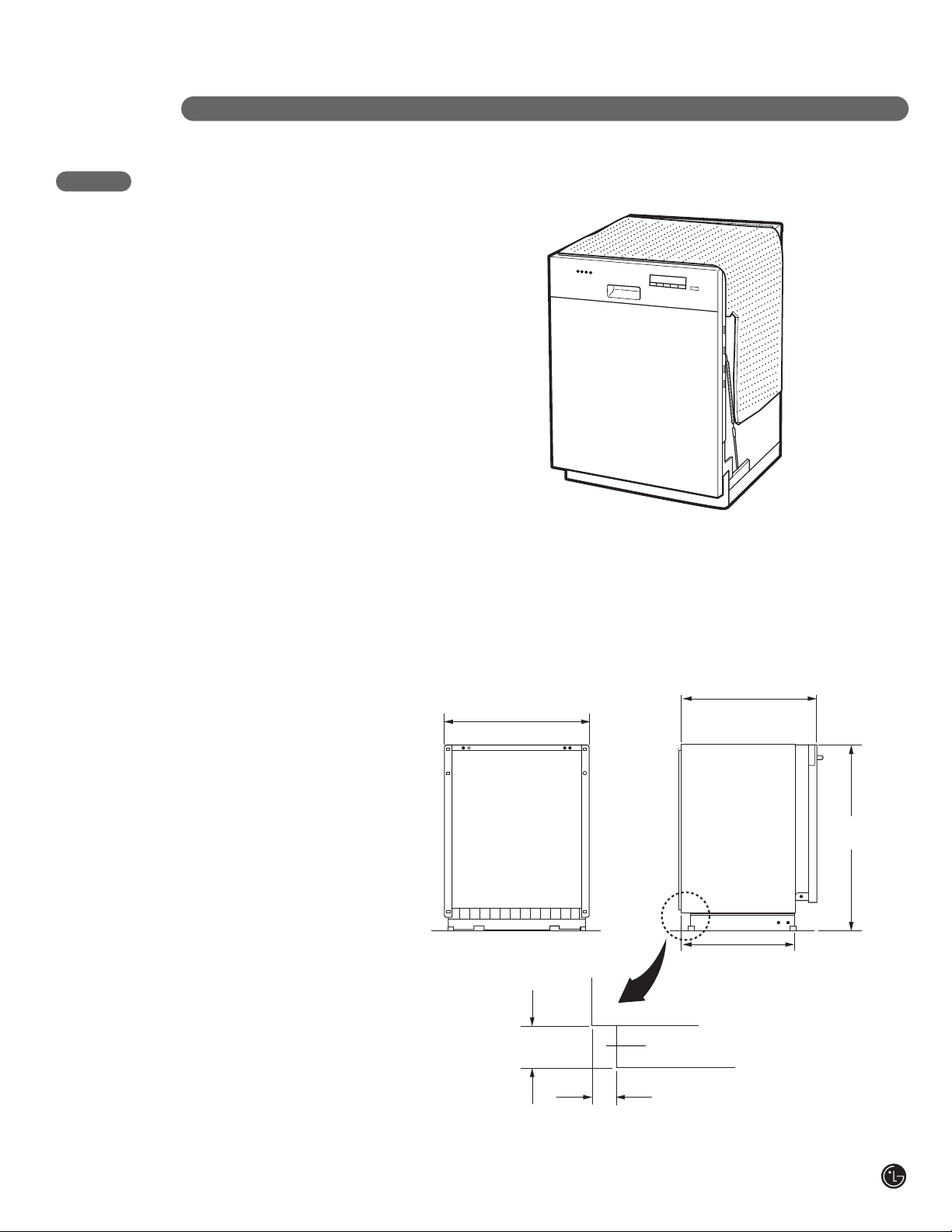
1. This dishwasher is designed to fit a standard
dishwasher opening as shown in Fig. 1.
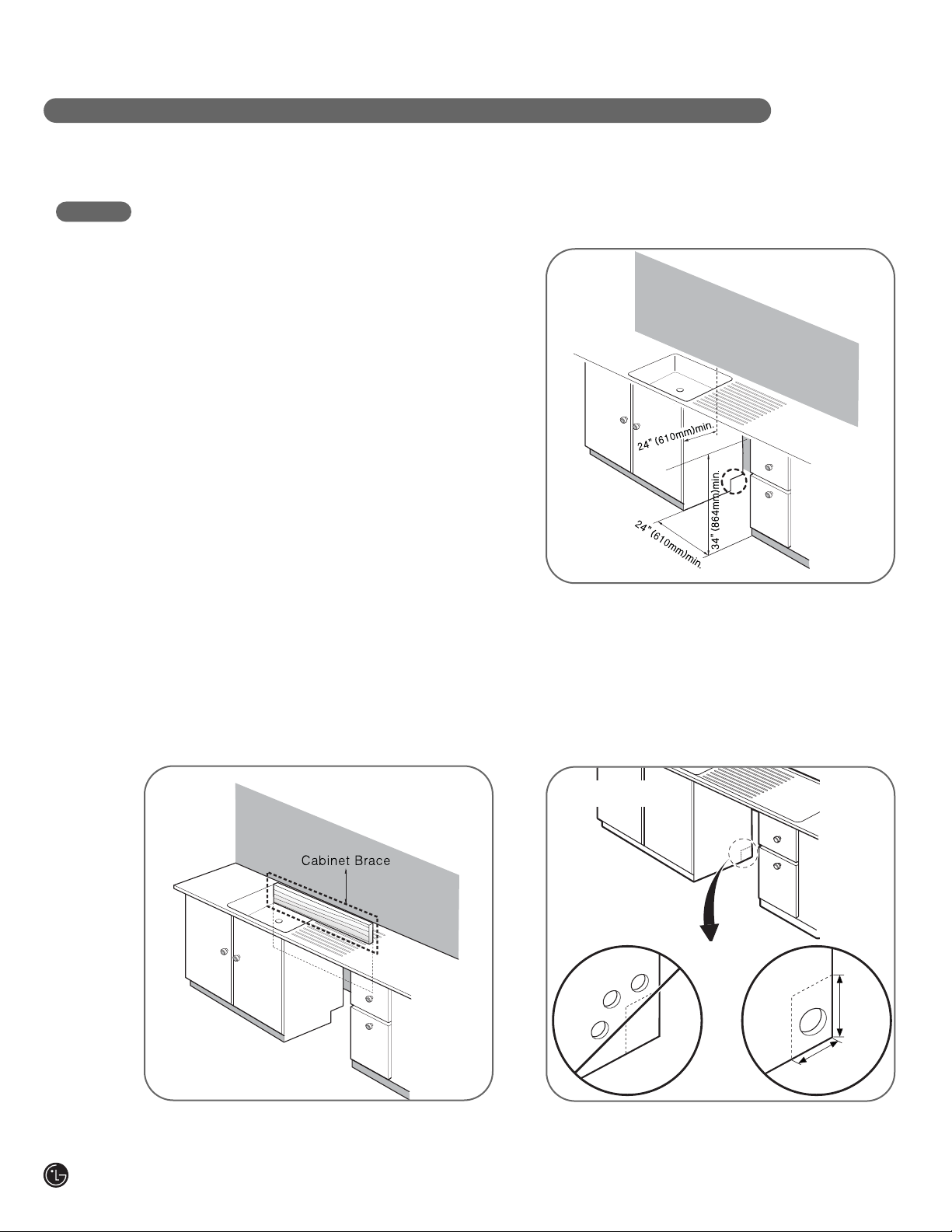
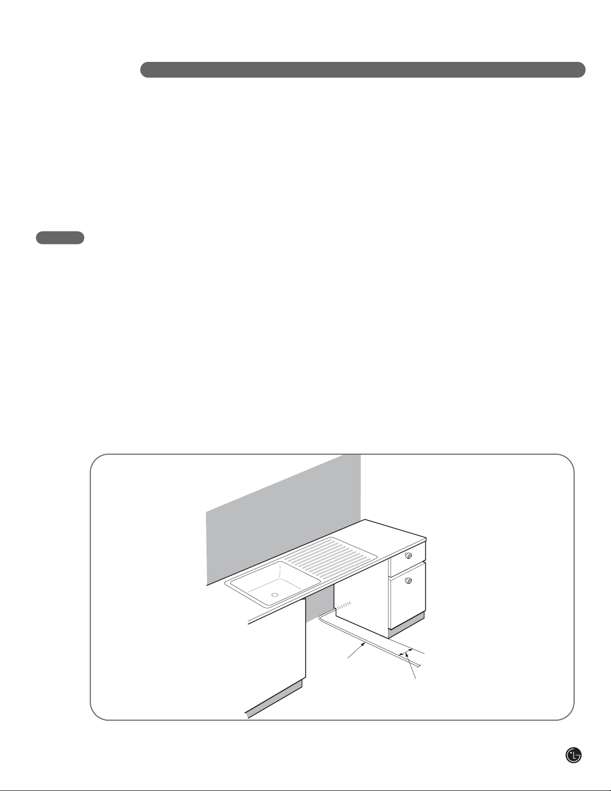
2. Select a location as close to sink as possible for
easy connections to water and drain lines.
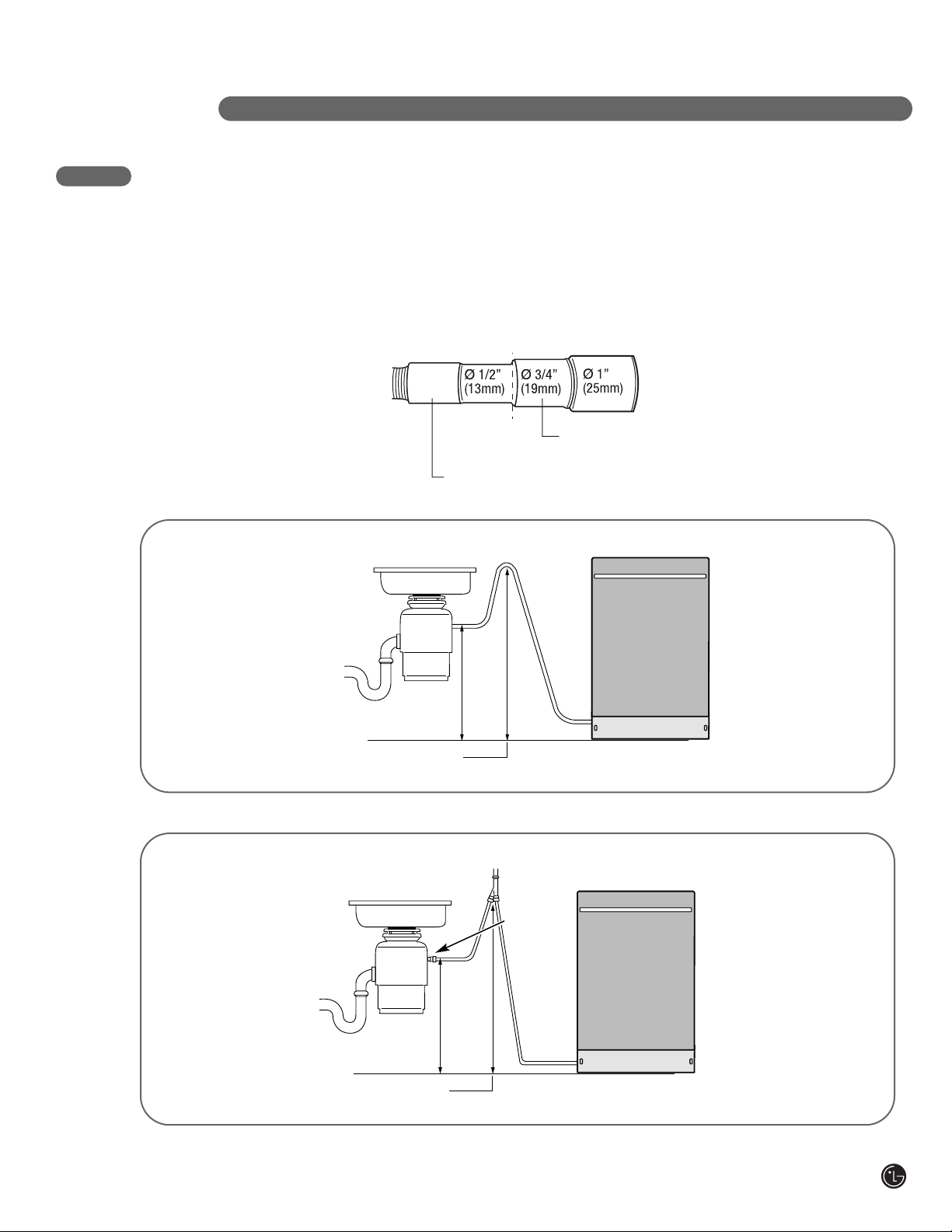
3. To ensure proper drainage, the dishwasher
should not be installed more than 10 ft. (3 m)
from the sink.
4. If dishwasher is to be installed in a corner, a
minimum of 2 in. (50 mm) is required between
the dishwasher and an adjacent wall.
5. To allow for proper clearance of plumbing and
electrical, measure a 4" x 7" target area
(Fig. 3) on the side of the cabinet where the
cabinet meets the back wall. Using a 21⁄2"
diameter hole saw, drill a hole in the target area
within 63⁄4" of the floor, and no more than 3"
from the back wall. If there is a floor in the
cabinet under the sink, it will also be necessary
to drill or cut through the floor to connect the
water and drain under the sink.
NOTES:
• Failure to cut this opening will result in the drain
hose interfering with the rear wall, preventing
flush mount installation.
• Ensure that the floor under the dishwasher is at
the same level as the rest of the room to allow
for any service requirements.
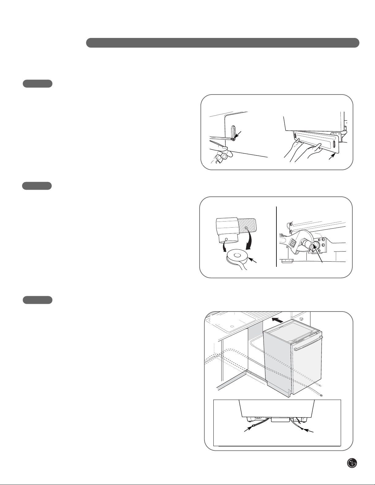
STEP 1: PREPARE CABINET OPENING
INSTALLATION INSTRUCTIONS
For flush installations ONLY, you may remove the
cabinet brace inside the cabinet. An opening (on either side) is required to route
plumbing and electrical connections.
FIG. 1
FIG. 2
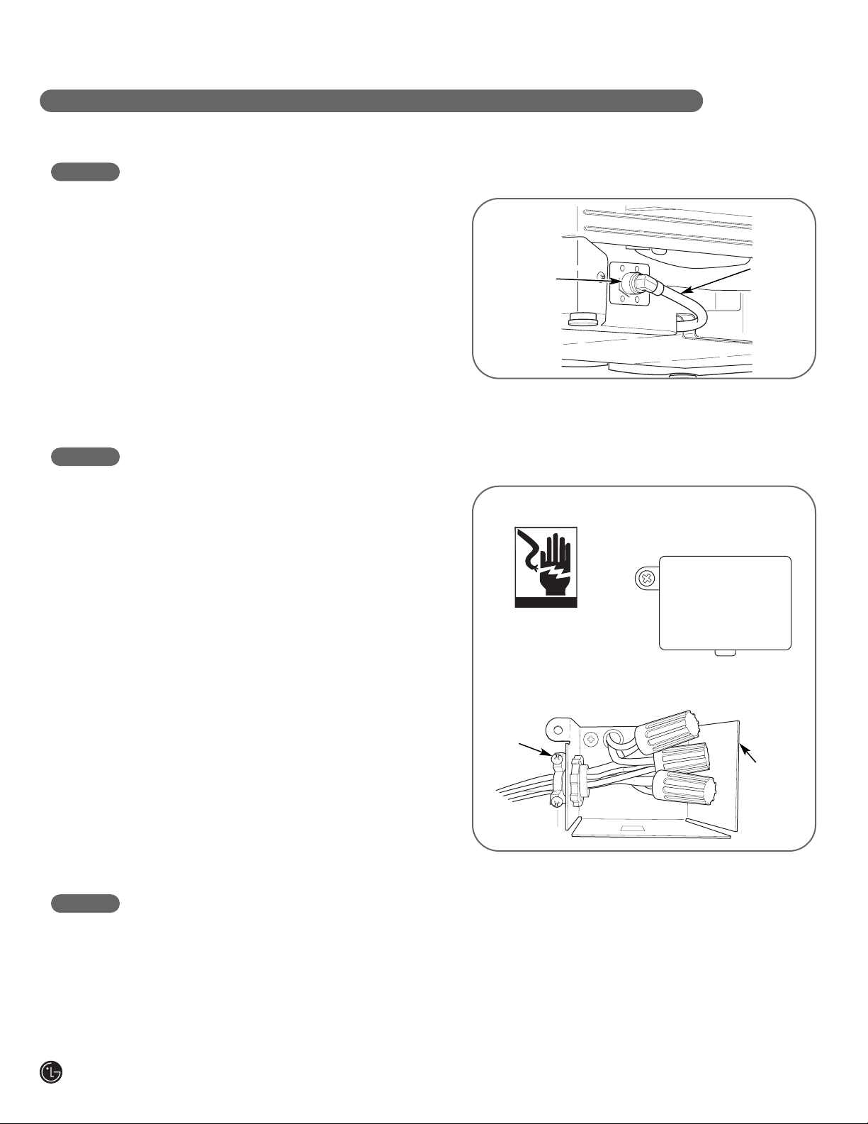
These installation instructions are intended for use by Qualified lnstallers.
FIG. 3
4"
7"