LG 17LS5R-TA User manual

LCD TV
OWNER’S MANUAL
LCD TV MODELS
19LS4R*
22LS4R*
17LS5R*
20LS5R*
Please read this manual carefully before operating your set.
Retain it for future reference.
Record model number and serial number of the set.
See the label attached on the back cover and quote
this information to your dealer when you require service.
ENGLISH


1
ACCESSORIES
Ensure that the following accessories are included with your TV If any accessory is missing, please contact
the dealer where you purchased the product
Owner's
Manual
Owner’s manual
Owner’s Manual Batteries Remote Control
or
Power Cord Cable Management
ACCESSORIES
Polishing Cloth
Polish the screen with the cloth
This feature is not available
for all models.
Slightly wipe stained spot on the exterior only with the cleans-
ing cloths for the product exterior if there is stain or fingerprint on
surface of the exterior.
Do not wipe roughly when removing stain. Please be cautious of
that excessive power may cause scratch or discoloration.

PREPARATION
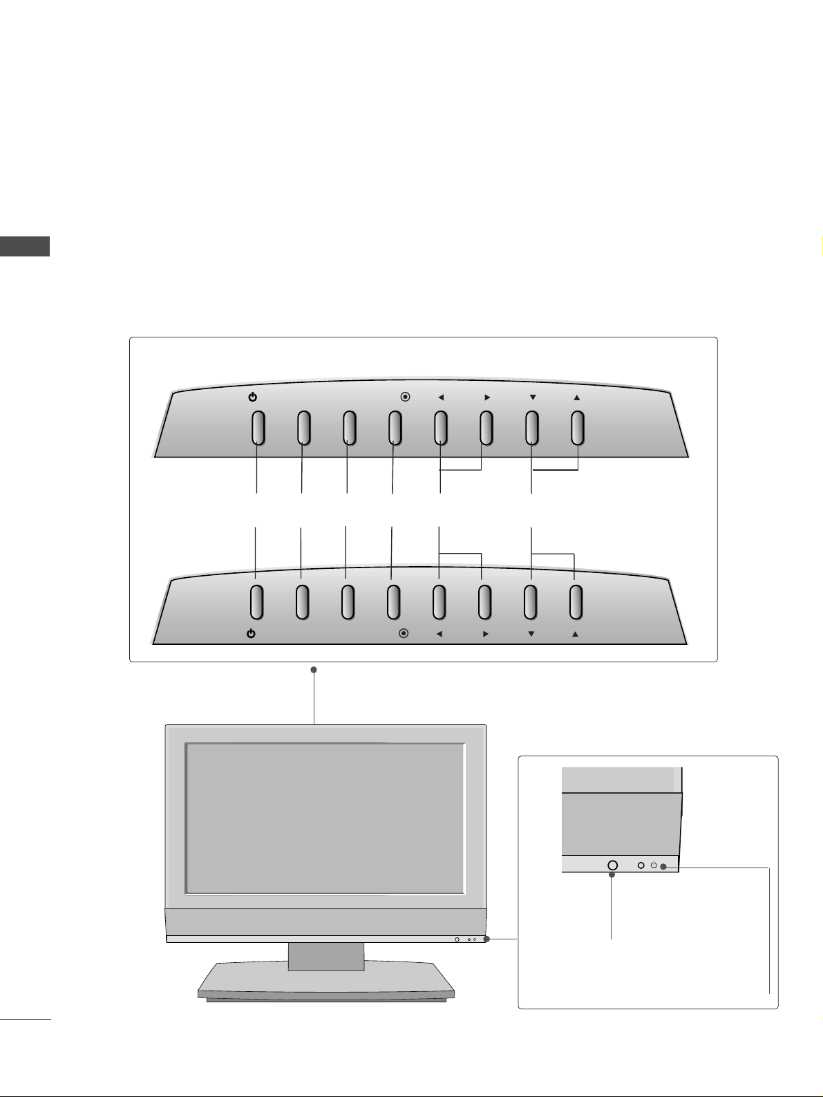
Front Panel Controls....................................................... 4
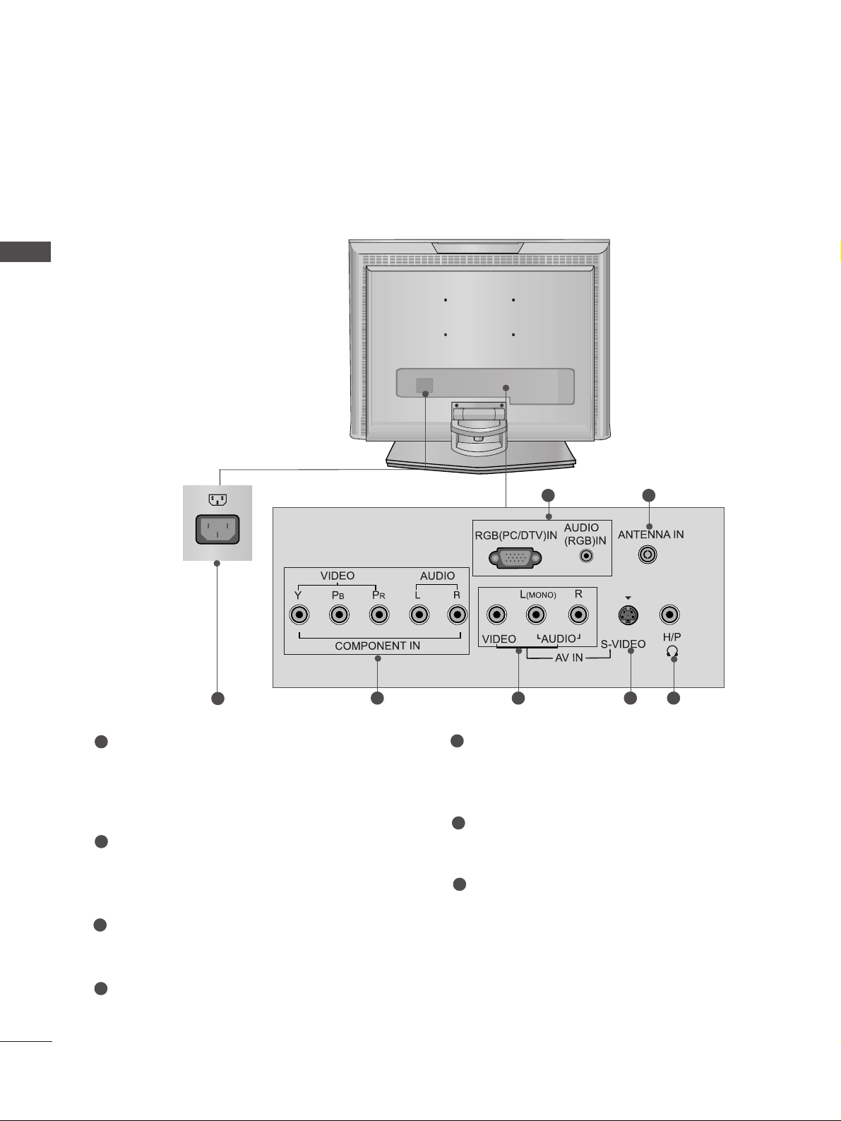
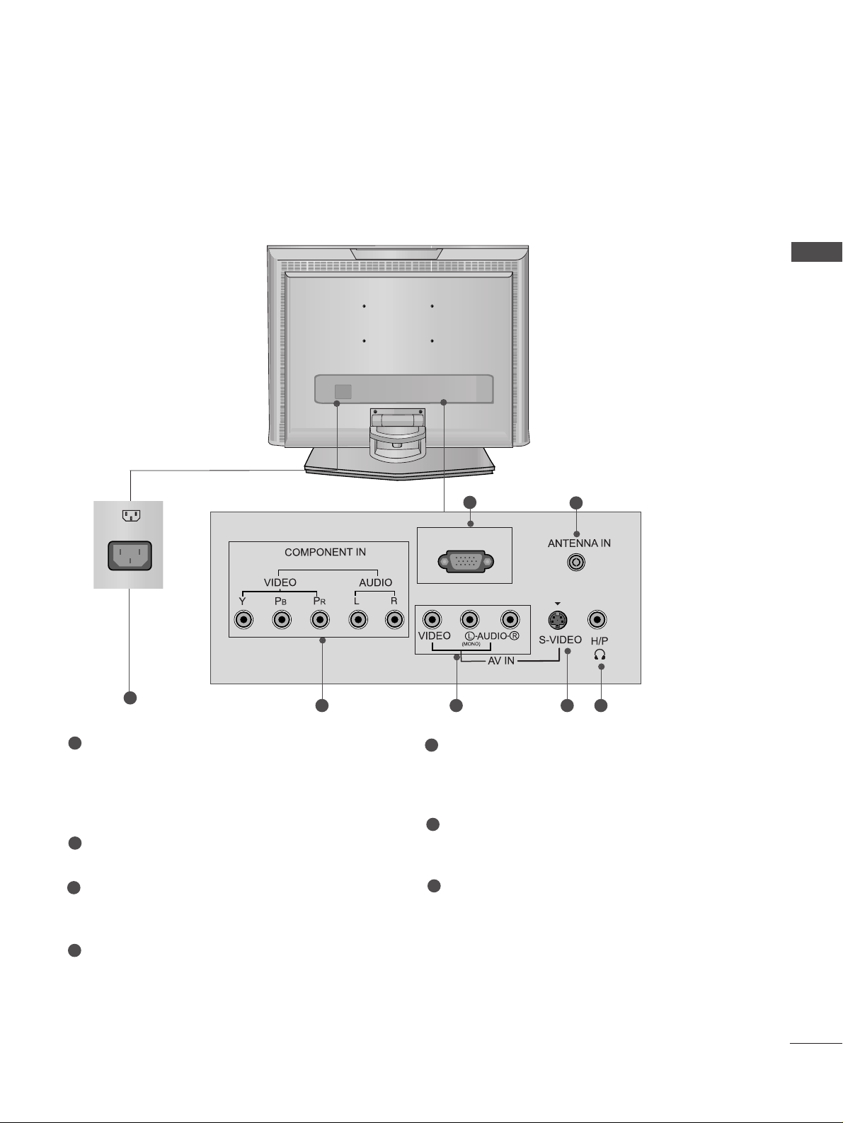
ack Panel Information .................................................. 6
Stand Installation............................................................. 9
Detaching stand..............................................................10
ack Cover for Wire Arrangement ............................ 11
Wall Mount: Horizontal installation.......................... 12
Desktop Pedestal Installation..................................... 12
Positioning your display............................................... 13
Location............................................................................ 13
Kensington Security System ........................................14
Antenna Connection .................................................... 15
PICTURE CONTROL
Picture Size (Aspect Ratio)Control...........................40
Preset Picture Settings
- Picture Mode-Preset..............................................42
- Auto Color Tone Control(Warm/Normal/Cool)
.....43
Manual Picture Adjustment
- Picture Mode-User Option .................................44
- Color Tone - User Option ...................................45
-
Picture Improvement Technology
....................46
Demo...................................................................47
Cinema ..............................................................................48
Picture Reset....................................................................49
SOUND & LANGUAGE CONTROL
Auto Volume Leveler......................................................50
Preset Sound Settings - Sound Mode ......................51
Sound Setting Adjustment - User Mode .................52
alance..............................................................................53
I/II
- Stereo/Dual Reception.........................................54
- NICAM Reception..................................................55
- Speaker Sound Output Selection......................55
ON-SCREEN MENU LANGUAGE SELECTION
............ 56
EXTERNAL EQUIPMENT SETUP
HD Receiver Setup .........................................................16
DVD Setup....................................................................... 18
VCR Setup ...................................................................... 20
Headphone SETUP ........................................................23
PC Setup...........................................................................24
Screen Setup for PC Mode..........................................27
WATCHING TV /PROGRAMME CONTROL
Remote Control Key Functions...................................28
Turning on the TV......................................................... 30
Programme Selection ................................................... 30
Volume Adjustment........................................................30
On Screen Menus Selection and Adjustment.........31
Auto Programme Tuning.............................................. 32
Manual Programme Tuning ......................................... 33
Fine Tuning .......................................................................34
Assigning a Station Name............................................35
Programme Edit ............................................................. 36
Favourite Programme .................................................... 37
Calling the Programme Table..................................... 38
Child lock ........................................................................ 39
PREPARATION PICTURE CONTROL
WATCHING TV / PROGRAMME CONTROL
2
CONTENTS
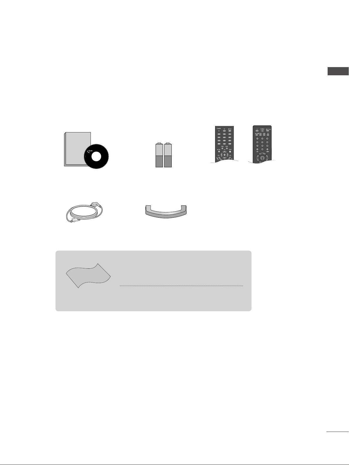
AACCCCEESSSSOORRIIEESS......................................................1
CONTENTS

3
CONTENTS
APPENDIX
Troubleshooting..............................................................64
Maintenance ...................................................................66
Product Specifications ..................................................67
TIME SETTING
Clock Setup......................................................................57
Auto On/Off Timer Setting .........................................58
Sleep Timer Setting........................................................59
Auto Shut-off Setting ....................................................60
TELETEXT
Switch On/Off ...............................................................61
SIMPLE Text .....................................................................61
TOP Text ...........................................................................62
FASTEXT ...........................................................................62
Special Teletext Functions............................................63

4
PREPARATION
FRONT PANEL CONTROLS
PREPARATION
■
This is a simplified representation of the front panel. Here shown may be somewhat different from your TV.
■
If your product has a protection film attached, remove the film and then wipe the product with a polishing
cloth.
17LS5R*/ 20LS5R*
INPUT MENU VOL PR
/I OK
INPUT MENU VOL PR
/I OK
PROGRAMME
Buttons
VOLUME
Buttons
MENU
Button
OK
Button
INPUT
Button
POWER
Button
Remote Control
Sensor
Power/St ndby Indic tor
• illuminates red in standby mode.
• illuminates green when the set is switched on.
17LS5R*
20LS5R*

5
PREPARATION
Remote Control Sensor
Power/Standby Indicator
• illuminates red in standby mode.
• illuminates green when the set is switched on.
19LS4R / 22LS4R
INPUT MENU VOL PR
/I OK
PROGRAMME
Buttons
VOLUME
Buttons
MENU
Button
OK
Button
INPUT
Button
POWER
Button

6
PREPARATION
BACK PANEL INFORMATION
PREPARATION
■
This is a simplified representation of the back panel. Here shown may be somewhat different from your TV.
17LS5R
1
Power Cord Socket
This TV operates on an AC power. The voltage is
indicated on the Specifications page. Never
attempt to operate the TV on DC power.
RGB/Audio Input
Connect the monitor output from a PC/DTV to
the appropriate input port.
Antenna Input
Connect over-the-air signals to this jack.
Component Input
Connect a component video/audio device to
these jacks.
Audio/Video Input
Connect audio/video output from an external
device to these jacks.
S-Video Input
Connect S-Video out from an S-VIDEO device.
Headphone Input
1
2
3
4
5
6
7
17LS5R
2 3
54 6 7

7
PREPARATION
20LS5R*
Power Cord Socket
This TV operates on an AC power. The voltage is
indicated on the Specifications page. Never
attempt to operate the TV on DC power.
SERVICE ONLY
Antenna Input
Connect over-the-air signals to this jack.
Component Input
Connect a component video/a dio device to
these jacks.
Audio/Video Input
Connect a dio/video o tp t from an external
device to these jacks.
S-Video Input
Connect S-Video o t from an S-VIDEO device.
Headp one Input
1
2
3
4
5
6
7
SERVICE ONLY
(480i/480p/576i/576p)
1
AC IN
23
54 6 7

8
BACK PANEL INFORMATION
PREPARATION
PREPARATION
19LS4R / 22LS4R
RGB (PC/DTV) IN
S-VIDEO
AV IN
VIDEO
LR
AUDIO
Y
PB
PR
LR
VIDEO
COMPONENT IN
AUDIO
HDMI/DVI IN
AUDIO
(RGB/DVI) IN
H/P
ANTENNA IN
234
85 6
Power Cord Socket
This TV operates on an AC power. The voltage is
indicated on the Specifications page. Never
attempt to operate the TV on DC power.
HDMI/DVI IN Input
Connect a HDMI signal to HDMI IN.
Or DVI(VIDEO)signal to HDMI/DVI port with DVI
to HDMI cable.
RGB/Audio Input
Connect the monitor output from a PC/DTV to
the appropriate input port.
Antenna Input
Connect over-the-air signals to this jack.
Audio/Video Input
Connect audio/video output from an external
device to these jacks.
Component Input
Connect a component video/audio device to
these jacks.
S-Video Input
Connect S-Video out from an S-VIDEO device.
Headphone Input
1
2
3
4
5
6
7
8
7
1

9
PREPARATION
STAND INSTALLATION
1
Carefully place the product screen side down on a cushioned
surface that will protect product and screen from damage.
■
Here shown may be somewhat different from your TV.
3Place the product stand on the product as shown.
17/20LS5R*
1
Carefully place the product screen side down on a cushioned
surface that will protect product and screen from damage.
19/22LS4R*
2
Assemble parts of stand body with
the product
of the stand.
Insert stand body into
the product
until clicking sound.
stand body
Hold the hhiinnggee bbooddyyand bend it upward.
Hinge Body
Insert the ssttaanndd bbooddyyinto the product until clicking sound.
Stand Body
Assemble the parts of the ssttaanndd bbooddyywith
ccoovveerr bbaasseeof the product.
Cover Base
2
33
4

10
PREPARATION
DETACHING STAND
PREPARATION
12
3
Place the set with its front facing downward on a
cushion or soft cloth.
Pull cover base backward during pressing botton
on stand body.
Hold cover base and pull with shake it backward
to separate from stand body. 4Hold the stand and bend it upward.
5Pull stand body to separate from set during
pressing 2 latches.
■
Here shown may be somewhat different from your TV.

11
PREPARATION
BACK COVER FOR WIRE ARRANGEMENT
Connect the cables as necessary.
To connect an additional equipment, see the EExxtteerrnnaall eeqquuiippmmeennttSSeettuupp section.
1
Install the CCAABBLLEE MMAAAAGGEEMMEETTas shown.
2
First, press the cable management. Hold the CCAABBLLEE MMAAAAGGEEMMEETTwith both hands and pull it upward.
NOTE
!
GGDo not hold the CCAABBLLEE MMAAAAGGEEMMEETT when moving the product.
- If the product is dropped, you may be injured or the product may be broken.
How to remove the cable management
■
Here shown may be somewhat different from your TV.

12
PREPARATION
PREPARATION
DESKTOP PEDESTAL INSTALLATION
For proper ventilation, allow a clearance of 4inches on each side from the wall
WALL MOUNT: HORIZONTAL INSTALLATION
For proper ventilation, allow a clearance of 4" on each side and from the wall Detailed installation
instructions are available from your dealer, see the optional Tilt Wall Mounting Bracket Installation and
Setup Guide
4 inches
4 inches
4 inches 4 inches
4 inches
4 inches
4 inches4 inches
4 inches

13
POSITIONING YOUR DISPLAY
PREPARATION
■
Here shown may be somewhat different from your TV.
Adjust the position of the panel in various ays for maximum comfort.
•• TTiilltt rraannggee
8~12
3
0
10~12
3
0
LOCATION
Position your set so that no bright light or sunlight falls directly onto the screen. Care should be taken
not to expose the set to any unnecessary vibration, moisture, dust or heat. Also ensure that the set is
placed in a position to allo a free flo of air. Do not cover the ventilation openings on the back cover.
If you intend to mount the TV to a all, attach VESA standard mounting interface (optional parts) to the
back of the TV.
When you install the set to use the all mounting bracket (optional parts), fix it carefully so as not to drop.
17/20LS5R* 19/22LS4R*

14
KENSINGTON SECURITY SYSTEM
PREPARATION
PREPARATION
17LS5R*
20LS5R*
19/22LS4R*
- The TV is equipped with a Kensington Security System connector on the back panel Connect the
Kensington Security System cable as shown below
- For the detailed installation and use of the Kensington Security System, refer to the user’s guide provided
with the Kensington Security System
For further information, contact hhttttpp::////wwwwwwkkeennssiinnggttoonnccoomm, the internet homepage of the
Kensington company Kensington sells security systems for expensive electronic equipment such as note-
book PCs and LCD projectors
NOTE
- The Kensington Security System is an optional accessory
NOTES
a If the TV feels cold to the touch, there may be a small “flicker” when when it is turned on
This is normal, there is nothing wrong with TV
b Some minute dot defects may be visible on the screen, appearing as tiny red, green, or blue spots
However, they have no adverse effect on the monitor's performance
c Avoid touching the LCD screen or holding your finger(s) against it for long periods of time
Doing so may produce some temporary distortion effects on the screen

15
ANTENNA CONNECTION
PREPARATION
ANTENNA IN
ANTENNA IN
■For optimum picture quality, adjust antenna direction.
■An antenna cable and converter are not supplied.
Multi-family Dwellings/Apartments
(Connect to wall antenna socket)
Single-family Dwellings /Houses
(Connect to wall jack for outdoor antenna)
Outdoor
Antenna
Wall
Antenna
Socket
RF Coaxial Wire (75 ohm)
Antenna
UHF
Signal
Amplifier
VHF
■In poor signal areas,to get better picture quality, install a signal amplifier to the antenna as shown above.
■If signal needs to be split for two TVs,use an antenna signal splitter for connection.
■To prevent the equipment damage, never plug in any power cords until you have finished connecting all equipment

Connect the SET TOP with the D-Sub output socket to
RRGGBB ((PPCC//DDTTVV)) IINNsocket on the set nd udio c ble of
the SET TOP to the AAUUDDIIOO ((RRGGBB//DDVVII)) IINN.
Press the IINNPPUUTTbutton to select RGB (DTV).
Connect the SET TOP with the D-Sub output socket to RRGGBB
((PPCC//DDTTVV)) IINNsocket on the set nd udio c ble of the SET
TOP to the AAUUDDIIOO ((RRGGBB)) IINN.
Press the IINNPPUUTTbutton to select RGB (DTV).
Connect the SET TOP outputs to the CCOOMMPPOONNEENNTT IINN
VVIIDDEEOOsockets (Y PBPR) on the set.
Connect the udio c ble from the SET TOP to CCOOMMPPOO--
NNEENNTT IINNAAUUDDIIOOsockets of the set.
Press the IINNPPUUTTbutton to select Component.
(19/22LS4R* /17LS5R* :480i/576i/480p/576p/720p/1080i)
(20LS5R*:480i/480p/576i/576p)
2
3
1
16
EXTERNAL EQUIPMENT SETUP
HD RECEIVER SETUP
■To prevent the equ pment damage, never plug n any power cords unt l you have f n shed connect ng all equ pment.
■
Here shown may be somewhat d fferent from your TV.
When connecting with a component cable
Y
P
B
P
R
LR
VIDEO
COMPONENT IN
AUDIO
RGB OUTPUT
RGB (PC/DTV) IN
AUDIO
(RGB/DVI) IN
12
2
1
When connecting with a D-sub 15 pin cable
19/22LS4R*
1 LS5R*
12
2
1

17
EXTERNAL EQUIPMENT SETUP
When connecting with a HDMI(Only 19/22LS4R )
Connect the HDMI output of the digital set-top box to the
HHDDMMII//DDVVII IINNjack on the set.
Select HDMI/DVI (DTV) input source with using the
IINNPPUUTTbutton on the remote control.
2
1
HDMI/DVI IN
1

18
EXTERNAL EQUIPMENT SETUP
DVD SETUP
EXTERNAL EQUIPMENT SETUP
When connecting with a component cable
Y
P
B
P
R
LR
VIDEO
COMPONENT IN
AUDIO
Component Input ports
To get better picture quality, connect a DVD player to the component input ports as shown below
Component ports on the TV
YPBPR
Video output ports
on DVD player
Y
Y
Y
Y
PB
B-Y
Cb
Pb
PR
R-Y
Cr
Pr
Connect the video output sockets (Y Cb Cr, Y Pb Pr, Y -Y
R-Y or Y P PR) of the DVD to the CCOOMMPPOONNEENNTT IINN
VVIIDDEEOO sockets (Y P PR) of the set.
Connect the audio cable from the DVD to CCOOMMPPOONNEENNTT
IINN AAUUDDIIOO sockets of the set.
Press the IINNPPUUTTbutton to select Component.
(19/22LS4R* /17LS5R* :480i/576i/480p/576p/720p/1080i)
(20LS5R*:480i/480p)
Press the PPLLAAYYbutton on the DVD.
The DVD playback picture appears on the screen.
2
3
4
1
12
This manual suits for next models
3
Table of contents
Other LG LCD TV manuals