LG 19LS4R-MA User manual

Please read this manual carefully before operating
your set.
Retain it for future reference.
Record model number and serial number of the set.
See the label attached on the back cover and quote
this information to your dealer
when you require service.
LCD V
OWNER’S MANUAL
LCD V MODELS
19LS4R
22LS4R
P/NO : MFL34797012 (0710-REV01
Printed in Korea
www.lge.com


1
IMPORTANT SAFETY INSTRUCTIONS
WARNING
W
WARNING
Read these instructions.
Keep these instructions.
Heed all warnings.
Follow all instructions.
Do not place the product in direct sunlight or
near heat sources such as heat registers,
stove and so on.
This may cause a fire.
Do not use the product in damp place such
as a bathroom or any place where it is likely
to get wet.
This may cause a fire or could give an electric shock.
Bend antenna cable between inside and out-
side building to prevent rain from flowing in.
This may cause water damaged inside the product and could
give an electric shock.
Earth wire should be connected.
If the earth wire is not connected, there is possible a danger
of electric shock caused by the current leakage.
If grounding methods are not possible, a separate circuit
breaker should be employed and installed by a ualified
electrician.
Do not connect ground to telephone wires, lightning rods
or gas pipe.
Do not placing anything containing li uid on
top of the product.
This may cause a fire or could give an electric shock.
Wet Location Marking :
Apparatus shall not be exposed to dripping or splashing and
no objects filled with li uids, such as vases, shall be placed
on the apparatus.
Do not insert any object into the exhaust vent.
This may cause a fire or could give an electric shock.
Do not place heavy objects on the product.
This may cause serious injury to a child or adult.
Important safety instructions shall e provided with each apparatus. This information shall e given in a separate
ooklet or sheet, or e located efore any operating instructions in an instruction for installation for use and
supplied with the apparatus.
This information shall e given in a language accepta le to the country where the apparatus is intended to e
used.
The important safety instructions shall e entitled “Important Safety Instructions”. The following safety
instructions shall e included where applica le, and, when used, shall e ver atim as follows. Additional safety
information may e included y adding statements after the end of the following safety instruction list. At the
manufacturer’s option, a picture or drawing that illustrates the intent of a specific safety instruction may e
placed immediately adjacent to that safety instruction :
Power
supplier
Short-circuit
breaker
1
4
5
6
7
8
2
3

2
IMPORTANT SAFETY INSTRUCTIONS
WARNING
Do not use water the product while cleaning.
This may cause damaged the product or could give an elec-
tric shock.
In case of smoke or strange smell from the
product, switch it off ,unplug it from the wall
outlet and contact your dealer or service
center.
This may cause a fire or could give an electric shock.
Do not attempt to service the product your-
self. Contact your dealer or service center.
This may cause damaged the product or could give an electric
shock.
Never touch this apparatus or antenna during
a thunder or lighting storm.
This may cause an electric shock.
Never touch the power plug with a wet hand.
This may cause an electric shock.
Disconnect from the mains and remove all
connections before moving.
Do not place the product in a built-in
installation such as a bookcase or rack.
Ventilation re uired.
When installing the product on a table, be
careful not to place the edge of its stand.
This may cause the product to fall, causing serious injury to
a child or adult, and serious damage to the product.
Do not place an outside antenna in the vicinity
of overhead power lines or other electric light
or power circuits.
This may cause an electric shock.
There should be enough distance between an
outside antenna and power lines to keep the
former from touching the latter even when
the antenna falls.
This may cause an electric shock.
Do not pull the cord but the plug when
unplugging.
This may cause a fire.
W
WARNING
W
NOTE
9 1
2
3
4
5
6
7
10
11
12

3
Ensure the power cord doesn’t trail across
any hot objects like a heater.
This may cause a fire or an electric shock.
Do not plug when the power cord or the plug
is damaged or the connecting part of the
power outlet is loose.
This may cause a fire or an electric shock.
Dispose of used batteries carefully to protect
a child from eating them.
In case that it eats them, take it to see a doctor immediately.
When moving the product assembled with
speakers do not carry holding the speakers.
This may cause the product to fall, causing serious injury to
a child or adult, and serious damage to the product.
Unplug this product from the wall outlet
before cleaning. Do not use li uid cleaners or
aerosol cleaners.
This may cause damaged the product or could give an electric
shock.
Contact the service center once a year to
clean the internal part of the product.
Accumulated dust can cause mechanical failure.
The distance between eyes and the screen
should be about 5 - 7 times as long as diag-
onal length of the screen.
If not, eyes will strain.
Unplug the product from the wall outlet when
it is left unattended and unused for long periods
of time.
Accumulated dust may cause a fire or an electric shock from
deterioration or electric leakage.
Only use the specified batteries.
This make cause damaged the product or could give an
electric shock.
Do not allow a impact shock or any objects to
fall into the product, and do not drop onto the
screen with something.
You may be injured or the product can be damaged.
W
NOTE
8
9
10
11
12
13
14
15
16
17
NOTE
!
GGIf the TV feels cold to the touch, there may be a small “flicker” when it is turned on. This is normal, there
is nothing wrong with TV.
Some minute dot defects may be visible on the screen, appearing as tiny red, green, or blue spots. However,
they have no adverse effect on the monitor's performance.
Avoid touching the LCD screen or holding your finger(s) against it for long periods of time. Doing so may pro-
duce some temporary distortion effects on the screen.
On Disposal
a. The fluorescent lamp used in this product contains a small amount of mercury.
b. Do not dispose of this product with general household waste.
c. Disposal of this product must be carried out in accordance to the regulations of your local authority.

4
CONTENTS
WARNING
. . . . . . . . . . . . . . . . . . . . . . . . . . . . . . . . . . . . . . . . . . . . . . . . . . . . 1
Important Safety Instructions . . . . . . . . . . . . . . . . . . . . . . . . . . . . 1
PREPARATION
Accessories . . . . . . . . . . . . . . . . . . . . . . . . . . . . . . . . . . . . . . . . . . . . . . . . . . . . . . 5
Front Panel Information . . . . . . . . . . . . . . . . . . . . . . . . . . . . . . . . . . . . . 6
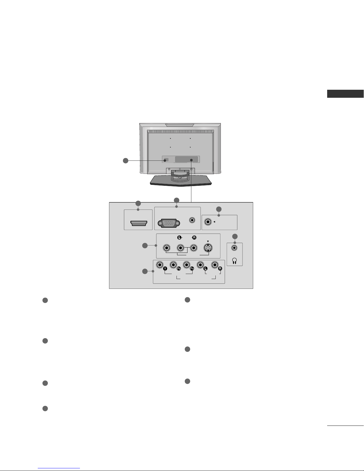
Back Panel Information . . . . . . . . . . . . . . . . . . . . . . . . . . . . . . . . . . . . . . 7
Stand Installation . . . . . . . . . . . . . . . . . . . . . . . . . . . . . . . . . . . . . . . . . . . . . . 8
Detaching Stand . . . . . . . . . . . . . . . . . . . . . . . . . . . . . . . . . . . . . . . . . . . . . . . 9
Back Cover for Wire Arrangement . . . . . . . . . . . . . . . . . . . . . 10
Positioning Your Display . . . . . . . . . . . . . . . . . . . . . . . . . . . . . . . . . . . 11
Desktop Pedestal Installation . . . . . . . . . . . . . . . . . . . . . . . . . . . . 11
Kensington Security System . . . . . . . . . . . . . . . . . . . . . . . . . . . . . 12
Antenna or Cable Connection . . . . . . . . . . . . . . . . . . . . . . . . . . 13
EXTERNAL EQUIPMENT SETUP
HD Receiver Setup . . . . . . . . . . . . . . . . . . . . . . . . . . . . . . . . . . . . . . . . . 14
DVD Setup . . . . . . . . . . . . . . . . . . . . . . . . . . . . . . . . . . . . . . . . . . . . . . . . . . . . . . 17
VCR Setup . . . . . . . . . . . . . . . . . . . . . . . . . . . . . . . . . . . . . . . . . . . . . . . . . . . . . 19
Headphone Setup . . . . . . . . . . . . . . . . . . . . . . . . . . . . . . . . . . . . . . . . . . . 21
PC Setup . . . . . . . . . . . . . . . . . . . . . . . . . . . . . . . . . . . . . . . . . . . . . . . . . . . . . . . . 22
Screen Setup . . . . . . . . . . . . . . . . . . . . . . . . . . . . . . . . . . . . . . . . . . . . . . . . . . 25
- Auto Configure . . . . . . . . . . . . . . . . . . . . . . . . . . . . . . . . . . . . . . . . . 25
- Manual Configure . . . . . . . . . . . . . . . . . . . . . . . . . . . . . . . . . . . . . 26
- Initializing . . . . . . . . . . . . . . . . . . . . . . . . . . . . . . . . . . . . . . . . . . . . . . . . . 27
WATCHING TV / CHANNEL CONTROL
Remote Control Functions . . . . . . . . . . . . . . . . . . . . . . . . . . . . . . . 28
Turning On TV . . . . . . . . . . . . . . . . . . . . . . . . . . . . . . . . . . . . . . . . . . . . . . . . 30
Channel Selection . . . . . . . . . . . . . . . . . . . . . . . . . . . . . . . . . . . . . . . . . . . 30
Volume Adjustment . . . . . . . . . . . . . . . . . . . . . . . . . . . . . . . . . . . . . . . . . 30
On-Screen Menus Selection . . . . . . . . . . . . . . . . . . . . . . . . . . . . . 31
Channel Search . . . . . . . . . . . . . . . . . . . . . . . . . . . . . . . . . . . . . . . . . . . . . . . 32
- Auto Program: Program Search . . . . . . . . . . . . . . . . . . . 32
-
Manual Program: Adding/Deleting Channels
. . . . . 33
Fine Tuning Adjustment . . . . . . . . . . . . . . . . . . . . . . . . . . . . . . . . . . . 34
Favorite Channels Setup . . . . . . . . . . . . . . . . . . . . . . . . . . . . . . . . . . 35
Key Lock . . . . . . . . . . . . . . . . . . . . . . . . . . . . . . . . . . . . . . . . . . . . . . . . . . . . . . . . . 36
PICTURE CONTROL
Picture Size (ARC- Aspect Ratio) Control . . . . . . . . . 37
Preset Picture Settings . . . . . . . . . . . . . . . . . . . . . . . . . . . . . . . . . . . . . 38
- Auto Picture Control (APC) - Preset . . . . . . . . . . 38
- Color Tone - Preset. . . . . . . . . . . . . . . . . . . . . . . . . . . . . . . . . . . 39
Manual Picture Adjustment . . . . . . . . . . . . . . . . . . . . . . . . . . . . . . 40
- Auto Picture Control (APC) - User Mode . . . 40
- Color Tone - User Mode . . . . . . . . . . . . . . . . . . . . . . . . . . . 41
XD - Picture Improvement Technology . . . . . . . . . . . . . 42
XD Demo . . . . . . . . . . . . . . . . . . . . . . . . . . . . . . . . . . . . . . . . . . . . . . . . . . . . . . . 43
Cinema 3:2 Pull down Mode . . . . . . . . . . . . . . . . . . . . . . . . . . . 44
Picture Reset . . . . . . . . . . . . . . . . . . . . . . . . . . . . . . . . . . . . . . . . . . . . . . . . . 45
SOUND & LANGUAGE CONTROL
Digital Auto Sound Processing (DASP) . . . . . . . . . . . . . 46
Sound Setting Adjustment - User Mode . . . . . . . . . . . 47
Auto Volume Leveler (AVL) . . . . . . . . . . . . . . . . . . . . . . . . . . . . . . 48
Balance . . . . . . . . . . . . . . . . . . . . . . . . . . . . . . . . . . . . . . . . . . . . . . . . . . . . . . . . . . 49
Stereo/SAP Broadcasts Setup . . . . . . . . . . . . . . . . . . . . . . . . . . 50
On-Screen Menus Language Selection . . . . . . . . . . . . . . 51
Caption/Text . . . . . . . . . . . . . . . . . . . . . . . . . . . . . . . . . . . . . . . . . . . . . . . . . . 52
TIME SETTING
Clock Setting . . . . . . . . . . . . . . . . . . . . . . . . . . . . . . . . . . . . . . . . . . . . . . . . . . 53
Auto On/Off Timer Setting . . . . . . . . . . . . . . . . . . . . . . . . . . . . . . 54
Sleep Timer Setting . . . . . . . . . . . . . . . . . . . . . . . . . . . . . . . . . . . . . . . . . 55
Auto Shut-off Setting . . . . . . . . . . . . . . . . . . . . . . . . . . . . . . . . . . . . . . . 56
APPENDIX
Troubleshooting . . . . . . . . . . . . . . . . . . . . . . . . . . . . . . . . . . . . . . . . . . . . . . 57
Maintenance . . . . . . . . . . . . . . . . . . . . . . . . . . . . . . . . . . . . . . . . . . . . . . . . . . . 59
Product Specifications . . . . . . . . . . . . . . . . . . . . . . . . . . . . . . . . . . . . . 60

PREPARATION
5
PREPARATION
ACCESSORIES
Ensure that the following accessories are included with your product. If an accessory is missing, please contact
the dealer where you purchased the product.
Ca le Management
1.5V 1.5V
Owner’s Manual
Remote Control
123
456
78
0
9
VOL VOL
CH
CH
ENTER
POWER
MENU REVIEW SLEEP
APC DASP ARC/*
MTS
FCRMUTE
A.PROG
CAPTION
TV INPUT
MEMORY/ERASE
Batteries
Power Cord
* Slightly wipe stained spot on the exterior only with the polishing
cloth for the product exterior if there is stain or fingerprint on
surface of the exterior.
* Do not wipe roughly when removing stain. Please be cautions of
that excessive pressure may cause scratch or discoloration.
Polishing Cloth

PREPARATION
6
FRONT PANEL INFORMATION
PREPARATION
■
Here shown may be somewhat different from your TV.
Front Panel Controls
Remote Control Sensor
Power/Stand y Indicator
Illuminates red in standby mode.
When the TV is turned on, the indicator
blinks green and then illuminates green
before the picture is displayed.
INPUT MENU VOL CH
/I
ENTER
CHANNEL
(EE,DD)Buttons
VOLUME
(FF,GG)Buttons
MENU
Button ENTER
Button
INPUT
Button
POWER
Button
GGIf your product has a protection tape attached, remove the tape.
And then wipe the product with a cloth (If a polishing cloth is included with your product, use it).
NOTE
!

PREPARATION
7
BACK PANEL INFORMATION
HDMI/DVI IN
VIDEO
AUDIO
MONO
()
S-VIDEO
VIDEO
ANTENNA IN
COMPONENT IN
AUDIO
H/P
RGB (PC/DTV) IN
AUDIO
(RGB/DVI) IN
AV IN
1
5
6
2
3
4
( )
Back Connection Panel
7
■
Here shown may be somewhat different from your TV.
HDMI/DVI IN
Connect a HDMI signal to this jack.
Or DVI (Video) signal to this jack with a HDMI to
DVI cable.
RGB (PC/DTV) IN
Connect the output from a PC or DTV.
AUDIO (RGB/DVI) IN
Connect the audio from a PC or DTV.
ANTENNA IN
Connect over-the air signals to this jack.
HEADPHONE INPUT
Plug the headphone into the headphone socket.
AV (Audio/Video) IN
Connect audio/video output from an external
device to these jacks.
S-VIDEO
Connect S-Video out from an S-VIDEO device.
COMPONENT IN
Connect a component video/audio device to these
jacks.
Power Cord Socket
For operation with AC power.
Caution: Never attempt to operate the TV on DC
power.
15
6
7
2
3
4

PREPARATION
8
STAND INSTALLATION
PREPARATION
Insert the SSTTAANNDD BBOODDYYinto the product until clicking sound.
Carefully place the product screen side down on a cushioned surface that will protect product and screen
from damage.
Assemble the parts of the SSTTAANNDD BBOODDYYwith CCOOVVEERR BBAASSEEof the prod-
uct.
SSTTAANNDD BBOODDYY
■
Here shown may be somewhat different from your TV.
3
1
4
Hold the HHIINNGGEE BBOODDYYand bend it upward.
2
HHIINNGGEE BBOODDYY
CCOOVVEERR BBAASSEE

PREPARATION
9
DETACHING STAND
Carefully place the product screen side down on
a cushioned surface that will protect product and
screen from damage.
Pull cover base backward while pressing button
on stand body.
Shake the base while pulling, it will separate from
stand body.
Hold the HHIINNGGEE BBOODDYYand bend it upward.
Pull stand body to separate from set while press-
ing the 2 latches.
■
Here shown may be somewhat different from your TV.
1 2
3
5
4
HHIINNGGEE BBOODDYY

PREPARATION
10
BACK COVER FOR WIRE ARRANGEMENT
PREPARATION
■
Here shown may be somewhat different from your TV.
Connect the cables as necessary.
To connect an additional e uipment, see the EEXXTTEERRNNAALL EEQQUUIIPPMMEENNTTSSEETTUUPPsection.
Install the CCAABBLLEE MMAANNAAGGEEMMEENNTTas shown.
First, press the cable management. Hold the CCAABBLLEE MMAANNAAGGEEMMEENNTTwith both hands and pull it upward.
NOTE
!
GGDo not hold the CCAABBLLEE MMAANNAAGGEEMMEENNTT when moving the product.
- If the product is dropped, you may be injured or the product may be broken.
How to remove the cable management
1
2

PREPARATION
11
POSITIONING YOUR DISPLAY
■
Here shown may be somewhat different from your TV.
■
Adjust the position of the panel in various ways for maximum comfort.
•• TTiilltt rraannggee
10~12
3
0
For proper ventilation, allow a clearance of 10.1cm (4inches) on all four sides from the wall.
GGEnsure ade uate ventilation by following the clearance recommendations.
CAUTION
DESKTOP PEDESTAL INSTALLATION
10.1cm
10.1cm (4 inches
10.1cm 10.1cm

PREPARATION
12
KENSINGTON SECURITY SYSTEM
PREPARATION
- The TV is equipped with a Kensington Security System connector on the ack panel. Connect the
Kensington Security System ca le as shown elow.
- For the detailed installation and use of the Kensington Security System, refer to the user’s guide provided
with the Kensington Security System.
For further information, contact hhttttpp::////wwwwww..kkeennssiinnggttoonn..ccoomm, the internet homepage of the
Kensington company. Kensington sells security systems for expensive electronic equipment such as note-
ook PCs and LCD projectors.
NOTE
- The Kensington Security System is an optional accessory.

PREPARATION
13
ANTENNA OR CABLE CONNECTION
1. Antenna (Analog or Digital
Wall Antenna Socket or Outdoor Antenna without a Cable Box
Connections.
For optimum picture uality, adjust antenna direction if needed.
Wall
Antenna
Socket
Outdoor
Antenna
(VHF, UHF
Multi-family Dwellings/Apartments
(Connect to wall antenna socket
RF Coaxial Wire (75 ohm
Single-family Dwellings /Houses
(Connect to wall jack for outdoor antenna
Be careful not to bend the bronze wire
when connecting the antenna.
Copper Wire
( )
ANTENNA IN
N
( )
ANTENNA IN
GGThe TV will let you know when the analog, cable, and digital channel scans are complete.
NOTE
!
■To improve the picture uality in a poor signal area, please purchase a signal amplifier and install properly.
■If the antenna needs to be split for two TV’s, install a 2-Way Signal Splitter.
■If the antenna is not installed properly, contact your dealer for assistance.
Antenna
UHF
Signal
Amplifier
VHF
2. Cable
Cable TV
Wall Jack
RF Coaxial Wire (75 ohm
( )
ANTENNA IN
N
( )

EXTERNAL EQUIPMENT SETUP
14
EXTERNAL EQUIPMENT SETUP
HD RECEIVER SETUP
To watch digitally roadcast programs, purchase and connect a digital set-top ox.
Y L RPBPR
ANTEN
RGB (PC/DTV) IN
HDMI/DVI IN
AUDIO
(RGB/DVI) IN
MONO
( )
S-VIDEO
VIDEO
AUDIO
AV IN
H/P
VIDEO
AUDIO
COMPONENT IN
When connecting Component cable
1 2
1. How to connect
Connect the video outputs (Y, PB, PR)of the digital set
top box to the CCOOMMPPOONNEENNTT IINN VVIIDDEEOOjacks on
the set. Match the jack colors
(Y = green, PB= blue, and PR= red).
Connect the audio output of the digital set-top box to
the CCOOMMPPOONNEENNTT IINN AAUUDDIIOOjacks on the set.
2
1
2. How to use
■Turn on the digital set-top box.
(Refer to the owner’s manual for the digital set-top box. operation)
■Select CCoommppoonneenntt input source by using the IINNPPUUTT
button on the remote control.
Signal
480i, 480p,
576i, 576p,
720p, 1080i
Component
Yes
■To prevent the equipment damage, never plug in any power cords until you have finished connecting all equipment.

EXTERNAL EQUIPMENT SETUP
15
When connecting with a D-sub 15 pin cable
Connect the RGB output of the digital set-top box to
the RRGGBB ((PPCC//DDTTVV)) IINN jack on the set.
Connect the audio outputs of the set-top box to the
AAUUDDIIOO ((RRGGBB//DDVVII)) IINN jack on the set.
1. How to connect
2. How to use
■Turn on the digital set-top box.
(Refer to the owner’s manual for the digital set-top box.)
■Select RRGGBB--DDTTVV input source with using the IINNPPUUTT
button on the remote control.
2
1
ANTEN
RGB (PC/DTV) IN
HDMI/DVI IN
AUDIO
(RGB/DVI) IN
MONO
( )
S-VIDEO
VIDEO
AUDIO
AV IN
H/P
VIDEO
AUDIO
COMPONENT IN
RGB OUTPUT L R
1 2
When connecting HDMI cable
Connect the digital set-top box to HHDDMMII//DDVVII IINN
jack on the set.
No separated audio connection is necessary.
HDMI supports both audio and video.
1. How to connect
2. How to use
■Turn on the digital set-top box.
(Refer to the owner’s manual for the digital set-top box.)
■Select HHDDMMII//DDVVIIinput source by using the IINNPPUUTT
button on the remote control.
2
1
RGB (PC/DTV) IN
HDMI/DVI IN
AUDIO
(RGB/DVI) IN
MONO
( )
S-VIDEO
VIDEO
AUDIO
AV IN
VIDEO
AUDIO
COMPONENT IN
HDMI-DTV OUTPUT
1
GGWhen connected, the TV will tell a connected device what
resolution it supports and the resolution it prefers. If the
device supports this Auto HDMI function, the player output
resolution will be automatically set to 720p.
GGIf the device does not support Auto HDMI, you need to set
the output resolution appropriately.
NOTE
!

EXTERNAL EQUIPMENT SETUP
16
EXTERNAL EQUIPMENT SETUP
ANTENNA IN
RGB (PC/DTV) IN
HDMI/DVI IN
AUDIO
(RGB/DVI) IN
MONO
( )
S-VIDEO
VIDEO
AUDIO
AV IN
H/P
VIDEO
AUDIO
COMPONENT IN
L R
DVI-DTV OUTPUT
Connect the DVI output of the digital set-top box to the HHDDMMII//DDVVII IINN jack on the set.
Connect the audio output of the digital set-top box to the AAUUDDIIOO ((RRGGBB//DDVVII))IINN jack on the set.
1. How to connect
■Turn on the digital set-top box. (Refer to the owner’s manual for the digital set-top box.)
■Select HHDDMMII//DDVVIIinput source by using the IINNPPUUTTbutton on the remote control.
2. How to use
2
1
1
2
When connecting HDMI to DVI cable

EXTERNAL EQUIPMENT SETUP
17
DVD SETUP
When connecting Component cable
Y L RPBPR
ANTE
RGB (PC/DTV) IN
HDMI/DVI IN
AUDIO
(RGB/DVI) IN
MONO
( )
S-VIDEO
VIDEO
AUDIO
AV IN
H/P
VIDEO
AUDIO
COMPONENT IN
Component Input ports
To get etter picture quality, connect a DVD player to the component input ports as shown elow.
Component ports on the TV
YP
BPR
Video output ports
on DVD player
Y
Y
Y
Y
PB
B-Y
Cb
Pb
PR
R-Y
Cr
Pr
Connect the video outputs (Y, PB, PR)of the DVD to
the CCOOMMPPOONNEENNTT IINN VVIIDDEEOOjacks on the set.
Match the jack colors
(Y = green, PB= blue, and PR= red).
Connect the audio outputs of the DVD to the
CCOOMMPPOONNEENNTT IINN AAUUDDIIOO jacks on the set.
1. How to connect
2. How to use
■Turn on the DVD player, insert a DVD.
■Select CCoommppoonneenntt input source by using the IINNPPUUTT
button on the remote control.
■Refer to the DVD player's manual for operating instructions.
2
1
1 2

EXTERNAL EQUIPMENT SETUP
18
EXTERNAL EQUIPMENT SETUP
When connecting with an S-Video cable
ANTENNA
RGB (PC/DTV) IN
MI/DVI IN
AUDIO
(RGB/DVI) IN
MONO
( )
S-VIDEO
VIDEO
AUDIO
AV IN
H/P
VIDEO
AUDIO
COMPONENT IN
L R S-VIDEO
AUDIO
1
2
Connect the S-VIDEO output of the DVD to the
SS--VVIIDDEEOOinput on the set.
Connect the audio outputs of the DVD to the AAUUDDIIOO
input jacks on the set.
1. How to connect
2. How to use
■Turn on the DVD player, insert a DVD.
■Select AAVV input source by using the IINNPPUUTTbutton on the
remote control.
■Refer to the DVD player's manual for operating instructions.
2
1
RGB (PC/DTV) IN
HDMI/DVI IN
AUDIO
(RGB/DVI) IN
MONO
( )
S-VIDEO
VIDEO
AUDIO
AV IN
VIDEO
AUDIO
COMPONENT IN
HDMI-DVD OUTPUT
1
When connecting HDMI cable
Connect the HDMI output of the DVD to the
HHDDMMII//DDVVII IINNjack on the set.
No separated audio connection is necessary.
HDMI supports both audio and video.
1. How to connect
2. How to use
■Select HHDDMMII//DDVVIIinput source by using the IINNPPUUTT
button on the remote control.
■Refer to the DVD player's manual for operating instructions.
2
1
GGWhen connected, the TV will tell a connected device what
resolution it supports and the resolution it prefers. If the
device supports this Auto HDMI function, the player out-
put resolution will be automatically set to 720p.
GGIf the device does not support Auto HDMI, you need to
set the output resolution appropriately.
To get the best picture uality, adjust the output resolution
of the DVD to 720p.
NOTE
!
This manual suits for next models
3
Table of contents
Other LG LCD TV manuals