LG 26LC2R Series User manual

PPlleeaassee rreeaadd IInnffoorrmmaattiioonn MMaannuuaalliinncclluuddeedd ttooggeetthheerr
bbeeffoorree rreeaaddiinngg tthhiiss mmaannuuaall aanndd ooppeerraattiinngg yyoouurr sseett..
Retain it for future reference.
Record model number and serial number of the set.
See the label attached on the back cover and quote
this information to your dealer when you require service.
P/ O : 38289U0323G (0602-REV00)
Printed in Korea
LCD TV PLASMA TV
OWNER’S MANUAL
LCD TV MODELS
26LC2R*
32LC2R*
PLASMA TV MODELS
42PC1RV*
42PC3RV*


1
ACCESSORIES
ACCESSORIES
Ensure that the following accessories are included with your TV. If an accessory is missing, please contact the
dealer where you purchased the product.
User Guide
Owner’s Manual Batteries
OK
INPUT
TV
TV
INPUT
PIPPR-PIP PR+
PIPINPUT
DVD
ARC
EXIT
VOL
TIME
REVEAL
INDEX
Q.VIEW
MUTE
PR
SLEEP
LIST
I/II
MENU
TEXTPIP SIZE
POSTION
VCR
POWER
123
456
789
*
FAV
?
0
Remote Control Power Cord
2-Wall brackets 2-eye-bolts
2- V brackets
2-Wall brackets
2-bolts
oorr 2266LLCC22RR**,, 3322LLCC22RR**
oorr 4422PPCC11RRVV**,, 4422PPCC33RRVV**
4-bolts for stand assembly
3322LLCC22RR**oonnllyy
Cable
Management
wister Holder
Arrange the wires
with the twister holder.
2-bolts for stand assembly
Refer to p.12
0323G_1-en_rev01 2/28/06 4:12 PM Page 1

2
CON EN S
CONTENTS
ACCESSORIES . . . . . . . . . . . . . . . . . . . . . . . . . . . . . . . . . . . . . . . . . . .1
IN RODUC ION
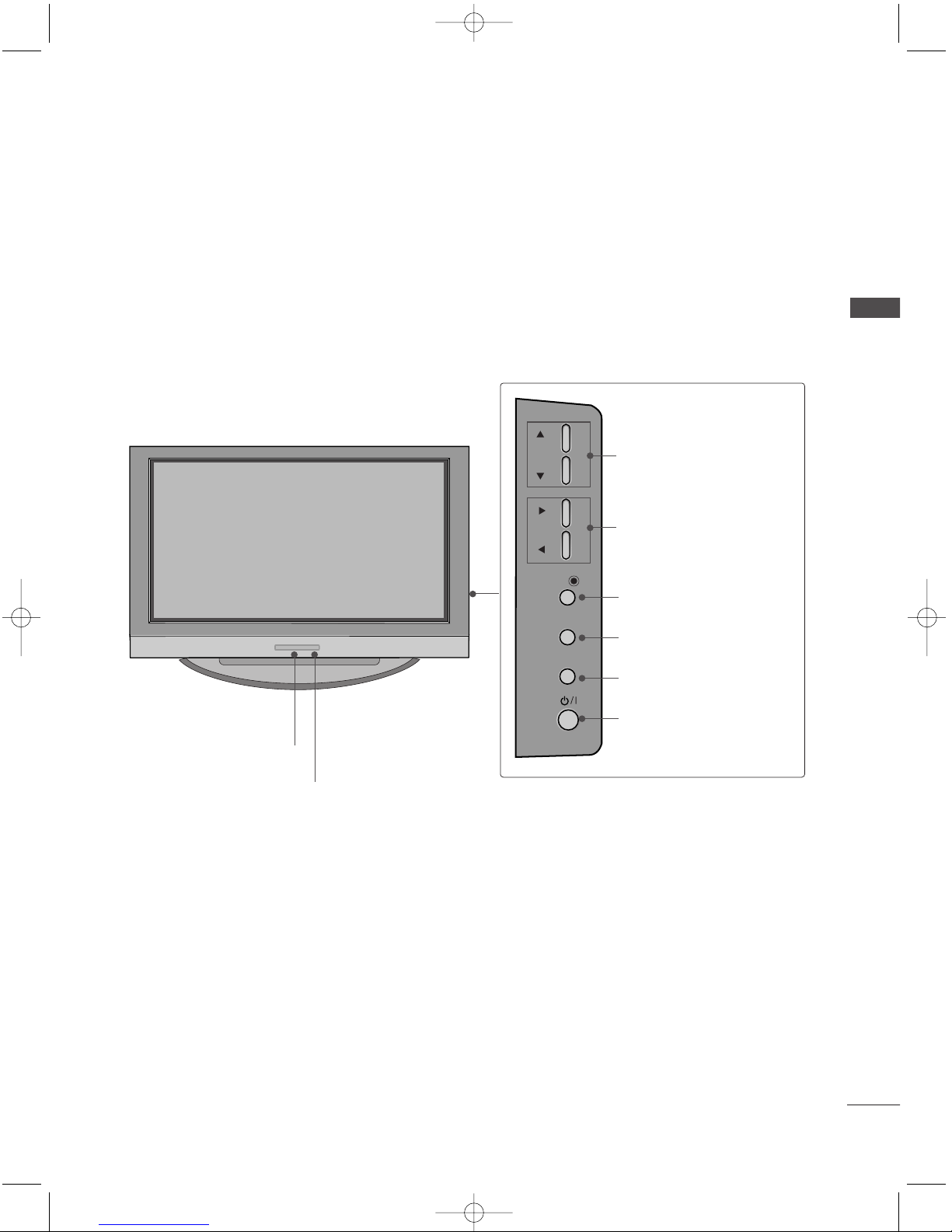
Controls / Connection Options . . . . . . . . . . . . . . . . . . . . . . . . . .4-9
Remote Control Key Functions . . . . . . . . . . . . . . . . . . . . . . . . .10-11
Installing Batteries . . . . . . . . . . . . . . . . . . . . . . . . . .11
V MENU
On Screen enus Selection and Adjustment . . . . .34
SSeettttiinngg uupp TTVV ssttaattiioonnss
Auto programme tuning . . . . . . . . . . . . . . . . . . . . . . . . . . . . . . .35
anual programme tuning . . . . . . . . . . . . . . . . . . . . . . . . . . . .36
Fine tuning . . . . . . . . . . . . . . . . . . . . . . . . . . . . . . . . . . . . . . . . . . . . . . . . . .37
Assigning a station name . . . . . . . . . . . . . . . . . . . . . . . . . . . . . . .38
Programme edit . . . . . . . . . . . . . . . . . . . . . . . . . . . . . . . . . . . . . . . . . . .39
Favourite programme
. . . . . . . . . . . . . . . . . . . . . . . . . . . . . . . . . . . .
40
Calling the programme table
. . . . . . . . . . . . . . . . . . . . . . . . .
41
PPiiccttuurree eennuu OOppttiioonnss
PS (Picture Status emory) . . . . . . . . . . . . . . . . . . . . . .42
Picture Adjustment (PS -User option) . . . . . . . . .43
CS (Colour Status emory) . . . . . . . . . . . . . . . . . . . . . .44
anual Colour Temperature Control
(CS - User option) . . . . . . . . . . . . . . . . . . . . . . . . . . . . . . . . . . . .45
Function . . . . . . . . . . . . . . . . . . . . . . . . . . . . . . . . . . . . . . . . . . .46
ADVANCED-CINE A . . . . . . . . . . . . . . . . . . . . . . . . . . . . . . . . . . .47
ADVANCED-BLACK LEVEL . . . . . . . . . . . . . . . . . . . . . . . . . . . .48
Reset . . . . . . . . . . . . . . . . . . . . . . . . . . . . . . . . . . . . . . . . . . . . . . . . . . . . . . . . . . .49
SSoouunndd eennuu OOppttiioonnss
SS (Sound Status emory) . . . . . . . . . . . . . . . . . . . . . . .50
Sound Frequency Adjustment
(SS - User option) . . . . . . . . . . . . . . . . . . . . . . . . . . . . . . . . . . . .51
AVL (Auto Volume Leveler) . . . . . . . . . . . . . . . . . . . . . . . . . . .52
Balance Adjustment . . . . . . . . . . . . . . . . . . . . . . . . . . . . . . . . . . . . .53
Speaker . . . . . . . . . . . . . . . . . . . . . . . . . . . . . . . . . . . . . . . . . . . . . . . . . . . . . . .54
Stereo/Dual Reception . . . . . . . . . . . . . . . . . . . . . . . . . . . . . . . . .55
NICA Reception . . . . . . . . . . . . . . . . . . . . . . . . . . . . . . . . . . . . . . . .56
Speaker Sound Output Selection . . . . . . . . . . . . . . . . . .56
TTiimmee eennuu OOppttiioonnss
Clock Setup . . . . . . . . . . . . . . . . . . . . . . . . . . . . . . . . . . . . . . . . . . . . . . . . .57
On/Off Time . . . . . . . . . . . . . . . . . . . . . . . . . . . . . . . . . . . . . . . . . . . . . . .58
Auto Sleep . . . . . . . . . . . . . . . . . . . . . . . . . . . . . . . . . . . . . . . . . . . . . . . . . .59
Sleep Timer . . . . . . . . . . . . . . . . . . . . . . . . . . . . . . . . . . . . . . . . . . . . . . . . .59
SSppeecciiaall eennuu OOppttiioonnss
Child Lock . . . . . . . . . . . . . . . . . . . . . . . . . . . . . . . . . . . . . . . . . . . . . . . . . . .60
IS (Image Sticking inimization) ethod . . .61
Low Power . . . . . . . . . . . . . . . . . . . . . . . . . . . . . . . . . . . . . . . . . . . . . . . . . . .62
XD Demo . . . . . . . . . . . . . . . . . . . . . . . . . . . . . . . . . . . . . . . . . . . . . . . . . . . .63
INS ALLA ION
Stand Installation . . . . . . . . . . . . . . . . . . . . . . . . . . . . . . . . . . . . . . . . . . . .12-13
Basic Connection /
How to Remove the Cable anagement . . . . . . . . . . .14-15
How to join the product assembly to the wall
to protect the set tumbling . . . . . . . . . . . . . . . . . . . . . . . . . . . . . . . . . . .17
CONNEC IONS & SE UP
Antenna Connection . . . . . . . . . . . . . . . . . . . . . . . . . . . . . . . . . . . . . . . . . . . .18
VCR Setup . . . . . . . . . . . . . . . . . . . . . . . . . . . . . . . . . . . . . . . . . . . . . . . . . . . . .19-20
External Equipment Connections . . . . . . . . . . . . . . . . . . . . . . . . . .21
DVD Setup . . . . . . . . . . . . . . . . . . . . . . . . . . . . . . . . . . . . . . . . . . . . . . . . . . . . .22-23
HDSTB Setup . . . . . . . . . . . . . . . . . . . . . . . . . . . . . . . . . . . . . . . . . . . . . . . . .24-25
PC Setup . . . . . . . . . . . . . . . . . . . . . . . . . . . . . . . . . . . . . . . . . . . . . . . . . . . . . . .26-27
Turning the TV On . . . . . . . . . . . . . . . . . . . . . . . . . . . . . . . . . . . . . . . . . . . . . . .28
SPECIAL FUNC IONS
PPIIPP ((PPiiccttuurree--IInn--PPiiccttuurree))
Watching PIP . . . . . . . . . . . . . . . . . . . . . . . . . . . . . . . . . . . . . . . . . . . . . . .29
Programme Selection for Sub Picture . . . . . . . . . . . .29
Input Source Selection for Sub Picture . . . . . . . . .30
Sub Picture Size Adjustment (PIP mode only) . .30
oving the Sub Picture (PIP mode only) . . .30
TTeelleetteexxtt
Teletext Language Selection . . . . . . . . . . . . . .31
Switch on/off . . . . . . . . . . . . . . . . . . . . . . . . .31
SI PLE Text . . . . . . . . . . . . . . . . . . . . . . . . . .31
TOP Text . . . . . . . . . . . . . . . . . . . . . . . . . . . . .32
FASTEXT . . . . . . . . . . . . . . . . . . . . . . . . . . . . .32
Special Teletext Functions . . . . . . . . . . . . . . .33
0323G_1-en_rev01 2/28/06 4:12 PM Page 2

3
CONTENTS
V MENU
SSccrreeeenn eennuu OOppttiioonnss
Auto adjustment (RGB [PC] mode only) . . . . . . . . . . .64
anual Configure . . . . . . . . . . . . . . . . . . . . . . . . . . . . . . . . . . . . . . . .65
Setting the Picture Format . . . . . . . . . . . . . . . . . . . . . .66-67
Selecting Wide VGA/XGA mode . . . . . . . . . . . . . . . . . . .68
Initializing
(Reset to original factory settings) . . . . . . . . . . . . . . . .69
APPENDIX
Programming the Remote
. . . . . . . . . . . . . . . . . . . . . . . . . . . . . . . . . .
70
Programming code
. . . . . . . . . . . . . . . . . . . . . . . . . . . . . . . . . . . . .
70-71
Troubleshooting Checklist
. . . . . . . . . . . . . . . . . . . . . . . . . . .
72-73
aintenance
. . . . . . . . . . . . . . . . . . . . . . . . . . . . . . . . . . . . . . . . . . . . . . . . . .
74
Product Specifications
. . . . . . . . . . . . . . . . . . . . . . . . . . . . . . . . . . . . .
75
External Control Device Setup
. . . . . . . . . . . . . . . . . . . . . . . . . . .
76
IR Codes
. . . . . . . . . . . . . . . . . . . . . . . . . . . . . . . . . . . . . . . . . . . . . . . . . . . . . . .
83
Remote control ir codes
. . . . . . . . . . . . . . . . . . . . . . . . . . . . . . . . . . .
84
0323G_1-en_rev01 2/28/06 4:12 PM Page 3

4
CONTROLS
INTRODUCTION
INTRODUCTION
This is the front panel of models 42PC1RV*TVs.
■
This is a simplified representation of the front panel. Here shown may be somewhat different from your TV.
Front Panel Controls
PR
VOL
OK
MENU
INPUT
PROGRAMME Buttons
VOLUME Buttons
MENU Button
OK Button
INPUT Button
POWER Button
PR
VOL
OK
MENU
INPUT
Power/Standby Indicator
• illuminates red in standby mode.
• illuminates white when the set is
switched on.
PR
VOL
OK
MENU
INPUT
0323G_1-en_rev01 2/28/06 4:12 PM Page 4

5
INTRODUCTION
This is the front panel of models 42PC3RV*TVs.
■
This is a simplified representation of the front panel. Here shown may be somewhat different from your TV.
Front Panel Controls
PR
VOL
OK
MENU
INPUT
Remote Control Sensor
Power/Standby Indicator
• illuminates red in standby mode.
• illuminates white when the set is switched on.
PROGRAMME Buttons
VOLUME Buttons
OK Button
MENU Button
INPUT Button
ON/O Button
0323G_1-en_rev01 2/28/06 4:12 PM Page 5

6
CONNECTION OPTION
INTRODUCTION
INTRODUCTION
This is the back panel of models 42PC1RV*, 42PC3RV*TVs.
Back Connection Panel
AUDIO Input
Connections are available for listening
stereo sound from an external device.
VIDEO Input
Connects the video signal from a video
device.
AV IN 2V IN 2
L/MONO
R
AUDIOAUDIO
VIDEOVIDEO
COMPONENT INCOMPONENT IN
RGB INRGB IN
(PC/DTV)
RS-232C INRS-232C IN
(CONTROLOL
&
SERVICE)
REMOTE
CONTROL IN
AUDIO IN
(RGB)
ANTENNA
IN
1
2
VIDEOVIDEO
AUDIOUDIO
AV OUTV OUT
AUDIO OUT
VARIABLE
AC IN
MONO
()
AUDIOUDIO
VIDEOVIDEO
S-VIDEO
AV IN 1V IN 1
HDMI IN
1 5
1110
9
8
2 43
7
6
42PC1RV*only
Component1/2 Input
Connect a component video/audio device to
these jacks.
Remote Control Port
Connect your wired remote control here.
RGB/Audio Input
Connect the monitor output from a PC to the
appropriate input port.
HDMI Input
Connect a HD I signal to HD I port with HD I
cable.
Power Cord Socket
This TV operates on an AC power. The voltage is
indicated on the Specifications page. Never
attempt to operate the TV on DC power.
AV Output
Connect second TV or monitor to the AV OUT
socket on the set.
S-Video Input
Connect S-Video out from an S-VIDEO device.
Audio/Video Input
Connect audio/video output from an external
device to these jacks.
RS-232C Input (CONTROL&SERVICE) Port
Connect the serial port of the control devices to
the RS-232C jack.
Variable Audio Output
Connect an external amplifier or add a subwoofer
to your surround sound system.
Antenna Input
Connect over-the-air signals to this jack.
1
2
3
4
7
5
6
8
9
10
11
0323G_1-en_rev01 2/28/06 4:12 PM Page 6

7
INTRODUCTION
This is the front panel of models 26LC2R*, 32LC2R*TVs.
■
This is a simplified representation of the front panel. Here shown may be somewhat different from your TV.
Front Panel Controls
PR
VOL
OK
MENU
INPUT
R
/I
Remote Control Sensor
Power/Standby Indicator
• illuminates red in standby mode.
• illuminates white when the set is switched on.
PROGRAMME Buttons
VOLUME Buttons
OK Button
MENU Button
INPUT Button
ON/O Button
0323G_1-en_rev01 2/28/06 4:12 PM Page 7

8
CONTROLS
INTRODUCTION
This is the back panel of models 26LC2R*TVs.
AV IN 2V IN 2
AUDIOAUDIOVIDEOVIDEO
L/MONO
R
AC IN
COMPONENT INCOMPONENT IN
RGB INRGB IN
(PC/DTV)
RS-232C INRS-232C IN
(CONTROL
&
SERVICE)
REMOTE
CONTROL IN
AUDIO IN
(RGB)
ANTENNA
IN
1
2
VIDEOVIDEO
AUDIOUDIO
AV OUTV OUT
AUDIO OUT
VARIABLE
AC IN
MONO
()
AUDIOUDIO
VIDEOVIDEO
S-VIDEO
AV IN 1V IN 1
HDMI INHDMI IN
Back Connection Panel
AUDIO Input
Connections are available for listening
stereo sound from an external device.
VIDEO Input
Connects the video signal from a video
device.
1 5
9
8
2 43
7
6
1110
Component1/2 Input
Connect a component video/audio device to
these jacks.
Remote Control Port
Connect your wired remote control here.
RGB/Audio Input
Connect the monitor output from a PC to the
appropriate input port.
HDMI Input
Connect a HD I signal to HD I port with HD I
cable.
Power Cord Socket
This TV operates on an AC power. The voltage is
indicated on the Specifications page. Never
attempt to operate the TV on DC power.
AV Output
Connect second TV or monitor to the AV OUT
socket on the set.
S-Video Input
Connect S-Video out from an S-VIDEO device.
Audio/Video Input
Connect audio/video output from an external
device to these jacks.
RS-232C Input (CONTROL&SERVICE) Port
Connect the serial port of the control devices to
the RS-232C jack.
Variable Audio Output
Connect an external amplifier or add a subwoofer
to your surround sound system.
Antenna Input
Connect over-the-air signals to this jack.
1
2
3
4
7
5
6
8
9
10
11
0323G_1-en_rev01 2/28/06 4:12 PM Page 8

9
INTRODUCTION
AC IN
AV IN 2V IN 2
L/MONO
R
AUDIOAUDIO
VIDEOVIDEO
COMPONENT INCOMPONENT IN
RGB INRGB IN
(PC/DTV)
RS-232C INRS-232C IN
(CONTROL
&
SERVICE)
REMOTE
CONTROL IN
AUDIO IN
(RGB)
ANTENNA
IN
1
2
VIDEOVIDEO
AUDIOUDIO
AV OUTV OUT
AUDIO OUT
VARIABLE
AC IN
MONO
()
AUDIOUDIO
VIDEOVIDEO
S-VIDEO
AV IN 1V IN 1
HDMI IN
This is the back panel of models 32LC2R*TVs.
Back Connection Panel
AUDIO Input
Connections are available for listening
stereo sound from an external device.
VIDEO Input
Connects the video signal from a video
device.
1 5
9
8
2 43
7
6
1110
Component1/2 Input
Connect a component video/audio device to
these jacks.
Remote Control Port
Connect your wired remote control here.
RGB/Audio Input
Connect the monitor output from a PC to the
appropriate input port.
HDMI Input
Connect a HD I signal to HD I port with HD I
cable.
Power Cord Socket
This TV operates on an AC power. The voltage is
indicated on the Specifications page. Never
attempt to operate the TV on DC power.
AV Output
Connect second TV or monitor to the AV OUT
socket on the set.
S-Video Input
Connect S-Video out from an S-VIDEO device.
Audio/Video Input
Connect audio/video output from an external
device to these jacks.
RS-232C Input (CONTROL&SERVICE) Port
Connect the serial port of the control devices to
the RS-232C jack.
Variable Audio Output
Connect an external amplifier or add a subwoofer
to your surround sound system.
Antenna Input
Connect over-the-air signals to this jack.
1
2
3
4
7
5
6
8
9
10
11
0323G_1-en_rev01 2/28/06 4:12 PM Page 9

10
REMOTE CONTROL KEY UNCTIONS
When using the remote control, aim it at the remote control sensor on the TV.
INTRODUCTION
INTRODUCTION
OK
INPUT
TVTV
INPUT
PIP PR- PIP PR+
PIP INPUT
DVD
ARC
EXIT
VOL
TIME
REVEAL
INDEX
Q.VIEW
MUTE
PR
SLEEP
LIST
I/II
MENU
TEXT PIP SIZE
POSTION
VCR
POWER
123
456
789
*
0
FAV
?
POWER
TV INPUT
INPUT
Switches the set on from standby or off to standby.
Returns to the TV viewing from any mode.
Switches the set on from standby.
If you press the button once, the input source OSD
will appear on screen as shown. Press the DD/ EEbut-
ton and then OK button to select the desired input
source (TV, AV1, AV2 (except 42PC3RV*), Component1,
Component2, RGB).
ARC
Brightness
adjustment
Coloured
buttons
Selects your desired picture format.
Adjusts screen brightness.
It returns to the default settings brightness by changing
mode source.
These buttons are used for teletext (only TTEELLEETTEEXXTT
models) or PPrrooggrraammmmee eeddiitt.
PIP
SIZE
POSITION
PIP PR - /+
PIP INPUT
Switches the sub picture PIP, DW mode.
Adjusts the sub picture size.
oves the sub picture.
Selects a programme for the sub picture.
Selects the input source for the sub picture in PIP/Twin
picture mode.
VCR/DVD
control buttons
Controls some video cassette recorders or DVD players
when you have already selected DVD or VCR mode button.
EXI
LIS
MENU
I/II
SLEEP
Clears all on-screen displays and returns to TV viewing
from any menu.
Displays the programme table.
Selects a menu.
Selects the sound output.
Sets the sleep timer.
0323G_1-en_rev01 2/28/06 4:12 PM Page 10

11
INTRODUCTION
OK
INPUT
TVTV
INPUT
PIP PR- PIP PR+
PIP INPUT
DVD
ARC
EXIT
VOL
TIME
REVEAL
INDEX
Q.VIEW
MUTE
PR
SLEEP
LIST
I/II
MENU
TEXT PIP SIZE
POSTION
VCR
POWER
123
456
789
*
FAV
?
0
1
1
1
■
Open the battery compartment cover on the back side and install
the batteries matching correct polarity (+ with +, - with -).
■
Install two 1.5V AA batteries. Don’t mix old or used batteries with
new ones.
■
Close cover.
INS ALLING BA ERIES
MODE Selects the remote operating modes.
TELETEXT
BUTTONS
These buttons are used for teletext.
For further details, see the ‘Teletext’ section.
THUMBSTICK
(Up/Down/Left
Right/OK)
OK
Allows you to navigate the on-screen menus and adjust
the system settings to your preference.
Accepts your selection or displays the current mode.
VOLUME UP
/DOWN
Q.VIEW
MU E
Programme
UP/DOWN
0~9 number
button
AV
*
Adjusts the volume.
Returns to the previously viewed programme.
Switches the sound on or off.
Selects a programme.
Selects numbered items in a menu.
Displays the selected favourite programme.
No function
0323G_1-en_rev01 2/28/06 4:12 PM Page 11

12
STAND INSTALLATION
INS ALLA ION
INSTALLATION
Figures shown here may be slightly different from your set.
WWhheenn cclloossiinngg tthhee ssttaanndd ffoorr ssttoorraaggee
First remove the screws in the holes (B)on the bottom of the
stand.And then pull two Hooks (D)of the stand bottom and
fold the stand into the back of the set.
After folding,push two Locks (A)of the stand bottom outward.
NO E
!
■Place the set with the screen facing down on a cushion or soft cloth as shown in Figures 1.
Before unfolding the stand,please make sure two locks (A)on the bottom of the stand push outward.
■Pull the stand out as shown above in Figures 2 ~3.
After unfolding the stand,please insert and tighten the screws in the holes (B)on the bottom of the stand.
■When connecting cables to the set,Do not disengage the lock (C).
This may cause the set to fall,causing serious bodily injury and serious damage to the set.
A
C
B
12
34
■This feature is not available for all models.
A
D
B
0323G_1-en_rev01 2/28/06 4:12 PM Page 12

INSTALLATION
13
STAND INSTALLATION (Only 32LC2R*)
1
2
3
Carefully place the product screen side down on
a cushioned surface that will protect product
and screen from damage.
Place the product stand on the product as
shown.
Install the 4 bolts securely, in the back of the
product in the holes provided.
0323G_1-en_rev01 2/28/06 4:12 PM Page 13

14
BASIC CONNECTION (42PC1RV*, 42PC3RV*)
INSTALLATION
INSTALLATION
Arrange the cables as shown picture.
Hold the CCAABBLLEE MMAANNAAGGEEMMEENNTT with both
hands and push it as shown.
Connect the cables as necessary.
To connect an additional equipment, see the
EExxtteerrnnaall eeqquuiippmmeennttCCoonnnneeccttiioonnss section.
Reinstall the CCAABBLLEE MMAANNAAGGEEMMEENNTT
as shown.
1
2
3
CABLE MANAGEMENT
■These models have two cable arrangement methods according to the stand type.
Stand type 1
Stand type 2
0323G_1-en_rev01 2/28/06 4:12 PM Page 14

INSTALLATION
15
BASIC CONNECTION (Only 26LC2R*, 32LC2R*)
Connect the cables as necessary.
After connecting the cables neatly, arrange
the cables to the Cable Holder.
To connect an additional equipment, see
the EExxtteerrnnaall eeqquuiippmmeennttCCoonnnneeccttiioonnss
section.
1
Install the CCAABBLLEE AANNAAGGEEEENNTT
as shown.
2
Bundle the cables using the supplied
twister holder.
3
Hold the CCAABBLLEE AANNAAGGEEEENNTTwith both
hands and pull it upward.
NO E
!
GG Do not hold the CABLE MANAGEMEN when moving the product.
- If the product is dropped, you may be injured or the product may be broken.
HOW TO REMOVE THE CABLE MANAGEMENT
0323G_1-en_rev01 2/28/06 4:12 PM Page 15

16
INSTALLATION
INSTALLATION
Desktop Pedestal Installation
4 inches
4 inches4 inches
4 inches
For proper ventilation, allow a clearance of 4" on each side and from the wall.
Wall Mount: Horizontal installation
4 inches
4 inches
4 inches
4 inches
4 inches
For proper ventilation, allow a clearance of 4" on each side and from the wall. Detailed installation instruc-
tions are available from your dealer, see the optional Tilt Wall ounting Bracket Installation and Setup Guide.
GROUNDING
Ensure that you connect the earth ground wire to prevent
possible electric shock. If grounding methods are not pos-
sible, have a qualified electrician install a separate circuit
breaker. Do not try to ground the unit by connecting it to
telephone wires, lightening rods, or gas pipes.
Power
Supply
Short-circuit
Breaker
■The TV can be installed in various ways such as on a wall, or on a desktop etc.
■The TV is designed to be mounted horizontally.
<<OOnnllyy 4422PPCC11RRVV
*
,, 4422PPCC33RRVV
*
sseerriieess>>
Remove two screws of the backside of the set before
installing the wall mounting bracket.
0323G_1-en_rev01 2/28/06 4:12 PM Page 16

INSTALLATION
17
HOW TO JOIN THE PRODUCT ASSEMBLY TO THE WALL TO
PROTECT THE SET TUMBLING
42PC1RV*, 42PC3RV*26LC2R*, 32LC2R*
2
1
■Set it up close to the wall so the product doesn’t fall over when it is pushed backwards.
■The instructions shown below is a safer way to set up the product, which is to fix it on the wall so the
product doesn’t fall over when it is pulled in the forward direction. It will prevent the product from
falling for-ward and hurting people. It will also prevent the product from damage caused by fall. Please
make sure that children don’t climb on or hang from the product.
NO E
!
GG When moving the product to another place undo the ropes first.
GG Use a product holder or a cabinet that is big and strong enough for the size and weight of the product.
GG To use the product safely make sure that the height of the bracket that is mounted on the wall is same
as that of the product.
2
3
1
1
2
Use the eye-bolts or TV brackets/bolts to fix the product to the wall as shown in the picture.
(If your product has the bolts in the eye-bolts position before inserting the eye-bolts, loosen the bolts.)
* Insert the eye-bolts or TV brackets/bolts and tighten them securely in the upper holes.
Secure the wall brackets with the bolts (not provided as parts of the product, must purchase sepa-
rately) on the wall. atch the height of the bracket that is mounted on the wall.
3Use a sturdy rope (not provided as parts of the product, must purchase separately) to tie the
product. It is safer to tie the rope so it becomes horizontal between the wall and the product.
0323G_1-en_rev01 2/28/06 4:12 PM Page 17

18
ANTENNA CONNECTION
CONNEC IONS & SE UP
CONNECTIONS & SETUP
■To prevent the equipment damage, never plug in any power cords until you have finished connecting all equipment.
■For optimum picture quality, adjust antenna direction.
■An antenna cable and converter are not supplied.
■In poor signal areas, to get better picture quality, install a signal amplifier to the antenna as shown to
the right.
■If signal needs to be split for two TVs, use an antenna signal splitter for connection.
SSiiggnnaall
AAmmpplliiffiieerr
UH
VH
ANTENNA
IN
Multi-family Dwellings/Apartments
(Connect to wall antenna socket)
Single-family Dwellings /Houses
(Connect to wall jack for outdoor antenna)
Outdoor Antenna
Wall Antenna Socket
VH Antenna
UH Antenna
R Coaxial Wire (75 ohm)
Turn clockwise to tighten.
ANTENNA
IN
ANTENNA
IN
ANTENNA
IN
ANTENNA
IN
0323G_1-en_rev01 2/28/06 4:12 PM Page 18
Other manuals for 26LC2R Series
8
This manual suits for next models
7
Table of contents
Other LG LCD TV manuals