LG 32LB9R Series User manual

LCD TV PLASMA TV
OWNER’S MANUAL
LCD TV MODELS
26LC4R*
32LC4R*
37LC4R*
42LC4R*
32LB9R*
42LB9R*
PLASMA TV MODELS
42PC5R*
42PC5RV*
42PC7R*
50PC5R*
Please read this manual carefully before operating your set.
Retain it for future reference.
Record model number and serial number of the set.
See the label attached on the back cover and quote
this information to your dealer when you require service.
26LC7R*
32LC7R*
37LC7R*
42LC7R*
P/NO : MFL34471912 (0709-REV02)
Printed in Korea


1
ACCESSORIES
ACCESSORIES
Ensure that the following accessories are included with your TV. If an accessory is missing, please contact the
dealer where you purchased the product.
Owner's
Manual
Owner’s Manual Batteries
OK
INPUTMTV
TV
DVD
RATIO
EXIT
VOL
POSITION
PR
PIP
SLEEP
LIST
Q.VIEW
I/II
MENU
SIZE
VCR
PIP PR-PIP PR+
PIPINPUT
POWER
123
456
789
0
FAV
SIMPLINK
INPUT
MUTE
OK
INPUTMODE
TV
TV
DVD
RATIO
EXIT
VOL
POSITION
PR
PIP
SLEEP
LIST
Q.VIEW
I/II
MENU
SIZE
VCR
PIP PR-PIP PR+
PIPINPUT
POWER
123
456
789
0
FAV
SIMPLINK
INPUT
MUTE
Remote Control Power Cord
Cable Management
2- TV Brackets
2- Wall Brackets
This feature is not
available
for all models.
2-bolts
This feature is
not available
for all models.
Twister Holder
Arrange the wires with
the twister holder.
This feature is not available
for all models.
LLCCDDTTVVmmooddeellss
PPllaassmmaaTTVVmmooddeellss
2-Wall brackets
This feature is not available
for all models.
2-eye-bolts
This feature is not available
for all models.
4-bolts for stand assembly
Refer to p. 8
2266””,,3322””,,3377””oonnllyy
Polishing Cloth
Polish the screen with the cloth
This feature is not available
for all models.
*Slightly wipe stained spot on the exterior only with the cleans-
ing cloths for the product exterior if there is stain or fingerprint on
surface of the exterior.
Do not wipe roughly when removing stain. Please be cautious of
that excessive power may cause scratch or discoloration.
or
3322LLBB99RR**oonnllyy
1-screw for stand fixing
Refer to p. 8

PREPARATION
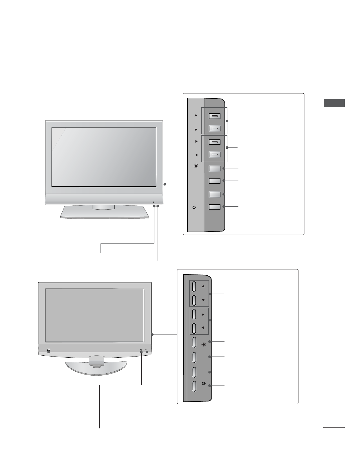
Front Panel Controls..................................................... 4
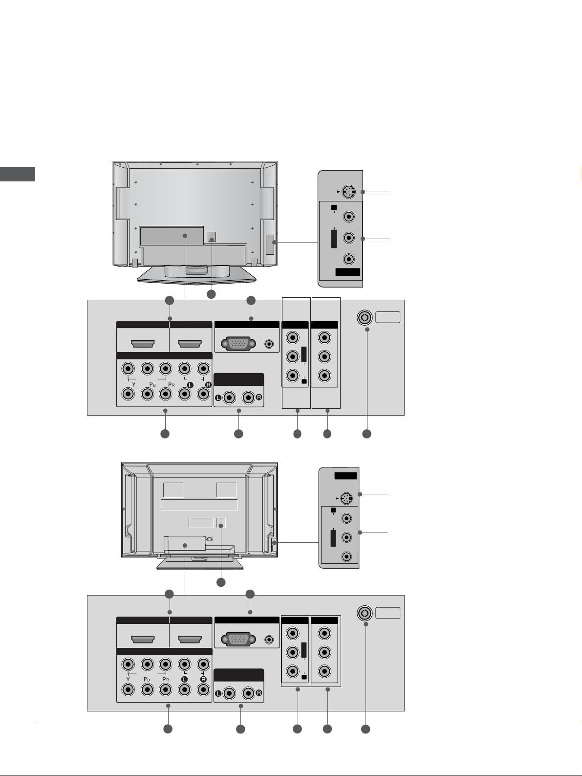
Back Panel Information ................................................ 6
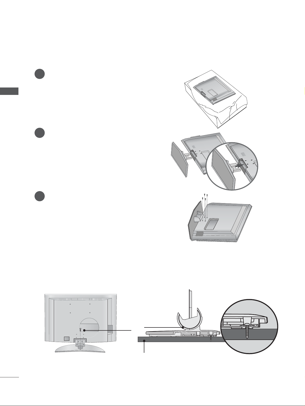
Stand Installation........................................................... 8
ATTACHING THE TV TO A DESK (Only 32LB9R*model) ........ 8
Attaching the TV to a Wall ...........................................9
Back Cover for Wire Arrangement .......................... 10
Desktop Pedestal Installation................................... 12
Wall Mount: Horizontal installation ........................ 13
Antenna Connection................................................... 14
PICTURE CONTROL
Watching PIP(Picture-in-Picture) .............................46
Picture Size (Aspect Ratio)Control.........................48
Preset Picture Settings
- Picture Mode-Preset............................................50
- Auto Colour Tone Control(Warm/Medium/Cool)
51
Manual Picture Adjustment
- Picture Mode-User Option................................52
- Colour Tone - User Option...............................53
-
Picture Improvement Technology
...................54
- Demo................................................................55
Advanced - Cinema......................................................56
Advanced - Black(Darkness) Level...........................57
Picture Reset..................................................................58
Image Sticking Minimization(ISM) Method...........59
Low-Power Picture Mode............................................60
SOUND & LANGUAGE CONTROL
Auto Volume Leveler ....................................................61
Preset Sound Settings - Sound Mode ....................62
Sound Setting Adjustment - User Mode ...............63
Balance ............................................................................64
TV Speakers On/Off Setup.......................................65
I/II
- Stereo/Dual Reception.......................................66
- NICAM Reception ................................................67
- Speaker Sound Output Selection....................67
On-Screen Menu Language Selection
...................... 68
EXTERNAL EQUIPMENT SETUP
HD Receiver Setup .......................................................15
DVD Setup..................................................................... 18
VCR Setup..................................................................... 21
Other A/V Source Setup........................................... 24
External Stereo............................................................. 25
PC Setup.........................................................................26
- Screen Setup for PC Mode ...............................28
WATCHING TV /PROGRAMME CONTROL
REMOTE CONTROL KEY FUNCTIONS.................32
Turning on the TV....................................................... 34
Programme Selection ................................................. 34
Volume Adjustment......................................................34
On Screen Menus Selection and Adjustment ......35
Auto Programme Tuning............................................ 36
Manual Programme Tuning ....................................... 37
Fine Tuning .....................................................................38
Assigning a Station Name..........................................39
Programme Edit ........................................................... 40
Favourite Programme .................................................. 41
Calling the Programme Table ................................... 42
Key lock.......................................................................... 43
Function................................................ 44
PREPARATION PICTURE CONTROL
WATCHING TV / PROGRAMME CONTROL
AACCCCEESSSSOORRIIEESS.....................................................1
2
CONTENTS
CONTENTS

3
CONTENTS
APPENDIX
Troubleshooting........................................................73
Maintenance .............................................................75
Product Specifications ............................................76
Programming the Remote Control ..................... 78
TIME SETTING
Clock Setup....................................................................69
Auto On/Off Timer Setting .......................................70
Sleep Timer Setting......................................................71
Auto Shut-off Setting...................................................72

4
PREPARATION
PREPARATION
FRONT PANEL CONTROLS
■
This is a simplified representation of the front panel. Here shown may be somewhat different from your TV.
■
If your product has a protection film attached, remove the film and then wipe the product with a polishing
cloth.
PR
VOL
OK
MENU
INPUT
Power/Standby Indicator
• illuminates red in standby mode.
• illuminates green when the set is switched on.
Remote Control Sensor
Plasma TV Models
PR
VOL
OK
MENU
INPUT
PR
VOL
OK
MENU
INPUT
PRPR
VOLVOL
OKOK
MENUMENU
INPUTINPUT
Power/Standby Indicator
• illuminates red in standby mode.
• illuminates green when the set is
switched on.
42/50PC5R*
42PC7R*
PROGRAMME Buttons
VOLUME Buttons
MENU Button
OK Button
INPUT Button
POWER Button
PR
VOL
OK
MENU
INPUT
PROGRAMME Buttons
VOLUME Buttons
MENU Button
OK Button
INPUT Button
POWER Button
PR
VOL
OK
MENU
INPUT
PR
VOL
OK
MENU
INPUT
PR
VOL
OK
MENU
INPUT
PR
VOL
OK
MENU
INPUT
Remote Control Sensor

5
PREPARATION
LCD TV Models
Remote Control Sensor
Power/Standby Indicator
• illuminates red in standby mode.
• illuminates green when the set is switched on.
PR
VOL
OK
MENU
INPUT
/I
PROGRAMME Buttons
VOLUME Buttons
OK Button
MENU Button
INPUT Button
POWER Button
26/32/37/42LC4R*
26/32/37/42LC7R*
32/42LB9R*
PR VOL
OK
MENU INPUT
/I
Remote Control
Sensor
Intelligent Eye
Adjusts picture
according to the
surrounding con-
ditions.
Power/Standby Indicator
• illuminates red in standby mode.
• illuminates green when the set is switched on.
PROGRAMME Buttons
VOLUME Buttons
OK Button
MENU Button
INPUT Button
POWER Button

6
PREPARATION
PREPARATION
BACK PANEL INFORMATION
■
This is a simplified representation of the back panel. Here shown may be somewhat different from your TV.
Plasma TV Models
HDMI INHDMI INHDMI/DVI INHDMI/DVI IN
1
1
2
2
VARIABLEARIABLE AUDIO OUTAUDIO OUT
AUDIO
(RGB/DVI)
RGB
(PC)
RGB INRGB IN
COMPONENT INCOMPONENT IN
AUDIO
VIDEO
AV IN 1V IN 1 AV OUTV OUT
L/L/MONOMONO
R
AUDIOAUDIO
VIDEO
ANTENNA
IN
HDMI INHDMI/DVI IN
1
1
2
2
VARIABLE AUDIO OUT
RGB IN
COMPONENT IN
AV IN 1 AV OUT
L/MONO
R
AUDIO
VIDEO
RS-232C IN
(CONTROL & SERVICE)
AV 1 AV 2
ANTENNA
IN
VARIABLE AUDIO OUT
VIDEO
AUDIO
COMPONENT IN
AV IN 3
L/MONO
R
AUDIO
VIDEO
HDMI/DVI IN HDMI IN
12
RGB IN
S-VIDEO
21
43 5 7
8
6
S-Video Input
Connect S-Video out from an
S-VIDEO device.
Audio/Video Input
Connect audio/video output
from an external device to
these jacks.
AV IN 2V IN 2
L/MONOMONO
R
AUDIOAUDIO
VIDEO
S-VIDEOS-VIDEO
HDMI INHDMI/DVI IN
1
1
2
2
VARIABLE
AUDIO OUT
RGB IN
COMPONENT IN
AV IN 1 AV OUT
L/MONO
R
AUDIO
VIDEO
HDMI INHDMI/DVI IN
1
1
2
2
VARIABLE
AUDIO OUT
RGB IN
COMPONENT IN
AV IN 1 AV OUT
L/MONO
R
AUDIO
VIDEO
RS-232C IN
(CONTROL & SERVICE)
AV IN 2
L/MONO
R
AUDIO
VIDEO
S-VIDEO
HDMI IN
HDMI IN
HDMI/DVI IN
HDMI/DVI IN
1
1
2
2
VARIABLE
ARIABLE
AUDIO OUT
AUDIO OUT
AUDIO
(RGB/DVI)
RGB
(PC)
RGB IN
RGB IN
COMPONENT IN
COMPONENT IN
AUDIO
VIDEO
AV IN 1
V IN 1
AV OUT
V OUT
L/
L/
MONO
MONO
R
AUDIO
AUDIO
VIDEO
ANTENNA
IN
HDMI INHDMI/DVI IN
1
1
2
2
VARIABLE AUDIO OUT
RGB IN
COMPONENT IN
AV IN 1 AV OUT
L/MONO
R
AUDIO
VIDEO
RS-232C IN
(CONTROL & SERVICE)
AV IN 2
L/MONO
R
AUDIO
VIDEO
S-VIDEO
HDMI INHDMI/DVI IN
1
1
2
2
VARIABLE AUDIO OUT
RGB IN
COMPONENT IN
AV IN 1 AV OUT
L/MONO
R
AUDIO
VIDEO
HDMI INHDMI/DVI IN
1
1
2
2
VARIABLE AUDIO OUT
RGB IN
COMPONENT IN
AV IN 1 AV OUT
L/MONO
R
AUDIO
VIDEO
RS-232C IN
(CONTROL & SERVICE)
21
4
3 5 7
8
6
S-Video Input
Connect S-Video out from an
S-VIDEO device.
Audio/Video Input
Connect audio/video output
from an external device to
these jacks.
AV IN 2V IN 2
L/L/MONOMONO
R
AUDIO
VIDEO
S-VIDEO
HDMI INHDMI/DVI IN
1
1
2
2
VARIABLE AUDIO OUT
RGB IN
COMPONENT IN
AV IN 1 AV OUT
L/MONO
R
AUDIO
VIDEO
HDMI INHDMI/DVI IN
1
1
2
2
VARIABLE AUDIO OUT
RGB IN
COMPONENT IN
AV IN 1 AV OUT
L/MONO
R
AUDIO
VIDEO
RS-232C IN
(CONTROL & SERVICE)
42/50PC5R*
42PC7R*

AV IN 3
L/MONO
R
AUDIO
VIDEO
S-VIDEO
12
VARIABLE
AUDIO OUT
RGB IN
COMPONENT IN
AUDIO
VIDEO
AV 1 AV 2
ANTENNA
IN
HDMI/DVI IN HDMI IN
HDMI Input
Connect a HDMI signal to HDMI IN.
Or DVI(VIDEO)signal to HDMI/DVI port with DVI
to HDMI cable.
RGB/Audio Input
Connect the monitor output from a PC to the
appropriate input port.
Component Input
Connect a component video/audio device to
these jacks.
Variable Audio Output
Connect an external amplifier or add a subwoofer
to your surround sound system.
Audio/Video Input (AV IN 1)
Connect audio/video output from an external
device to these jacks.
AV Output
Connect second TV or monitor to the AV OUT
socket on the set.
Antenna Input
Connect over-the-air signals to this jack.
Power Cord Socket
This TV operates on an AC power. The voltage is
indicated on the Specifications page. Never
attempt to operate the TV on DC power.
1
2
3
4
5
6
7
8
AV IN 2
L/MONO
R
AUDIO
VIDEO
S-VIDEO
HDMI INHDMI INHDMI/DVI INHDMI/DVI IN
1
1
2
2
VARIABLEARIABLE
AUDIO OUTAUDIO OUT
AUDIO
(RGB/DVI)
RGB
(PC)
RGB INRGB IN
COMPONENT INCOMPONENT IN
AUDIO
VIDEO
AV IN 1V IN 1 AV OUTV OUT
L/L/MONOMONO
R
AUDIOAUDIO
VIDEOVIDEO
ANTENNA
IN
HDMI INHDMI/DVI IN
1
1
2
2
VARIABLE
AUDIO OUT
RGB IN
COMPONENT IN
AV IN 1 AV OUT
L/MONO
R
AUDIO
VIDEO
RS-232C IN
(CONTROL & SERVICE)
21
43 5 76
S-Video Input
Connect S-Video out from an
S-VIDEO device.
Audio/Video Input
Connect audio/video output
from an external device to
these jacks.
AV IN 2V IN 2
L/L/MONOMONO
R
AUDIOAUDIO
VIDEOVIDEO
S-VIDEOS-VIDEO
HDMI INHDMI/DVI IN
1
1
2
2
VARIABLE
AUDIO OUT
RGB IN
COMPONENT IN
AV IN 1 AV OUT
L/MONO
R
AUDIO
VIDEO
HDMI INHDMI/DVI IN
1
1
2
2
VARIABLE
AUDIO OUT
RGB IN
COMPONENT IN
AV IN 1 AV OUT
L/MONO
R
AUDIO
VIDEO
RS-232C IN
(CONTROL & SERVICE)
7
PREPARATION
LCD TV Models
8

8
PREPARATION
PREPARATION
STAND INSTALLATION (Only 26, 32,37 inch LCD TV models)
1
2
3
Carefully place the product screen side down on
a cushioned surface that will protect product and
screen from damage.
Assemble the product stand with the product as
shown.
Install the 4 bolts securely, in the back of the
product in the holes provided.
ATTACHING THE TV TO A DESK (Only 32LB9R*model)
If you wish to attach the TV to a desk, it must be securely fastened to the desk using a metal screw (as shown
below). Failure to securely attach the TV may result in the TV falling; which may cause damage to the TV and
serious personal injury.
1-Screw
Stand
Desk

9
ATTACHING THE TV TO A WALL
(This feature is not available for all models.)
PREPARATION
Plasma TV models LCD TV models
2
1
■Set it up close to the wall so the product doesn’t fall over when it is pushed backwards.
■The instructions shown below is a safer way to set up the product, which is to fix it on the wall so the
product doesn’t fall over when it is pulled in the forward direction. It will prevent the product from
falling for-ward and hurting people. It will also prevent the product from damage caused by fall. Please
make sure that children don’t climb on or hang from the product.
NOTE
!
GGWhen moving the product to another place undo the ropes first.
GGUse a product holder or a cabinet that is big and strong enough for the size and weight of the product.
GGTo use the product safely make sure that the height of the bracket that is mounted on the wall is same
as that of the product.
2
3
1
1
2
Use the eye-bolts or TV brackets/bolts to fix the product to the wall as shown in the picture.
(If your product has the bolts in the eye-bolts position before inserting the eye-bolts, loosen the bolts.)
* Insert the eye-bolts or TV brackets/bolts and tighten them securely in the upper holes.
Secure the wall brackets with the bolts (not provided as parts of the product, must purchase separately) on
the wall. Match the height of the bracket that is mounted on the wall.
3Use a sturdy rope (not provided as parts of the product, must purchase separately) to tie the
product. It is safer to tie the rope so it becomes horizontal between the wall and the product.

10
PREPARATION
PREPARATION
BACK COVER FOR WIRE ARRANGEMENT
Plasma TV models
■These models have two cable arrangement methods according to the stand type.
Connect the cables as necessary.
To connect an additional equipment, see the
EExxtteerrnnaalleeqquuiippmmeennttCCoonnnneeccttiioonnsssection.
Reinstall the CCAABBLLEEMMAANNAAGGEEMMEENNTTas shown.
2
1
3
CABLE MANAGEMENT
Hold the CCAABBLLEEMMAANNAAGGEEMMEENNTTwith hands and push it as shown.
Stand type 1
Stand type 2
Arrange the cables as shown picture.

11
PREPARATION
LCD TV models
Connect the cables as necessary.
To connect an additional equip-
ment, see the EExxtteerrnnaall
eeqquuiippmmeennttCCoonnnneeccttiioonnss
section.
1
Install the CCAABBLLEEMMAANN--
AAGGEEMMEENNTTas shown.
2
Bundle the cables using the
supplied twister holder.
(
This feature is not available
for all models.)
3
Hold the CCAABBLLEEMMAANNAAGGEEMMEENNTTwith both hands and pull it upward.
NOTE
!
GGDo not hold the CABLE MANAGEMENT when moving the product.
- If the product is dropped, you may be injured or the product may be broken.
How to remove the cable management
CABLE MANAGEMENT
TWIST HOLDER
or
or
or
or
(Insert it as pushing the loops on the
both sides of the cable management.)
(Pull it out as holding the loops on the both
sides of the cable management.)

12
■The TV can be installed in various ways such as on a wall, or on a desktop etc.
■The TV is designed to be mounted horizontally.
PREPARATION
PREPARATION
DESKTOP PEDESTAL INSTALLATION
For proper ventilation, allow a clearance of 4inches on each side from the wall.
4 inches
4 inches
4 inches 4 inches
Power Supply
Short-circuit Breaker
GROUNDING
Ensure that you connect the earth ground wire to prevent possible electric shock. If grounding methods
are not possible, have a qualified electrician install a separate circuit breaker.
Do not try to ground the unit by connecting it to telephone wires, lightening rods, or gas pipes.

13
PREPARATION
WALL MOUNT: HORIZONTAL INSTALLATION
For proper ventilation, allow a clearance of 4" on each side and from the wall. Detailed installation instruc-
tions are available from your dealer, see the optional Tilt Wall Mounting Bracket Installation and Setup Guide.
4 inches
4 inches
4 inches
4 inches
4 inches
<<OOnnllyy4422PPCC77RR*>>
Remove two screws of the backside of the set before
installing the wall mounting bracket.

14
PREPARATION
AV IN 3
L/MONO
R
AUDIO
VIDEO
S-VIDEO
12
VARIABLE
AUDIO OUT
RGB IN
COMPONENT IN
AUDIO
VIDEO
AV 1 AV 2
ANTENNA
IN
HDMI/DVI IN HDMI IN
AV 1 AV 2
ANTENNA
IN
VARIABLE
AUDIO OUT
VIDEO
AUDIO
COMPONENT IN
AV IN 3
L/MONO
R
AUDIO
VIDEO
HDMI/DVI IN HDMI IN
12
RGB IN
S-VIDEO
AV IN 2
L/MONO
R
AUDIO
VIDEO
S-VIDEO
HDMI INHDMI/DVI IN
1
1
2
2
VARIABLE
AUDIO OUT
RGB IN
COMPONENT IN
AV IN 1 AV OUT
L/MONO
R
AUDIO
VIDEO
ANTENNA
IN
HDMI INHDMI/DVI IN
1
1
2
2
VARIABLE
AUDIO OUT
RGB IN
COMPONENT IN
AV IN 1 AV OUT
L/MONO
R
AUDIO
VIDEO
RS-232C IN
(CONTROL & SERVICE)
AV IN 2
L/MONO
R
AUDIO
VIDEO
S-VIDEO
HDMI INHDMI/DVI IN
1
1
2
2
VARIABLE
AUDIO OUT
RGB IN
COMPONENT IN
AV IN 1 AV OUT
L/MONO
R
AUDIO
VIDEO
ANTENNA
IN
HDMI INHDMI/DVI IN
1
1
2
2
VARIABLE
AUDIO OUT
RGB IN
COMPONENT IN
AV IN 1 AV OUT
L/MONO
R
AUDIO
VIDEO
RS-232C IN
(CONTROL & SERVICE)
PREPARATION
ANTENNA CONNECTION
■For optimum picture quality, adjust antenna direction.
■An antenna cable and converter are not supplied.
Multi-family Dwellings/Apartments
(Connect to wall antenna socket)
Single-family Dwellings /Houses
(Connect to wall jack for outdoor antenna)
Outdoor
Antenna
Wall
Antenna
Socket
RF Coaxial Wire (75 ohm)
Antenna
UHF
Signal
Amplifier
VHF
■In poor signal areas,to get better picture quality, install a signal amplifier to the antenna as shown above.
■If signal needs to be split for two TVs,use an antenna signal splitter for connection.
■To prevent the equipment damage, never plug in any power cords until you have finished connecting all equipment.

15
EXTERNAL EQUIPMENT SETUP
HDMI INHDMI DVI IN
1
2
COMPONENT INCOMPONENT IN
AUDIO
VIDEO
HDMI INHDMI DVI IN RGB IN
HDMI/DVI IN
1
HDMI INHDMI DVI IN HDMI INHDMI/DVI IN
12
1 2
EXTERNAL EQUIPMENT SETUP
HD RECEIVER SETUP
When connecting with a component cable
Connect the video outputs (Y, PB, PR)of the digital set
top box to the CCOOMMPPOONNEENNTTIINNVVIIDDEEOOjacks on the
set.
Connect the audio output of the digital set-top box to
the CCOOMMPPOONNEENNTTIINNAAUUDDIIOOjacks on the set.
Turn on the digital set-top box.
(Refer to the owner’s manual for the digital set-top box.)
Select Component1 input source with using the
IINNPPUUTTbutton on the remote control.
If connected to CCOOMMPPOONNEENNTTIINN22, select
Component2 input source.
2
3
4
1
Signal
480i/576i
480p/576p
720p/1080i
108 0 p
Component
Yes
Yes
Yes
No
HDMI1/2
No
Yes
Yes
Yes
■To prevent the equipment damage, never plug in any power cords until you have finished connecting all equipment.
■This part of EXTERNAL EQUIPMENT SETUP mainly use pictures for the LCD TV models.
(except VGA Models)

HDMI INHDMI DVI IN
1
2
COMPONENT IN
HDMI INHDMI DVI IN RGB IN
HDMI/DVI IN
1
HDMI INHDMI DVI IN HDMI INHDMI INHDMI/DVI INHDMI/DVI IN
1 2
1
16
EXTERNAL EQUIPMENT SETUP
When connecting with a HDMI cable
Connect the HDMI output of the digital set-top box to
the HHDDMMII//DDVVIIIINN11or HHDDMMIIIINN22jack on the set.
Select HDMI1 or HDMI2 input source with using the
IINNPPUUTTbutton on the remote control.
Turn on the digital set-top box.
(Refer to the owner’s manual for the digital set-top box.)
2
3
1
GGTV can receive the video and audio signal simultaneously with using a HDMI cable.
GGIf the digital set-top box supports Auto HDMI function, the output resolution of the source device will
be automatically set to 1280x720p.
GGIf the digital set-top box player does not support Auto HDMI, you need to set the output resolution
appropriately.
To get the best picture quality, adjust the output resolution of the source device to 1280x720p.
NOTE
!

HDMI INHDMI DVI IN
1
2
COMPONENT IN
AV IN 1AV IN 1 AV OUTAV OUT
AUDIO
(RGB/DVI)
RGB
(PC)
HDMI INHDMI DVI IN
AUDIO
(RGB/DVI)
RGB(PC)
RGB IN
HDMI/DVI IN
1
HDMI INHDMI DVI IN HDMI INHDMI/DVI IN
12
L/MONO
12
17
EXTERNAL EQUIPMENT SETUP
Connect the DVI output of the digital set-top box to the HHDDMMII//DDVVIIIINN11jack on the set.
Connect the audio output of the digital set-top box to the AAUUDDIIOO((RRGGBB//DDVVII))jack on the set.
Turn on the digital set-top box. (Refer to the owner’s manual for the digital set-top box.)
Select HDMI1 input source with using the IINNPPUUTTbutton on the remote control.
2
3
4
1
When connecting with a HDMI to DVI cable

HDMI INHDMI DVI IN
HDMI INHDMI DVI IN
RG
HDMI INHDMI DVI IN
AV IN 2
L/MONO
R
AUDIO
VIDEO
S-VIDEO
1
2
COMPONENT INCOMPONENT IN
AUDIO
VIDEO
HDMI INHDMI/DVI IN
12
AV IN 1
L/MONO
R
AUDIO
VIDEO
1 2
18
DVD SETUP
EXTERNAL EQUIPMENT SETUP
When connecting with a component cable
Component Input ports
To get better picture quality, connect a DVD player to the component input ports as shown below.
Component ports on the TV
YPBPR
Video output ports
on DVD player
Y
Y
Y
Y
PB
B-Y
Cb
Pb
PR
R-Y
Cr
Pr
Connect the video outputs (Y, PB, PR)of the DVD to the
CCOOMMPPOONNEENNTTIINNVVIIDDEEOOjacks on the set.
Connect the audio outputs of the DVD to the CCOOMMPPOO--
NNEENNTTIINNAAUUDDIIOOjacks on the set.
Tur n on the DVD player, insert a DVD.
Select Component input source with using the IINNPPUUTT
button on the remote control.
If connected to CCOOMMPPOONNEENNTTIINN22, select Component2
input source.
Refer to the DVD player's manual for operating instructions.
2
3
4
5
1
This manual suits for next models
61
Table of contents
Other LG LCD TV manuals