LG 32LC4 Series User manual

LCD TV PLASMA TV
OWNER’S MANUAL
LCD TV MODELS
26LC4*
32LC4*
37LC4*
42LC4*
PLASMA TV MODELS
42PC5*
50PC5*
Please read this manual carefully before operating your set.
Retain it for future reference.
Record model number and serial number of the set.
See the label attached on the back cover and quote
this information to your dealer when you require service.
26LC5*
32LC5*
37LC5*
42LC5*
ENGLISH


1
ACCESSORIES
Ensure that the following accessories are included with your TV. If an accessory is missing, please contact the
dealer where you purchased the product.
Owner’s Manual Batteries
OK
INPUT
TVTV
PIP PR- PIP PR+
PIPINPUT
DVD
ARC
EXIT
VOL
TIME
REVEAL
INDEX
Q.VIEW
PR
SLEEP
LIST
I/II
MENU
PIP SIZE
POSTION
VCR
POWER
123
456
789
*
FAV
?
0
TEXT
INPUT
MUTE
Remote Control Power Cord
Cable Management
2- TV Brackets
2- all Brackets
2-bolts
Twister Holder
Arrange the wires
with the twister
holder.
LLCCDD TTVV mmooddeellss
PPllaassmmaa TTVV mmooddeellss
4-bolts for stand assembly
Refer to p. 8
66””,, 33””,, 3377”” oonnllyy
2- all brackets 2-eye-bolts
ACCESSORIES
Polishing Cloth
Polish the screen with the cloth
This feature is not available
for all models.
*Slightly wipe stained spot on the exterior only with the cleans-
ing cloths for the product exterior if there is stain or fingerprint on
surface of the exterior.
Do not wipe roughly when removing stain. Please be cautious of
that excessive power may cause scratch or discoloration.
Owner's
Manual
Owner's manual

2
CONTENTS
PREPARATION
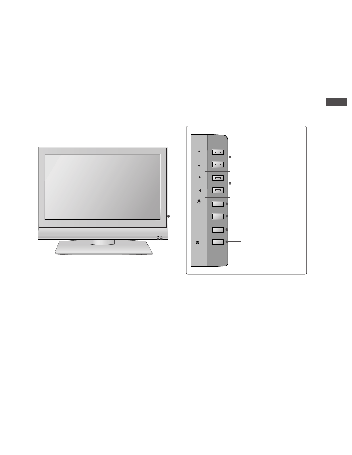
Front Panel Controls....................................................... 4
Back Panel Information .................................................. 6
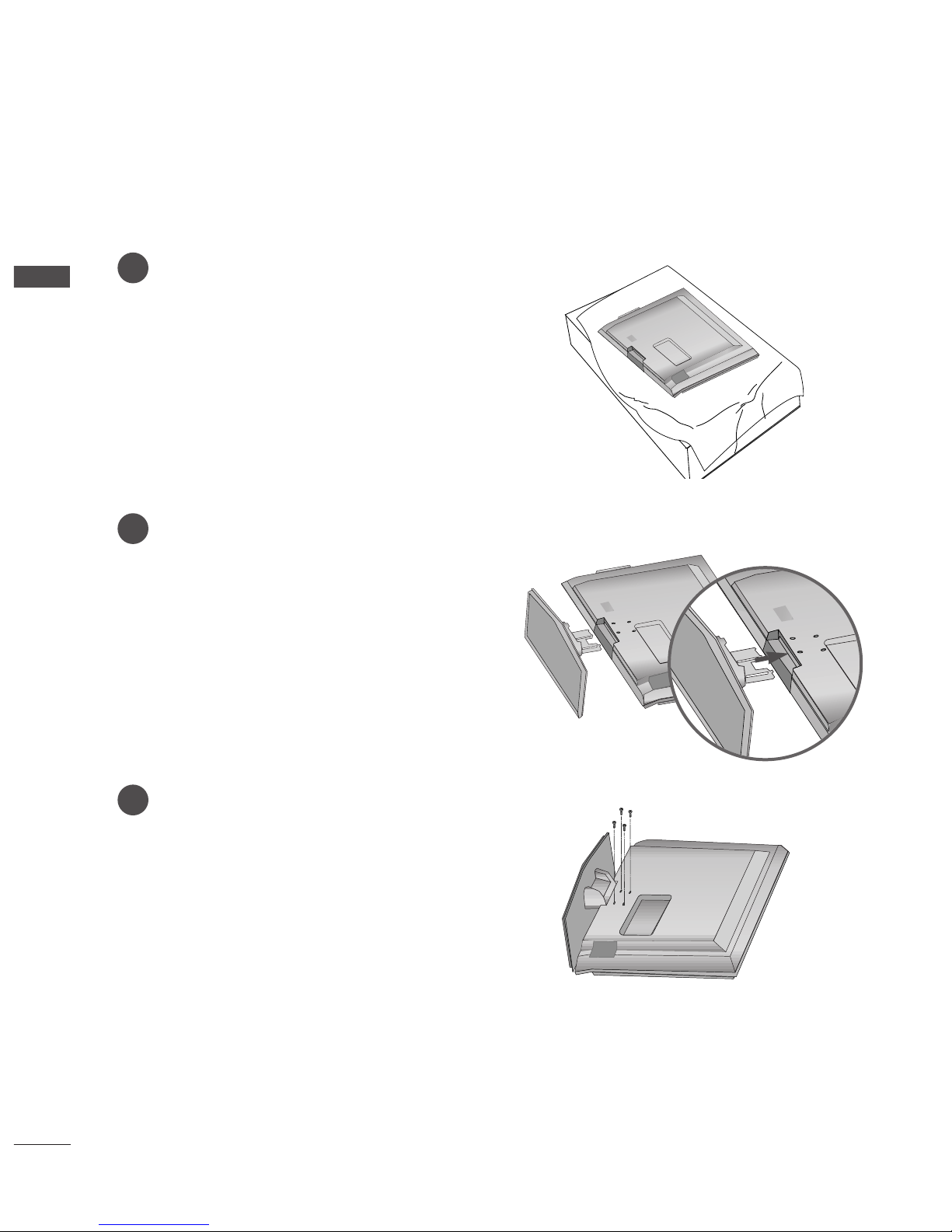
Stand Installation............................................................. 8
Attaching the TV to a Wall .............................................
Back Cover for Wire Arrangement............................ 10
Desktop Pedestal Installation..................................... 12
Wall Mount: Horizontal installation.......................... 13
Antenna Connection .................................................... 14
PICTURE CONTROL
Picture Size (Aspect Ratio)Control...........................46
Preset Picture Settings
- Picture Mode-Preset .............................................48
- Auto Colour Tone Control(Warm/Medium/Cool)
..4
Manual Picture Adjustment
- Picture Mode-User Option .................................50
- Colour Tone - User Option .................................51
-
Picture Improvement Technology
.....................52
Demo...................................................................53
Advanced - Cinema........................................................54
Advanced - Black(Darkness) Level.............................55
Picture Reset....................................................................56
Image Sticking Minimization(ISM) Method ............57
Low-Power Picture Mode..............................................58
SOUND & LANGUAGE CONTROL
Auto Volume Leveler ......................................................5
Preset Sound Settings - Sound Mode......................60
Sound Setting Adjustment - User Mode .................61
Balance..............................................................................62
TV Speakers On/Off Setup.........................................63
I/II
- Stereo/Dual Reception.........................................64
- NICAM Reception..................................................65
- Speaker Sound Output Selection .....................65
On-Screen Menu Language /Country Selection
...... 66
EXTERNAL EQUIPMENT SETUP
HD Receiver Setup .........................................................15
DVD Setup....................................................................... 18
VCR Setup....................................................................... 21
Other A/V Source Setup ............................................ 24
External Stereo............................................................... 25
PC Setup...........................................................................26
- Screen Setup for PC Mode .................................28
WATCHING TV /PROGRAMME CONTROL
Remote Control Key Functions...................................32
Turning on the TV......................................................... 34
Programme Selection ................................................... 34
Volume Adjustment........................................................34
On Screen Menu Selection and Adjustment ..........35
Auto Programme Tuning.............................................. 36
Manual Programme Tuning ......................................... 37
Fine Tuning .......................................................................38
Assigning a Station Name............................................3
Programme Edit ............................................................. 40
Favourite Programme .................................................... 41
Calling the Programme Table ..................................... 42
Key lock ........................................................................... 43
................................................................... 44
PREPARATION PICTURE CONTROL
WATCHING TV / PROGRAMME CONTROL
AACCCCEESSSSOORRIIEESS......................................................1
CONTENTS

3
CONTENTS
APPENDIX
roubleshooting..............................................................74
Maintenance ...................................................................76
Product Specifications ..................................................77
Programming the Remote Control .......................... 79
TIME SETTING
Clock Setup......................................................................67
Auto On/Off imer Setting .........................................68
Sleep imer Setting .......................................................69
Auto Shut-off Setting ....................................................70
TELETEXT
Switch On/Off.................................................................71
SIMPLE ext .....................................................................71
OP ext...........................................................................72
FAS EX ...........................................................................72
Special eletext Functions............................................73

4
PREPARATION
FRONT PANEL CONTROLS
PREPARATION
■
This is a simplified representation of the front panel. Here shown may be somewhat different from your TV.
■
If your product has a protection film attached, remove the film and then wipe the product with a polishing
cloth.
Plasma TV Models
PR
VOL
OK
MENU
INPUT
PROGRAMME
Buttons
VOLUME
Buttons
MENU
Button
OK
Button
INPUT
Button
POWER
Button
PR
VOL
OK
MENU
INPUT
PR
VOL
OK
MENU
INPUT
Power/Stand y Indicator
• illuminates red in standby mode.
• illuminates green when the set is switched on.
Remote Control Sensor

5
PREPARATION
LCD TV Models
R
Remote Control Sensor
Power/Standby Indicator
• illuminates red in standby mode.
• illuminates green when the set is switched on.
PR
VOL
OK
MENU
INPUT
/I
PROGRAMME Buttons
VOLUME Buttons
OK Button
MENU Button
INPUT Button
POWER Button

6
PREPARATION
BACK PANEL INFORMATION
PREPARATION
■
his is a simplified representation of the back panel. Here shown may be somewhat different from your V.
Plasma TV Models
HDMI Input
Connect a HDMI signal to HDMI IN.
Or DVI(VIDEO)signal to HDMI/DVI port with DVI
to HDMI cable.
RGB/Audio Input
Connect the monitor output from a PC/D V(only
Audio) to the appropriate input port.
Component Input
Connect a component video/audio device to
these jacks.
Variable Audio Output
Connect an external amplifier or add a subwoofer
to your surround sound system.
Euro Scart Socket (AV1/AV2)
Connect scart socket input or output from an
external device to these jacks.
Antenna Input
Connect over-the-air signals to this jack.
Power Cord Socket
his V operates on an AC power. he voltage is
indicated on the Specifications page. Never
attempt to operate the V on DC power.
1
2
3
4
5
6
7
AV 1 AV 2
ANTENNA
IN
VARIABLE AUDIO OUT
VIDEO
AUDIO
COMPONENT IN
AV IN 3
L/MONO
R
AUDIO
VIDEO
HDMI/DVI IN HDMI IN
12
RGB IN
S-VIDEO
AUDIO
(RGB/DVI)
RGB
(PC)
AV 1 AV 2
ANTENNA
IN
VARIABLE
ARIABLE
AUDIO OUT
UDIO OUT
VIDEO
VIDEO
AUDIO
COMPONENT IN
COMPONENT IN
AV IN 3
L/MONO
R
AUDIO
VIDEO
HDMI/DVI IN HDMI IN
1 2
RGB IN
S-VIDEO
21
43 5 6 7
S-Video Input
Connect S-Video out from an
S-VIDEO device.
Audio/Video Input
Connect audio/video output
from an external device to
these jacks.
AV 1 AV 2
ANTENNA
IN
VARIABLE AUDIO OUT
VIDEO
AUDIO
COMPONENT IN
AV IN 3V IN 3
L/L/MONOMONO
R
AUDIOAUDIO
VIDEOVIDEO
HDMI/DVI IN HDMI IN
12
RGB IN
S-VIDEOS-VIDEO
AV 1 AV 2
ANTENNA
IN
AC IN
VARIABLE
AUDIO OUT
VIDEO
AUDIO
COMPONENT IN
AV IN 3
L/MONO
R
AUDIO
VIDEO
HDMI/DVI IN HDMI IN
12
RGB IN
S-VIDEO

7
PREPARATION
HDMI Input
Connect a HDMI signal to HDMI IN.
Or DVI(VIDEO)signal to HDMI/DVI port with DVI
to HDMI cable.
RGB/Audio Input
Connect the monitor output from a PC/D V(only
Audio) to the appropriate input port.
Component Input
Connect a component video/audio device to
these jacks.
Variable Audio Output
Connect an external amplifier or add a subwoofer
to your surround sound system.
Euro Scart Socket (AV1/AV2)
Connect scart socket input or output from an
external device to these jacks.
Antenna Input
Connect over-the-air signals to this jack.
Power Cord Socket
his V operates on an AC power. he voltage is
indicated on the Specifications page. Never
attempt to operate the V on DC power.
1
2
3
4
5
6
7
LCD TV Models
AV IN 3
L/MONO
R
AUDIO
VIDEO
S-VIDEO
12
VARIABLE
AUDIO OUT
RGB IN
COMPONENT IN
AUDIO
VIDEO
AV 1 AV 2
ANTENNA
IN
HDMI/DVI IN HDMI IN
AV IN 3
L/MONO
R
AUDIO
VIDEO
S-VIDEO
1 2
VARIABLE
ARIABLE
AUDIO OUT
AUDIO OUT
RGB
(PC)
RGB IN
RGB IN
COMPONENT IN
COMPONENT IN
AUDIO
AUDIO
VIDEO
VIDEO
AV 1
V 1
AV 2
V 2
ANTENNA
IN
AUDIO
(RGB/DVI)
HDMI/DVI IN HDMI IN
AC IN
AV IN 3
L/MONO
R
AUDIO
VIDEO
S-VIDEO
12
VARIABLE
AUDIO OUT
RGB IN
COMPONENT IN
AUDIO
VIDEO
AV 1 AV 2
ANTENNA
IN
HDMI/DVI IN HDMI IN
AC IN
AV IN 3
L/MONO
R
AUDIO
VIDEO
S-VIDEO
12
VARIABLE
AUDIO OUT
RGB IN
COMPONENT IN
AUDIO
VIDEO
AV 1 AV 2
ANTENNA
IN
HDMI/DVI IN HDMI IN
21
43 5 6
7
S-Video Input
Connect S-Video out from an S-
VIDEO device.
Audio/Video Input
Connect audio/video output from
an external device to these jacks.
AV IN 3
L/MONO
R
AUDIOAUDIO
VIDEOVIDEO
S-VIDEOS-VIDEO
12
VARIABLE
AUDIO OUT
RGB IN
COMPONENT IN
AUDIO
VIDEO
AV 1 AV 2
ANTENNA
IN
HDMI/DVI IN HDMI IN

8
PREPARATION
STAND INSTALLATION (Only 26, 32, 37 inch LCD TV models)
PREPARATION
1
2
3
Carefully place the product screen side down on
a cushioned surface that will protect product and
screen from damage.
Assemble the product stand with the product as
shown.
Install the 4 bolts securely, in the back of the
product in the holes provided.

9
PREPARATION
ATTACHING THE TV TO A WALL
Plasma TV models LCD TV models
2
1
■Set it up close to the wall so the product doesn’t fall over when it is pushed backwards
■The instructions shown below is a safer way to set up the product, which is to fix it on the wall so the
product doesn’t fall over when it is pulled in the forward direction It will prevent the product from
falling for-ward and hurting people It will also prevent the product from damage caused by fall Please
make sure that children don’t climb on or hang from the product
NOTE
!
GGWhen moving the product to another place undo the ropes first.
GGUse a product holder or a cabinet that is big and strong enough for the size and weight of the product.
GGo use the product safely make sure that the height of the bracket that is mounted on the wall is same as
that of the product.
2
3
1
1
2
Use the eye-bolts or V brackets/bolts to fix the product to the wall as shown in the picture.
(If your product has the bolts in the eye-bolts position before inserting the eye-bolts, loosen the bolts.)
* Insert the eye-bolts or V brackets/bolts and tighten them securely in the upper holes.
Secure the wall brackets with the bolts (not provided as parts of the product, must purchase separately) on
the wall. Match the height of the bracket that is mounted on the wall.
3Use a sturdy rope (not provided as parts of the product, must purchase separately) to tie the
product. It is safer to tie the rope so it becomes horizontal between the wall and the product.

10
PREPARATION
BACK COVER FOR WIRE ARRANGEMENT
PREPARATION
Plasma TV models
Connect the cables as necessary.
To connect an additional equipment, see the EExxtteerrnnaall eeqquuiippmmeennttSSeettuupp section.
Reinstall the CCAABBLLEE MMAAAAGGEEMMEETTas shown.
2
1
3
CABLE MANAGEMENT
Hold the CCAABBLLEE MMAAAAGGEEMMEETT with hands and push it as shown.

11
PREPARATION
LCD TV models
Connect the cables as necessary.
To connect an additional equipment, see the
EExxtteerrnnaall eeqquuiippmmeennttSSeettuuppsection.
1
Install the CCAABBLLEE MMAAAAGGEEMMEETTas shown.
2
Bundle the cables using the supplied twister
holder.
3
Hold the CCAABBLLEE MMAAAAGGEEMMEETTwith both
hands and pull it upward.
NOTE
!
GGDo not hold the CCAABBLLEE MMAAAAGGEEMMEETT when moving the product.
- If the product is dropped, you may be injured or the product may be broken.
How to remove the cable ma ageme t
CABLE MANAGEMENT

12
PREPARATION
■The TV can be installed in various ways such as on a wall, or on a desktop etc
■The TV is designed to be mounted horizontally
PREPARATION
DESKTOP PEDESTAL INSTALLATION
For proper ventilation, allow a clearance of 4inches on each side from the wall
4 inches
4 inches
4 inches 4 inches
Power Supply
Short-circuit Breaker
GROUNDING
Ensure that you connect the earth ground wire to prevent possible electric shock. If grounding methods
are not possible, have a qualified electrician install a separate circuit breaker.
Do not try to ground the unit by connecting it to telephone wires, lightening rods, or gas pipes.

13
PREPARATION
WALL MOUNT: HORIZONTAL INSTALLATION
For proper ventilation, allow a clearance of 4" on each side and from the wall. Detailed installation instruc-
tions are available from your dealer, see the optional ilt Wall Mounting Bracket Installation and Setup Guide.
4 inches
4 inches
4 inches
4 inches
4 inches

14
PREPARATION
AV IN 3
L/ MONO
R
AUDIO
VIDEO
S-VIDEO
12
VARIABLE
AUDIO OUT
RGB IN
COMPONENT IN
AUDIO
VIDEO
AV 1 AV 2
ANTENNA
IN
HDMI/DVI IN HDMI IN
AV 1 AV 2
ANTENNA
IN
VARIABLE
AUDIO OUT
VIDEO
AUDIO
COMPONENT IN
AV IN 3
L/ MONO
R
AUDIO
VIDEO
HDMI/DVI IN HDMI IN
12
RGB IN
S-VIDEO
AV IN 3
L/MONO
R
AUDIO
VIDEO
S-VIDEO
12
VARIABLE
AUDIO OUT
RGB IN
COMPONENT IN
AUDIO
VIDEO
AV 1 AV 2
ANTENNA
IN
HDMI/DVI IN HDMI IN
AV IN 3
L/MONO
R
AUDIO
VIDEO
S-VIDEO
12
VARIABLE
AUDIO OUT
RGB IN
COMPONENT IN
AUDIO
VIDEO
AV 1 AV 2
ANTENNA
IN
HDMI/DVI IN HDMI IN
PREPARATION
ANTENNA CONNECTION
■For optimum picture quality, adjust antenna direction.
■An antenna cable and converter are not supplied.
Multi-family Dwellings/Apartments
(Connect to wall antenna socket)
Single-family Dwellings /Houses
(Connect to wall ack for outdoor antenna)
Outdoor
Antenna
Wall
Antenna
Socket
RF Coaxial Wire (75 ohm)
UHF
Signal
Amplifier
VHF
■In poor signal areas,to get better picture quality, install a signal amplifier to the antenna as shown above.
■If signal needs to be split for two TVs,use an antenna signal splitter for connection.
■To prevent the equipment damage, never plug in an power cords until ou have finished connecting all equipment.
Antenna

15
EXTERNAL EQUIPMENT SETUP
HD RECEIVER SETUP
1
12
When connecting with a component cable
Connect the video outputs (Y, PB, PR)of the digital set
top box to the CCOOMMPPOONNEENN IINN VVIIDDEEOOjacks on the
set.
Connect the audio output of the digital set-top box to
the CCOOMMPPOONNEENN IINN AAUUDDIIOOjacks on the set.
urn on the digital set-top box.
(Refer to the owner’s manual for the digital set-top box.)
Select Component input source with using the
IINNPPUU button on the remote control.
2
3
4
1
1 2
■To prevent the eq ipment damage, never pl g in any power cords ntil yo have finished connecting all eq ipment.
■This part of EXTERNAL EQUIPMENT SETUP mainly se pict res for the LCD TV models.
Signal
480i/576i
480p/576p
720p/1080i
1080 p
Component
Yes
Yes
Yes
No
HDMI1/2
No
Yes
Yes
Yes (except VGA Models)

16
EXTERNAL EQUIPMENT SETUP
1
1 2
hen connecting with a HDMI cable
Connect the HDMI output of the digital set-top box to
the HHDDMMII//DDVVII IINN 11 or HHDDMMII IINN 22 jack on the set.
Select HDMI1 or HDMI2 input source with using the
IINNPPUUbutton on the remote control.
urn on the digital set-top box.
(Refer to the owner’s manual for the digital set-top box.)
2
3
1
GGV can receive the video and audio signal simultaneously with using a HDMI cable.
GGIf the digital set-top box supports Auto HDMI function, the output resolution of the source device will
be automatically set to 1280x720p.
GGIf the digital set-top box player does not support Auto HDMI, you need to set the output resolution
appropriately.
o get the best picture quality, adjust the output resolution of the source device to 1280x720p.
NOTE
!
1

17
EXTERNAL EQUIPMENT SETUP
1
12
12
Connect the DVI output of the digital set-top box to the HHDDMMII//DDVVII IINN 11 jack on the set.
Connect the audio output of the digital set-top box to the AAUUDDIIOO((RRGGBB//DDVVII)) jack on the set.
urn on the digital set-top box. (Refer to the owner’s manual for the digital set-top box.)
Select HDMI1 input source with using the IINNPPUUbutton on the remote control.
2
3
4
1
hen connecting with a HDMI to DVI cable

18
EXTERNAL EQUIPMENT SETUP
DVD SETUP
EXTERNAL EQUIPMENT SETUP
hen connecting with a component cable
AV IN 3
L/MONO
R
AUDIO
VIDEO
S-VIDEO
12
12
Component Input ports
To get better picture quality, connect a DVD player to the component input ports as shown below
Component ports on the V
YPBPR
Video output ports
on DVD player
Y
Y
Y
Y
PB
B-Y
Cb
Pb
PR
R-Y
Cr
Pr
Connect the video outputs (Y, PB, PR)of the DVD to the
CCOOMMPPOONNEENN IINN VVIIDDEEOOjacks on the set.
Connect the audio outputs of the DVD to the CCOOMMPPOO--
NNEENN IINN AAUUDDIIOOjacks on the set.
urn on the DVD player, insert a DVD.
Select Component input source with using the IINNPPUU
button on the remote control.
Refer to the DVD player's manual for operating instructions.
2
3
4
5
1
1 2
This manual suits for next models
28
Table of contents
Other LG LCD TV manuals