CONTENTS
4
CONTENTS
WARNING / CAUTION
. . . . . . . . . . . . . . . . . . . . . . . . . . . . 1
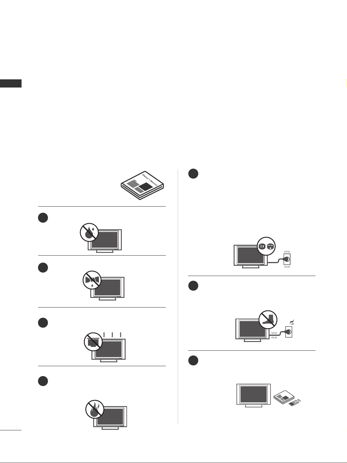
SAFETY INSTRUCTIONS
. . . . . . . . . . . . . . . . . . . . . . . . . . 2
INTRODUCTION
. . . . . . . . . . . . . . . . . . . . . . . . . . . . . . . . . . . . . . . . 6
Feature of this TV . . . . . . . . . . . . . . . . . . . . . . . . . . . . . . . . . . . . . . . . . . . . . 6
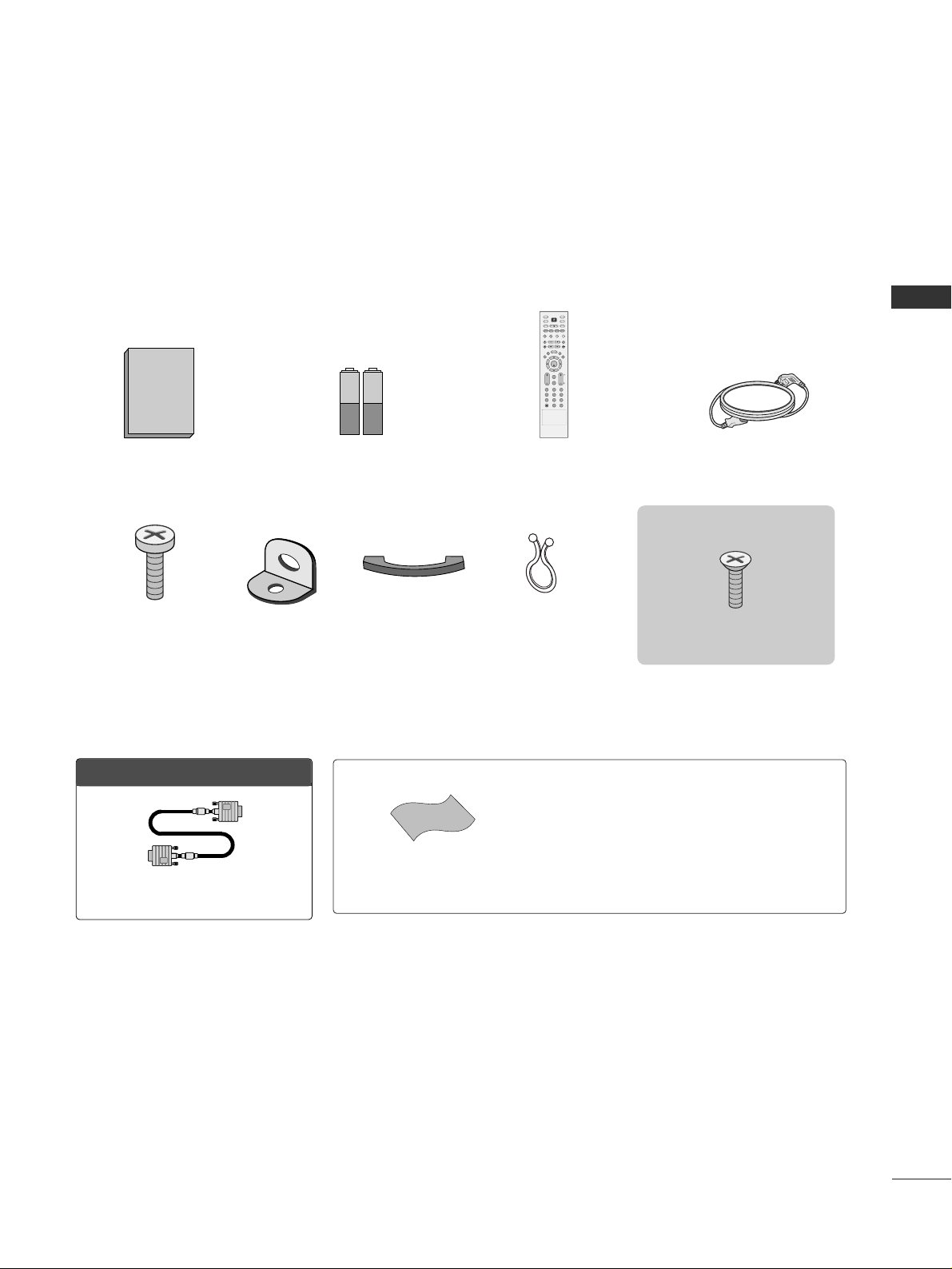
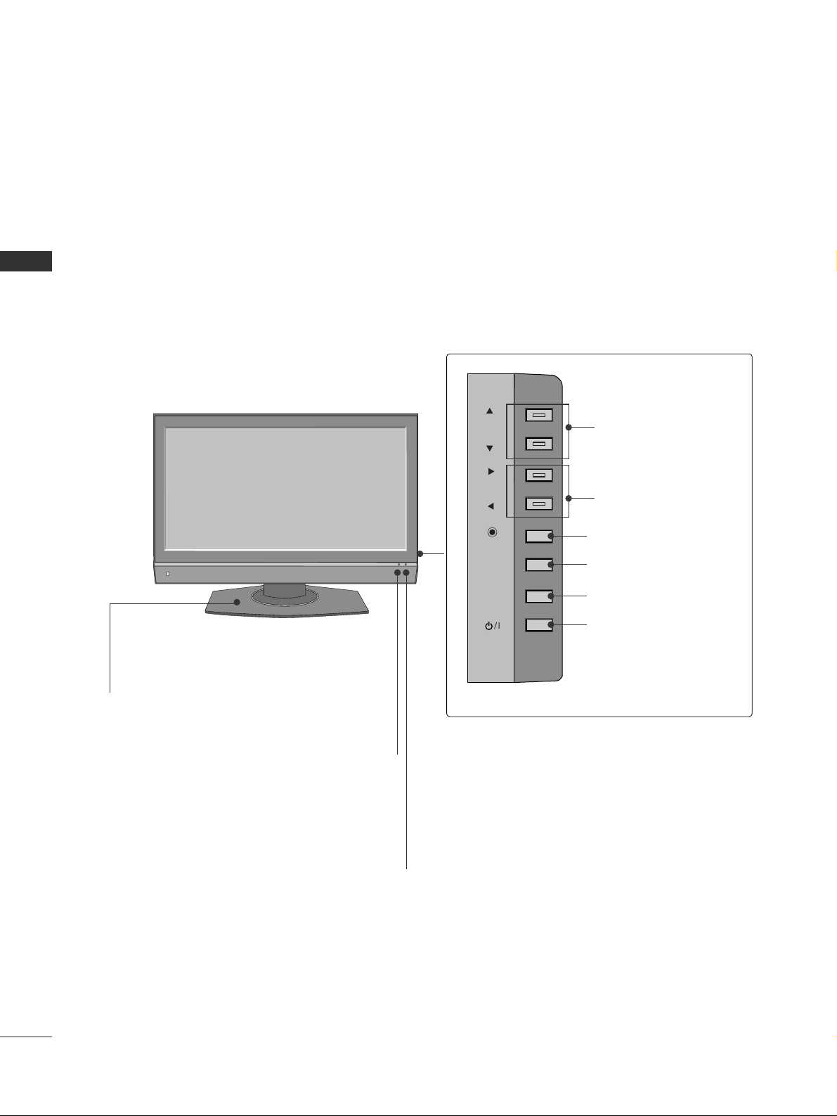
PREPARATION
Accessories . . . . . . . . . . . . . . . . . . . . . . . . . . . . . . . . . . . . . . . . . . . . . . . . . . . . . . 7
Front Panel Information . . . . . . . . . . . . . . . . . . . . . . . . . . . . . . . . . . . . . 8
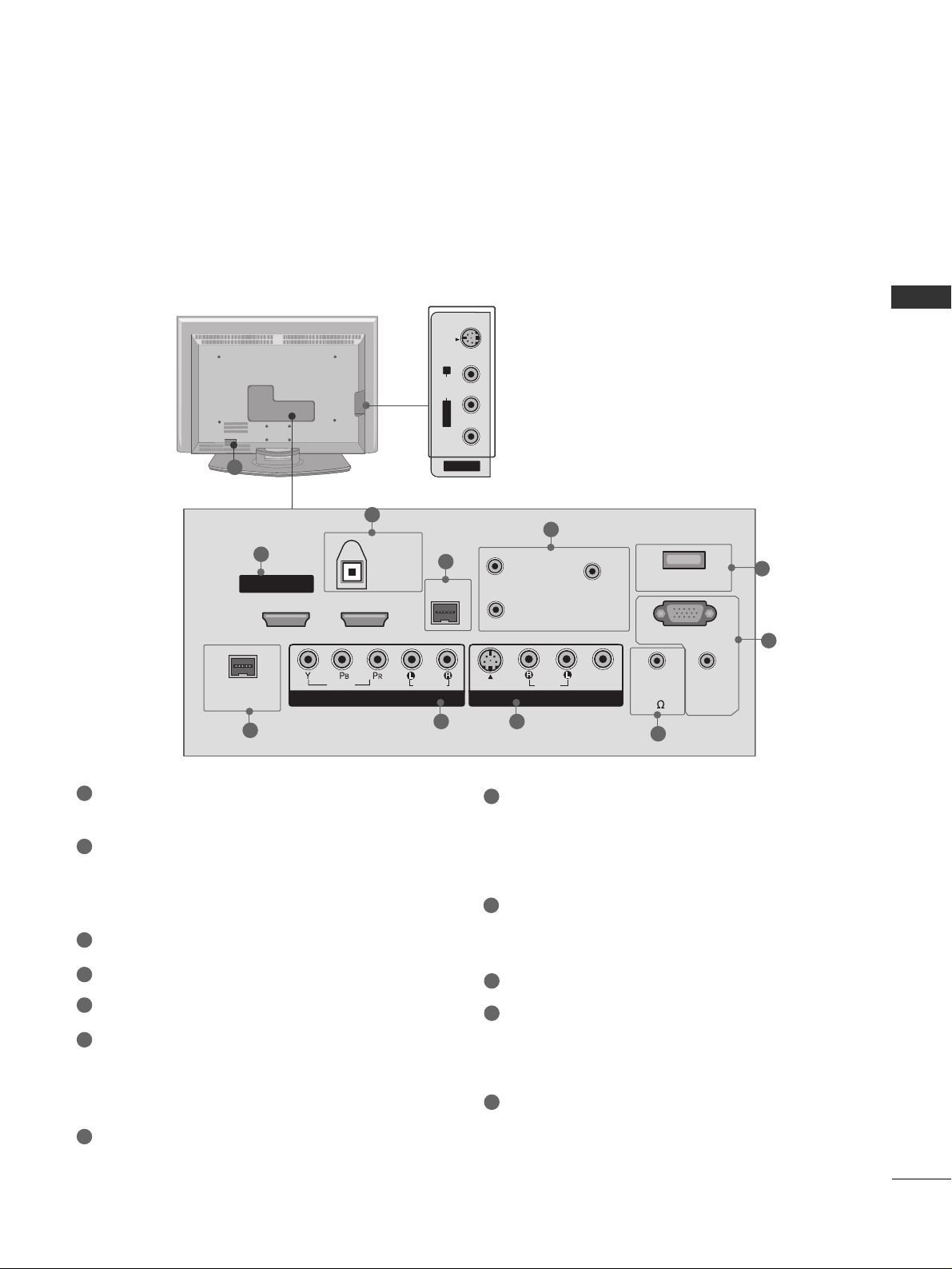
Back Panel Information . . . . . . . . . . . . . . . . . . . . . . . . . . . . . . . . . . . . . . 9
Back Co er for Wire Arrangement . . . . . . . . . . . . . . . . . . . . . 10
Attaching the TV to a Wall . . . . . . . . . . . . . . . . . . . . . . . . . . . . . . . . 11
Swi el Stand . . . . . . . . . . . . . . . . . . . . . . . . . . . . . . . . . . . . . . . . . . . . . . . . . . . . 11
Stand Installation . . . . . . . . . . . . . . . . . . . . . . . . . . . . . . . . . . . . . . . . . . . . 12
VESA Wall Mounting . . . . . . . . . . . . . . . . . . . . . . . . . . . . . . . . . . . . . . . . 13
Desktop Pedestal Installation . . . . . . . . . . . . . . . . . . . . . . . . . . . . 13
Antenna or Cable Connection . . . . . . . . . . . . . . . . . . . . . . . . . . 14
EXTERNAL EQUIPMENT SETUP
HD Recei er Setup . . . . . . . . . . . . . . . . . . . . . . . . . . . . . . . . . . . . . . . . . 15
DVD Setup . . . . . . . . . . . . . . . . . . . . . . . . . . . . . . . . . . . . . . . . . . . . . . . . . . . . . . 18
VCR Setup . . . . . . . . . . . . . . . . . . . . . . . . . . . . . . . . . . . . . . . . . . . . . . . . . . . . . 20
Other A/V Source Setup . . . . . . . . . . . . . . . . . . . . . . . . . . . . . . . . 22
Digital Audio Output . . . . . . . . . . . . . . . . . . . . . . . . . . . . . . . . . . . . . . 23
PC Setup . . . . . . . . . . . . . . . . . . . . . . . . . . . . . . . . . . . . . . . . . . . . . . . . . . . . . . . . 24
WATCHING TV / CHANNEL CONTROL
Remote Control Functions . . . . . . . . . . . . . . . . . . . . . . . . . . . . . . . 26
Turning On TV . . . . . . . . . . . . . . . . . . . . . . . . . . . . . . . . . . . . . . . . . . . . . . . . 28
Channel Selection . . . . . . . . . . . . . . . . . . . . . . . . . . . . . . . . . . . . . . . . . . . 28
Volume Adjustment . . . . . . . . . . . . . . . . . . . . . . . . . . . . . . . . . . . . . . . . . 28
On-Screen Menus Selection . . . . . . . . . . . . . . . . . . . . . . . . . . . . 29
Channel Setup . . . . . . . . . . . . . . . . . . . . . . . . . . . . . . . . . . . . . . . . . . . . . . . . 30
- Auto Scan (EZ Scan) . . . . . . . . . . . . . . . . . . . . . . . . . . . . . . . . 30
- Add / Delete Channel (Manual Scan) . . . . . . . . . 31
- Channel Editing . . . . . . . . . . . . . . . . . . . . . . . . . . . . . . . . . . . . . . . . 32
DTV Signal Strength . . . . . . . . . . . . . . . . . . . . . . . . . . . . . . . . . . . . . . . . 33
Channel Label . . . . . . . . . . . . . . . . . . . . . . . . . . . . . . . . . . . . . . . . . . . . . . . . . 34
PICTURE CONTROL
Watching PIP (Picture-In-Picture)/
POP (Picture-Out-Picture) . . . . . . . . . . . . . . . . . . . . . . . . . . . . . . . 35
Picture Size (Aspect Ratio) Control . . . . . . . . . . . . . . . . . . 37
Preset Picture Settings . . . . . . . . . . . . . . . . . . . . . . . . . . . . . . . . . . . . . 38
- EZ Picture - Preset . . . . . . . . . . . . . . . . . . . . . . . . . . . . . . . . . . . . 38
- Color Tone - Preset. . . . . . . . . . . . . . . . . . . . . . . . . . . . . . . . . . . 39
Manual Picture Adjustment . . . . . . . . . . . . . . . . . . . . . . . . . . . . . . 40
- EZ Picture - User Mode . . . . . . . . . . . . . . . . . . . . . . . . . . . . 40
- Color Tone - User Mode . . . . . . . . . . . . . . . . . . . . . . . . . . . 41
XD - Picture Impro ement Technology . . . . . . . . . . . . . 42
Ad anced - Cinema 3:2 Pull Down Mode . . . . . . . . . 43
Ad anced - Black (Darkness) Le el . . . . . . . . . . . . . . . . . . . 44
Picture Reset . . . . . . . . . . . . . . . . . . . . . . . . . . . . . . . . . . . . . . . . . . . . . . . . . 45
SOUND & LANGUAGE CONTROL
Auto Volume Le eller (EZ SoundRite) . . . . . . . . . . . . . . . 46
Preset Sound Setting (EZ Sound) . . . . . . . . . . . . . . . . . . . . . 47
Sound Setting Adjustment - User Mode . . . . . . . . . . . 48
Balance Adjustment . . . . . . . . . . . . . . . . . . . . . . . . . . . . . . . . . . . . . . . . 49
TV Speakers On/Off Setup . . . . . . . . . . . . . . . . . . . . . . . . . . . . . . 50
Stereo/SAP Broadcasts Setup . . . . . . . . . . . . . . . . . . . . . . . . . . 51
Audio Language . . . . . . . . . . . . . . . . . . . . . . . . . . . . . . . . . . . . . . . . . . . . . . 52
On-Screen Menus Language Selection . . . . . . . . . . . . . . 53
Caption/Text . . . . . . . . . . . . . . . . . . . . . . . . . . . . . . . . . . . . . . . . . . . . . . . . . . 54
- Analog Broadcasting System Captions . . . . . . . 54
- Digital Broadcasting System Captions . . . . . . . . 55
Caption Option . . . . . . . . . . . . . . . . . . . . . . . . . . . . . . . . . . . . . . . . . . . . . 56