LG 42PG60UR-TA User manual

LCD TV PLASMA TV
OWNER’S MANUAL
LCD TV MODELS
32LG6***
37LG6***
42LG6***
47LG6***
42LG7***
47LG7***
52LG7***
32LG8***
42LG8***
PLASMA TV MODELS
50PG3***
42PG6***
50PG6***
60PG6***
50PG7***
60PG7***
Please read this manual carefully before operating your set.
Retain it for future reference.
Record model number and serial number of the set.
Refer to the label on the back cover and quote this
information.
To your dealer when requiring service.
ENGLISH


1
ACCESSORIES
ACCESSORIES
Ensure that the following accessories are included with your TV
If an accessory is missing, please contact the dealer where you purchased the product
■
Image shown may differ from your TV.
Owner's
Manual
Owner’s manual
Owner’s Manual
Batteries
MUTE
RETURN
AVMODE
FAV
TV
INPUT
STB
POWER
Q. MENU
MENU
OK
P
123
456
78
0
9
LIST
Q.VIEW
DVD
TIMESIZE
UPDA
TE
REVEAL
INDEX
HOLDTEXTPIP
Remote Control
Power Cord
Polishing Cloth
Polishing cloth for use on the screen
This feature is not available for all models.
Lightly wipe any stains or fingerprints on the
surface of the TV with the polishing cloth.
Do not use excessive force. This may
cause scratching or discolouration.
LLDD TTVV mmooddeellss
Cable management clip
(Refer to p.15)
PPLLAASSMMAA TTVV mmooddeellss
(only 50/60PG6 ,
50/60PG7 )
Protection cover
(Refer to p.12)
32LG6 : 3EA
37LG6 : 4EA
(only 32/37LG6 )
4EA 2EA
(only 42LG6 )
4EA
1EA
bolts for stand assembly (Refer to p. 11)
4-bolts for stand assembly
Refer to p. 10
(only 42PG6 )
(only 50PG3 )
or
42PG6 : 1EA
50PG3 : 2EA only
Cable management clip
protection cover
(Refer to p.10)
Cable Holder
Only 32/37/42/47LG6
Only 42/47/52LG7 , 32/42LG8
Bolts for stand assembly
(Refer to p.12)
x 4
x 4
(42LG7 , 32/42LG8 only)
(except
50PG3 )
1-screw for stand fixing
(Refer to p.9)
(32/42LG8 only)
Protection cover
or
Ferrite core can be used to reduce the electromagnetic
wave when connecting the power cord.
The closer the location of the ferrite core to the power
plug, the better it is. Install the power plug closely.
or
This feature is not available for
all models.
Ferrite Core
Use of ferrite core (
This feature is not available for all models.
)

2
CONTENTS
CONTENTS
Watching PIP(Picture-in-Picture) .............................63
Picture Size (Aspect Ratio) ontrol.........................64
Preset Picture Settings
- Picture Mode-Preset............................................66
- Auto olour Tone ontrol( ool/Medium/Warm)
67
Manual Picture Adjustment
- Picture Mode-User Option................................68
- olour Tone - User Option...............................69
-
Picture Improvement Technology
...................70
Advanced - Gamma......................................................71
Advanced - Film Mode/Real inema.......................72
Advanced - Black(Darkness) Level...........................73
Eye are..........................................................................74
Advanced-TruMotion ...................................................75
Picture Reset..................................................................76
TruMotion Demo ..........................................................77
Power Indicator..............................................................78
Image Sticking Minimization(ISM) Method...........79
Power Saving Picture Mode .......................................80
Factory Reset .................................................................81
Remote ontrol Key Functions..................................38
Turning on the TV....................................................... 40
Programme Selection ................................................. 40
Volume Adjustment......................................................40
Quick Menu................................................................... 41
On Screen Menus Selection and Adjustment ......42
Auto Programme Tuning............................................ 43
Manual Programme Tuning....................................... 44
Fine Tuning .....................................................................45
Assigning a Station Name..........................................46
Booster............................................................................47
Programme Edit ........................................................... 48
PICTURE CONTROL
WATCHING TV / PROGRAMME CONTROL
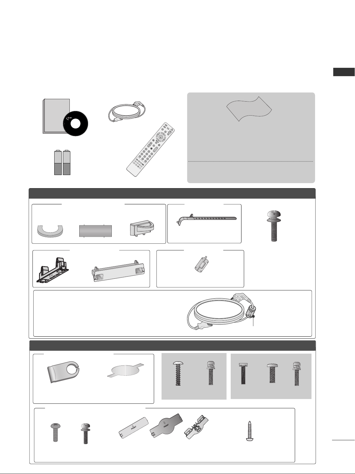
AAEESSSSOORRIIEESS.....................................................1
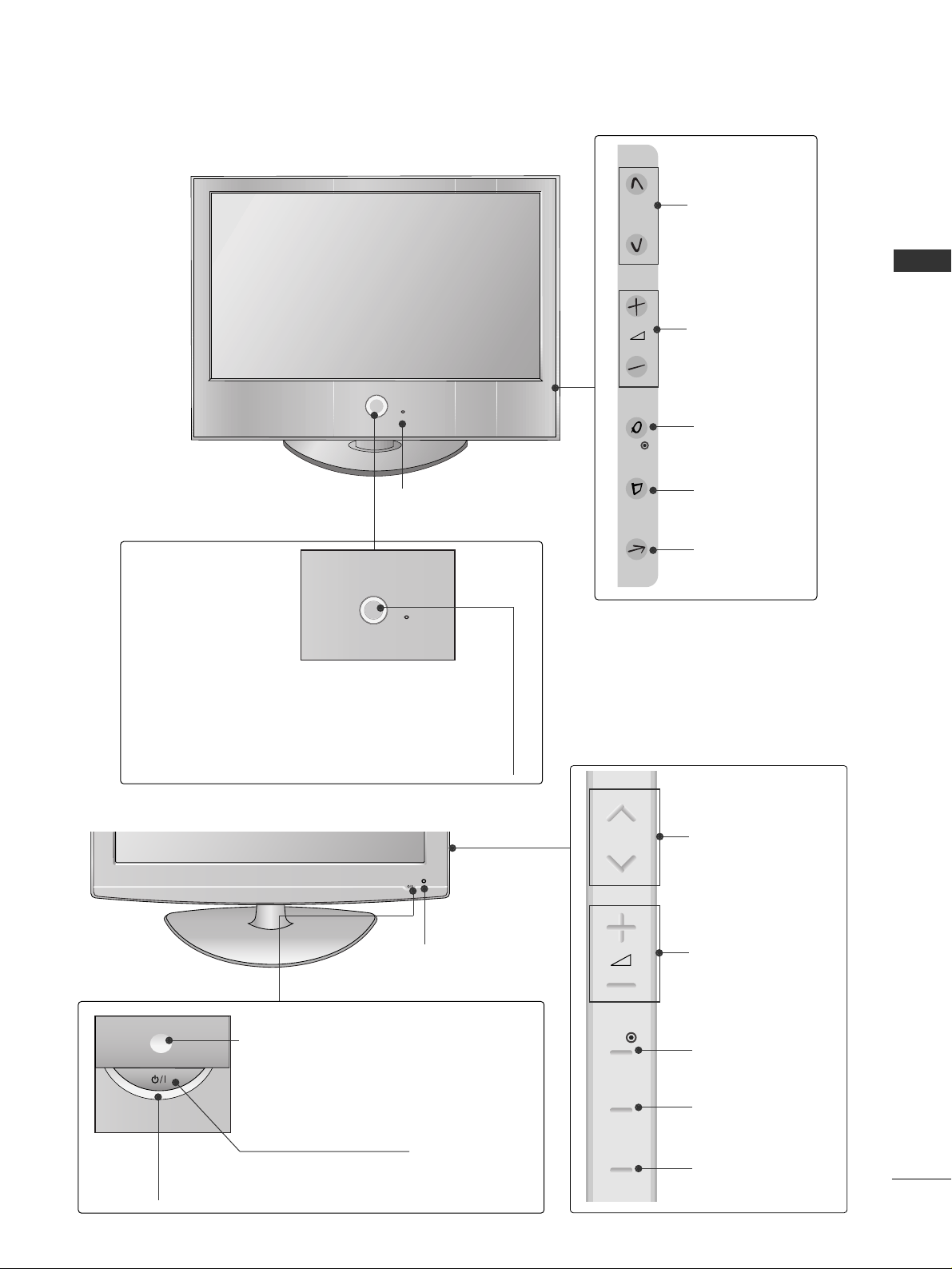
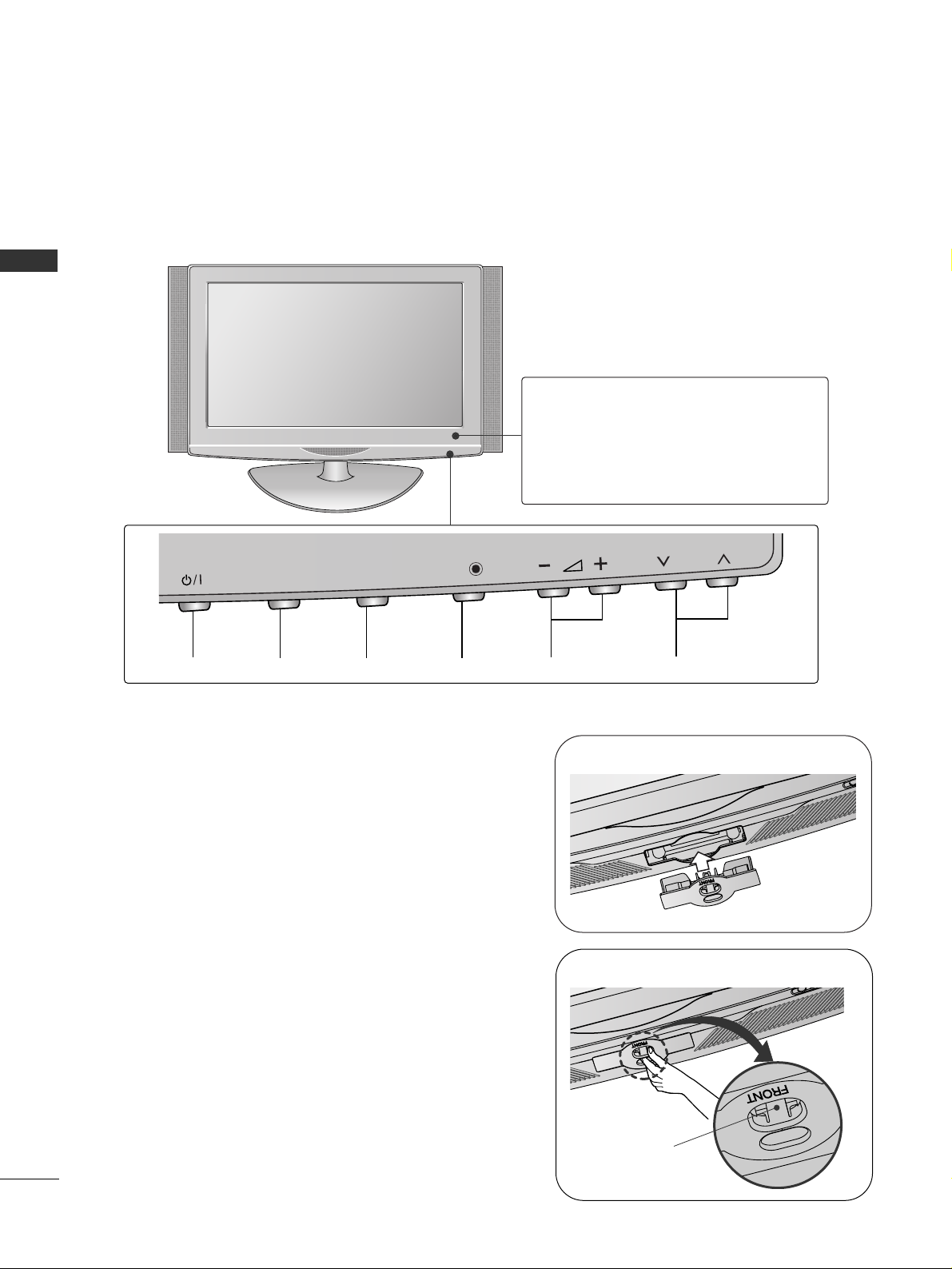
Front Panel ontrols................................................. 4
Back Panel Information ............................................ 7
Attaching the TV to a desk ..................................... 9
Stand Installation..................................................... 10
Back over for Wire Arrangement....................... 13
Please set it up carefully so the product
does not fall over. .....................................................16
Desktop Pedestal Installation ............................... 17
Wall Mount: Horizontal installation..................... 17
Antenna onnection............................................... 18
PREPARATION
EXTERNAL EQUIPMENT SETUP
HD Receiver Setup .......................................................19
DVD Setup .................................................................... 22
V R Setup..................................................................... 25
Other A/V Source Setup .......................................... 28
External Stereo............................................................. 29
AV Output Setup ........................................................ 30
P Setup .........................................................................31
- Screen Setup for P Mode................................34
When connecting the USB device...........................55
Photo List........................................................................56
Music List........................................................................58
Movie List
.........................................................................60
Divx Registration ode
...................................................62
TO USE THE USB DEVICE
Favourite Programme .................................................. 49
Selecting the Programme List.................................. 50
.................................................................. 51
Key lock.......................................................................... 53
AV Mode .........................................................................54

3
CONTENTS
SOUND & LANGUAGE CONTROL
Auto Volume Leveler ....................................................82
Preset Sound Settings - Sound Mode ....................83
Sound Setting Adjustment - User Mode ...............84
Balance............................................................................85
TV Speakers On/Off Setup .......................................86
Selecting Audio Out....................................................86
Sliding Mode..................................................................87
I/II
- Stereo/Dual Reception....................................... 88
- NI AM Reception ....................................................... 89
- Speaker Sound Output Selection.................... 89
On-Screen Menu Language Selection
...................... 90
APPENDIX
Troubleshooting............................................................98
Maintenance ...............................................................100
Product Specifications ..............................................101
Programming the Remote ontrol ...................... 103
IR odes ..................................................................... 105
External ontrol Through RS-232 ................... 107
TIME SETTING
lock Setup....................................................................91
Auto On/Off Timer Setting .......................................92
Sleep Timer Setting......................................................93
Auto Shut-off Setting ..................................................94
TELETEXT
Switch On/Off .............................................................95
SIMPLE Text....................................................................95
TOP Text.........................................................................96
FASTEXT.........................................................................96
Special Teletext Functions..........................................97

4
FRONT PANEL CONTROLS
PREPARATION
PREPARATION
■
This is a simplified representation of the front panel. Image shown may differ from your TV.
■
If your product has a protection film attached, remove the film and then wipe the product with a polishing
cloth.
Plasma TV Models
OK
MENU
INPUT P
OK
MENU
INPUT P
Remote Control Sensor
POWER
Power/Standby Indicator
• illuminates red in standby mode.
• illuminates green when the TV is
switched on.
PROGRAMMEVOLUMEMENU OKINPUT
OKOK
MENUMENU
INPUTINPUT P
Swivel Stand
This feature is not available for all models
After installing the TV, you can adjust the TV set manually to the left or right direction by 20 degrees to suit
your viewing position

5
PREPARATION
32/37/42/47LG6
OK
P
MENU
INPUT
PROGRAMME
VOLUME
OK
MENU
INPUT
Intelligent Sensor
Adjusts picture according to the
surrounding conditions
POWER
Remote Control Sensor
Power/Standby Indicator
• illuminates red in standby mode.
• illuminates White when the TV is switched on.
Note: You can adjust Power Indicator in the Option menu.
POWER
Power/Standby Indicator
• illuminates red in standby mode.
• illuminates blue when the TV is switched on.
Note: You can adjust PPoowweerr IInnddiiccaattoorrin the
Option menu.
P
MENU
INPUT
OK
PROGRAMME
VOLUME
OK
MENU
INPUT
Intelligent Sensor
Adjusts picture according to the
surrounding conditions.
Remote Control Sensor
42/47/52LG7
LCD TV Models

6
PREPARATION
32/42LG8***
PROGRAMME
VOLUME
MENU OK
INPUT
POWER
OK
MENU
INPUT P
OK
MENU
INPUT P
Remote Control Sensor
Power/Standb Indicator
• illuminates red in standby mode.
• illuminates blue when the TV is switched on.
Note: You can adjust PPoowweerr IInnddiiccaattoorrin
the Option menu.
Not Using the Desk-t pe Stand
■
Image shown may differ from your TV.
When installing the wall-mounted unit, use the
protection cover for desk-t pe stand installation.
Insert the PPRROOTTEECCTTIIOONN CCOOVVEERRinto the TV
until clicking sound.
32LG8***
How to remove the portection cover
■
Image shown may differ from your TV.
Press the A part of protection cover as shown and
pull it backward.
32LG8***
A
* Give extra space for installing speakers on both sides of the TV to allow for free movement.
(onl 42LG8***)

7
PREPARATION
BACK PANEL INFORMATION
■
This is a simplified representation of the back panel. Image shown may differ from your TV.
Plasma TV Models
HDMI INHDMI/DVI IN
12
1
2
AUDIO
(RGB/DVI)
RGB
(PC)
RG
B I
N
CO
MP
O
NENT I
N
ANTENNA
IN
RS-232C IN
(CONTROL)
A
U
DI
O
AV IN 2
L/
MONO
R
AUDIO
AV
VIDEO
IN 1
OU
T
VARIABLE AUDIO OUT
1
56
HDMI Input
onnect a HDMI signal to HDMI IN.
Or DVI(VIDEO)signal to HDMI/DVI port with DVI
to HDMI cable.
RGB/Audio Input
onnect the monitor output from a P to the
appropriate input port.
Audio/Video Input (AV IN 1)
onnect audio/video output from an external
device to these jacks.
AV Output
onnect second TV or monitor to the AV OUT
socket on the TV.
Variable Audio Output
onnect an external amplifier or add a subwoofer
to your surround sound system.
Component Input
onnect a component video/audio device to
these jacks.
Antenna Input
onnect RF antenna to this jack.
Power Cord Socket
This TV operates on an A power. The voltage is
indicated on the Specifications page. Never
attempt to operate the TV on D power.
RS-232C Input (CONTROL) Port
onnect the serial port of the control devices to
the RS-232 jack.
(This feature is not available for all models.)
1
2
3
4
5
6
7
8
28
3
HDMI INHDMI/DVI IN
12
1
2
AUDIO
(RGB/DVI)
RGB IN
(PC)
COMPONENT IN
ANTENNA
IN
RS-232C IN
VIDEO AUDIO
AV IN 2
AV IN 1
L/
L/
MONO
MONO
R
AUDIO
AUDIO
VIDEO
VIDEO
VARIABLE AUDIO OUT
VARIABLE AUDIO OUT
VIDEO
VIDEO
AV OUT
(CONTROL)
12
4
3 4
8
56
42/50/60PG6 50PG3 , 50/60PG7
AV IN 2
7
AV IN 2
AV IN 2
3
USB Input
HDMI Input
onnect a HDMI signal to
HDMI IN.
S-Video Input
onnect S-Video out
from an S-VIDEO device.
Audio/Video Input
onnect audio/video
output from an external
device to these jacks.

8
PREPARATION
HDMI INHDMI/DVI IN
1
1
2
2
AUDIO
RGB
(PC)
RGB IN
COMPONENT IN
AUDIO
VIDEO
(RGB/DVI)
L/L/MONOMONO
R
AUDIOAUDIO
AV
VIDEOVIDEO
IN 1
OUT
VARIABLE AUDIO OUTVARIABLE AUDIO OUT
AV IN 2
ANTENNA
IN
AV IN 2
12
L/MONO
R
AUDIO
VIDEO
VARIABLE
AUDIO OUT
ANTENNA
IN
2
1
5
LCD TV Models
12
L/MONO
R
AUDIO
VIDEO
VARIABLE AUDIO OUT
AV IN 2
3
AV IN 2
12
L/MONO
R
AUDIO
VIDEO
VARIABLE
AUDIO OUT
ANTENNA
IN
6
12
L/MONO
R
AUDIO
VIDEO
VARIABLE AUDIO OUT
AV IN 2
AV IN 2
12
L/MONO
R
AUDIO
VIDEO
VARIABLE
AUDIO OUT
ANTENNA
IN
42/47LG6 , 42/47/52LG7
32/37LG6
3
4
12
L/MONO
R
AUDIO
VIDEO
VARIABLE AUDIO OUT
AV IN 2
AV IN 2
HDMI INHDMI/DVI IN
1
1
2
2
AUDIO
RGB
(PC)
RGB IN
COMPONENT IN
AUDIO
VIDEO
(RGB/DVI)
L/L/MONOMONO
R
AUDIOAUDIO
AV
VIDEOVIDEO
IN 1
OUT
VARIABLEVARIABLE
AUDIO OUTAUDIO OUT
ANTENNA
IN
2
1
56
3
4
42/47/52LG7
32/37/42/47LG6
77
USB Input
HDMI Input
onnect a HDMI signal
to HDMI IN.
S-Video Input
onnect S-Video out
from an S-VIDEO device.
Audio/Video Input
onnect audio/video
output from an external
device to these jacks.
PREPARATION
AV IN 2
HDMI INHDMI/DVI IN
12
ANTENNA
IN
12
VIDEO
AUDIO
RGB
(PC)
RGB IN
(RGB/DVI)
AUDIO
AV
L(L(MONO)MONO)
R
AUDIOAUDIO
VIDEOVIDEO
IN1
OUT
VARIABLE AUDIO OUTVARIABLE AUDIO OUT
COMPONENT
IN
32/42LG8
OK
MENU
INPUT P
AV IN 2
AV IN 2
USB IN
L(MONO)
R
AUDIO
VIDEO
VARIABLE AUDIO OUT
3
4
15
2
6
USB Input
S-Video Input
onnect S-Video out
from an S-VIDEO device.
Audio/Video Input
onnect audio/video
output from an external
device to these jacks.
7

9
PREPARATION
HDMI Input
onnect a HDMI signal to HDMI IN.
Or DVI(VIDEO)signal to HDMI/DVI port with DVI
to HDMI cable.
(HDMI IN 3 is available for 42/47LG6***,
42/47/52LG7***)
RGB/Audio Input
onnect the monitor output from a P to the
appropriate input port.
Audio/Video Input
onnect audio/video output from an external
device to these jacks.
AV Output
onnect second TV or monitor to the AV OUT
socket on the TV.
Variable Audio Output
onnect an external amplifier or add a subwoofer
to your surround sound system.
Component Input
onnect a component video/audio device to
these jacks.
Antenna Input
onnect RF antenna to this jack.
Power Cord Socket
This TV operates on an A power. The voltage is
indicated on the Specifications page. Never
attempt to operate the TV on D power.
1
2
3
4
5
6
7
ATTACHING THE TV TO A DESK (Only 32/42LG8***)
The TV must be attached to desk so it cannot be pulled in a forward/backward direction, potentially causing
injury or damaging the product. Use only an attached screw.
1-Screw
(provided as parts of the product)
Desk
Stand
WARNING
!
G To prevent TV from falling over, the TV should be securely attached to the floor/wall per installation
instructions Tipping, shaking, or rocking the machine may cause injury

10
PREPARATION
PREPARATION
STAND INSTALLATION
■
Image shown may differ from your TV.
arefully place the TV screen side down on a
cushioned surface to protect the screen from
damage.
Assemble the TV as shown.
Fix the 4 bolts securely using the holes in the
back of the TV.
1
2
3
only 42PG6
When assembling the desk type stand, check whether the bolt is fully tightened.
(If not tightened fully, the product can tilt forward after the product installation.) If you tighten the bolt with
excessive force, the bolt can deviate from abrasion of the tightening part of the bolt.
Plasma TV models
Not Using the Desk-type Stand
When installing the wall-mounted unit, use the
protection cover for desk-type stand installation
Insert the PROTECTION COVER into the TV until
clicking sound
■
Image shown may differ from your TV.

11
PREPARATION
1 3
4
arefully place the TV screen side down on a
cushioned surface to protect the screen from
damage.
2Assemble the parts of the SSttaanndd BBooddyywith
oovveerr BBaasseeof the TV.
Assemble the TV as shown.
Fix the 4 bolts securely using the holes in the
back of the TV.
Stand Body
Cover Base
32LG6
37LG6
Stand Body
Cover Base
42LG6
Stand Body
Cover Base
only 32/37/42LG6

12
PREPARATION
1 3
4
arefully place the TV screen side down on a
cushioned surface to protect the screen from
damage.
2Assemble the parts of the SSttaanndd BBooddyywith
the oovveerr BBaasseeof the TV.
Assemble the TV as shown.
Fix the 4 bolts securely using the holes in the
back of the TV.
Stand Body
Cover Base
only 42LG7 , 32/42LG8
Not Using the Desk-type Stand
When installing the wall-mounted unit, use the protection cover for desk-type stand installation
After removing the protection paper from the
protection cover, adhere it to the TV as shown
■
Image shown may differ from your TV.
Insert the PPRROOTTEETTIIOONN OOVVEERRinto the TV
until clicking sound.
42/47/52LG7 , 42LG8
32/37/42/47LG6

13
PREPARATION
BACK COVER FOR WIRE ARRANGEMENT
onnect the cables as necessary.
To connect additional equipment, see the
EExxtteerrnnaall EEqquuiippmmeenntt SSeettuuppsection.
1
Install the AABBLLEE MMAANNAAGGEEMMEENNTT LLIIPPas shown.
2
Hold the AABBLLEE MMAANNAAGGEEMMEENNTT LLIIPPwith both hands and pull it upward.
NOTE
!
GGDo not use the CABLE MANAGEMENT CLIP to lift the TV.
- If the TV is dropped, you may be injured or the TV may be damaged.
How to remove the cable management clip
■
Image shown may differ from your TV.
CABLE MANAGEMENT CLIP
onnect the cables as necessary.
To connect additional equipment, see the
EExxtteerrnnaall EEqquuiippmmeenntt SSeettuuppsection.
1
Install the AABBLLEE MMAANNAAGGEEMMEENNTT LLIIPPas shown.
2
CABLE MANAGEMENT CLIP
42PG6 50/60PG6 , 50/60PG7
50/60PG6 , 50/60PG7
42PG6
Separate ABLE MAN-
AGEMENT from TV by
pressing two latches.
* For the 42PG6*** model, press the center of the ABLE MANAGEMENT LIP and then lift up it.
Fix the aabbllee HHoollddeerr
as shown and bundle
the cables.

14
PREPARATION
PREPARATION
■
Image shown may differ from your TV.
How to remove the cable management clip
onnect the cables as necessary.
To connect additional equipment, see the
EXTERNAL EQUIPMENT SETUP section.
Install the CABLE MANAGEMENT CLIP as
shown.
If your TV has the ABLE HOLDER, install it
as shown and bundle the cables.
1
2
NOTE
!
GGDo not use the CABLE MANAGEMENT CLIP to lift the TV.
- If the TV is dropped, you may be injured or the TV may be damaged.
Hold the AABBLLEE MMAANNAAGGEEMMEENNTT LLIIPPwith both hands and pull it upward.
50PG3
CABLE MANAGEMENT CLIP
CABLE HOLDER

15
PREPARATION
32/37/42/47LG6
onnect the cables as necessary.
To connect additional equipment, see the EExxtteerrnnaall
EEqquuiippmmeenntt SSeettuuppsection.
1
2
Align the hole with the tab on the AABBLLEE
MMAANNAAGGEEMMEENNTT LLIIPP.
Turn the AABBLLEE MMAANNAAGGEEMMEENNTT LLIIPPas
shown.
Note: This cable management can be broken
by excessive pressure.
onnect the cables as necessary.
To connect additional equipment, see the
External Equipment Setup section of the manual.
1
Open the AABBLLEE MMAANNAAGGEEMMEENNTT LLIIPPas
shown and manage the cables.
2
CABLE MANAGEMENT CLIP
Fit the AABBLLEE MMAANNAAGGEEMMEENNTT LLIIPPas
shown.
3
42/47/52LG7 , 32/42LG8

16
PREPARATION
PREPARATION
PLEASE SET IT UP CAREFULLY SO THE PRODUCT DOES NOT
FALL OVER
AYou should purchase necessary components to fix the TV to the wall on the market
APosition the TV close to the wall to avoid the possibility of it falling when pushed
AThe instructions shown below are a safer way to set up the TV, which is to fix it to the wall, avoiding the
possibility of it falling forwards if pulled This will prevent the TV from falling forward and causing injury
This will also prevent the TV from damage Ensure that children do not climb or hang from the TV
NOTE
!
G When moving the TV undo the cords first
G Use a platform or cabinet string and large enough to support the size and weight of the TV
G To use the TV safely make sure that the height of the bracket on the wall and on the TV is the same
3
1
2
Use the eye-bolts or TV brackets/bolts to fix the product to the wall as shown in the picture.
(If your TV has bolts in the eyebolts, loosen then bolts.)
* Insert the eye-bolts or TV brackets/bolts and tighten them securely in the upper holes.
Secure the wall brackets with bolts to the wall.
Ensure that both brackets are even.
3Use a strong cord to secure the TV.
Secure the cord in such a way that it becomes taught when the TV is in position.
2
1
2
1

17
PREPARATION
■The TV can be installed in various ways such as on a wall, or on a desktop etc
■The TV is designed to be mounted horizontally
DESKTOP PEDESTAL INSTALLATION
For adequate ventilation allow a clearance of 4” (10cm) all around the TV .
4 inches
4 inches
4 inches
4 inches
Power Supply
Circuit breaker
EARTHING
Ensure that you connect the earth wire to prevent possi-
ble electric shock. If grounding methods are not possible,
have a qualified electrician install a separate circuit breaker.
Do not try to earth the TV by connecting it to telephone
wires, lightening rods or gas pipes.
WALL MOUNT: HORIZONTAL INSTALLATION
For adequate ventilation allow a clearance of 4” (10cm) all around the TV We recommend that you
use a wall mounting bracket of LG brand when mounting the TV to a wall
4 inches
4 inches
4 inches
4 inches
4 inches

18
PREPARATION
ANTENNA
IN
AV IN 2
PREPARATION
ANTENNA CONNECTION
■For optimum picture quality, adjust antenna direction.
■An antenna cable and converter are not supplied.
Multi-family Dwellings/Apartments
(Connect to wall antenna socket)
Single-family Dwellings /Houses
(Connect to wall jack for outdoor antenna)
Outdoor
Antenna
Wall
Antenna
Socket
RF Coaxial Wire (75 ohm)
Antenna
UHF
VHF
■In poor signal areas, to achieve better picture quality it may be necessary to install a signal amplifier to the
antenna as shown above.
■If signal needs to be split for two TVs, use an antenna signal splitter for connection.
■To prevent damage do not connect to the mains outlet until all connections are made between the devices
AV 1 AV 2
ANTENNA
IN
AV 1 AV 2
ANTENNA
IN
ANTENNA
IN
AV IN 2
Signal
Amplifier
Other manuals for 42PG60UR-TA
1
This manual suits for next models
20
Table of contents
Other LG LCD TV manuals