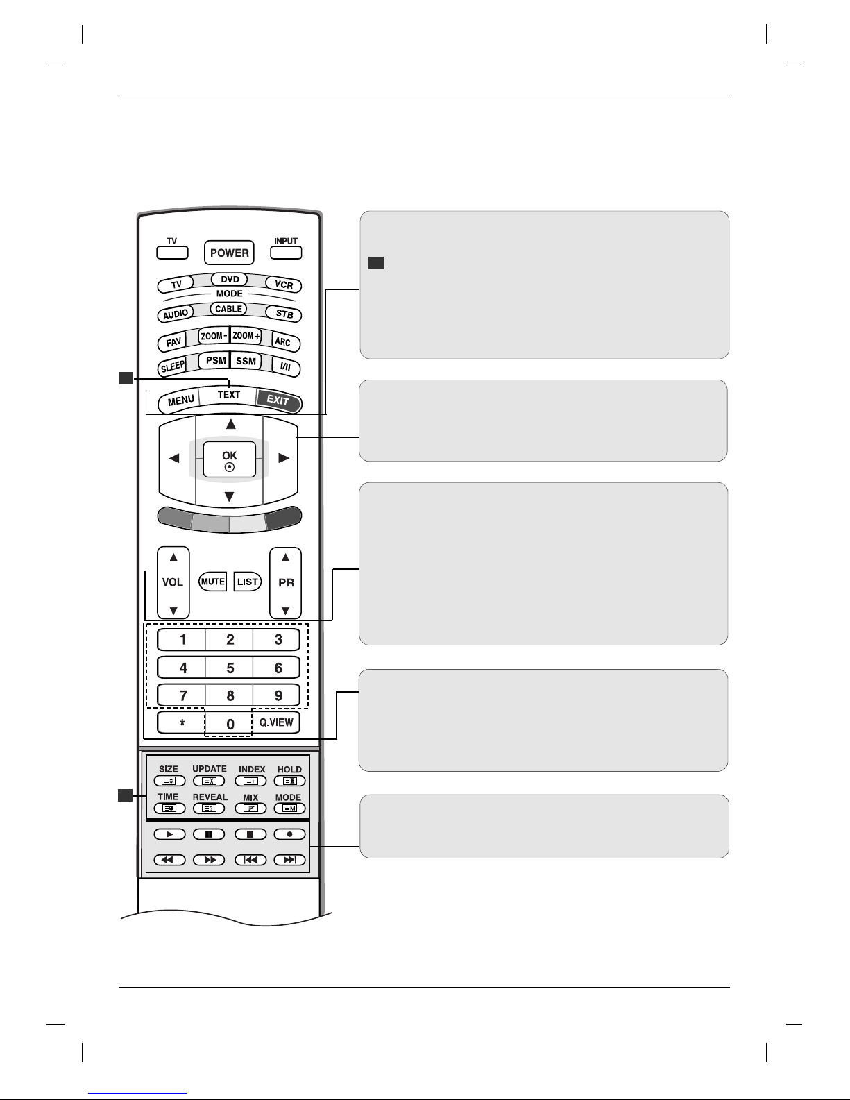
LG RZ-37LZ55 User manual

LCD TV
Please read Information Manual included together
before reading this manual and operating your set.
Retain it for future reference.
Record model number and serial number of the set.
See the label attached on the back cover and quote
this information to your dealer when you require service.
P/NO : 38289U0496C(0508-REV00)
Printed in Korea
OWNER’S MANUAL
MODEL: RZ-37LZ55

2
Owner’s Manual Power Cord Remote Control / Batteries
Ensure that the following accessories are included with your TV. If any accessory is missing, please contact the
dealer from where you purchased the product.
Accessories
D-SUB cable (PC) Audio cable (PC)
Twister Holder
2-TV Brackets, 2-Wall Bracket2-TV Bracket Bolts

3
ENGLISH
Contents
Contents
Introduction
Operation
2 Accessories
5 Controls
6 Connection Options
7 Remote Control Key Functions
Setting up
TV stations
Basic operation
Installation
10 Basic Connection
12 External Equipment Connections
12 Antenna Connection
12 Headphone Socket
13 VCR Setup
15 DVD Setup
16 STB ( Set-Top Box) Setup
18 Cable TV Setup
19 External AV Source Setup
20 PC Setup
21 Supported display resolution
21 Power Cord Connection
22 Turning On/Off the TV
22 Volume Adjustment
22 Programme selection
22
On screen language selection
23 How to adjust the OSD screen
24 Auto programme tuning
25 Manual programme tuning
26 Fine tuning
26 Assigning a station name
27 Programme edit
28
Favourite programme
28
Calling the programme table
29
PSM (Picture Status Memory)
29 CSM (Colour Status Memory)
30 Function
30 ACM (Active Colour Management)
31 sRGB
31 Manual Picture Adjustment
32 SSM (Sound Status Memory)
32 SRS WOW
33 AVL (Auto Volume leveler)
33 Manual Sound Adjustment
34 TV Speaker
35 I/II
36
Clock Setup
36 On/Off Time
37 Auto Sleep
37
Sleep Timer
Picture adjustment
Sound adjustment
Time menu

4
Reference
Operation
38 Input
38 Child Lock
39 Demo
40 Auto Configure
40 Manual Configure
41 XGA Mode
41 Picture Size Zoom
42 Picture format (ARC)
43 Screen Position
43 Cinema
44 NR (Noise Reduction)
45 Reset to original factory value (Initializing)
46 Switch on/off
46 SIMPLE text
46 TOP text (option)
47 FASTEXT
47 Special teletext functions
Special Menu
Screen Menu
Teletext
48 External Control Device Setup ; RS-232C
52 IR codes
54 Programming the Remote control
55 Programming Codes
57 Troubleshooting Checklist
59 Product Specifications

5
ENGLISH
- This is a simplified representation of front panel.
- Here shown may be somewhat different from your TV.
Remote Control Sensor
Power/Standby Indicator
(rr)
• illuminates red in standby mode.
• illuminates green when the set is
switched on.
Controls
Controls
Introduction
Introduction
Programme
(
EE
/
DD
) Buttons
Volume (F / G)
Buttons
OK Button
Menu Button
INPUT Button
ON/OFF Button

6
COMPONENT input
(Y,PB,PR/ Audio)
Headphone Socket
PC SOUND Input
Remote Control Port
Euro Scart Socket
(AV1/AV2)
HDMI (High Definition Multimedia Interface)/DVI
input
RS-232C Input Variable AUDIO OUT ports
RGB Input
AV3 (Video/Audio) Input
Antenna Input
AC Input
Connection Options
Connection Options
Introduction
Introduction

7
ENGLISH
MODE
Selects the remote operating modes. :TV, DVD, VCR, AUDIO, CABLE
or STB
FAVOURITE
Displays the se
lected favourite programme
(Refer to p.28).
ZOOM - / ZOOM +
Enlarges or reduces the main picture size.
ARC
Selects your desired picture format (Refer to p.42).
SLEEP
Sets the sleep timer. (Refer to p.37)
PSM (Picture Status Memory)
Recalls your preferred picture setting. (Refer to p.29)
SSM (Sound Status Memory)
Recalls your preferred sound setting. (Refer to p.32)
I/II
• Selects the sound output.
*
COLOURED BUTTONS : These buttons are used for teletext (only
TELETEXT models) or Programme edit.
Remote Control Key Functions
Introduction
Introduction
TV
Returns to TV viewing from any mode.
POWER
switches the set on from standby or off to standby.
INPUT
If you press the button once, the input source OSD
will appear on screen as shown. Press the DD / EEbut-
ton and then OK button to select the desired input
source (TV, AV 1 , AV 2 , AV 3 , S-Video, Component,
RGB PC/RGB DTV, or HDMI PC/ HDMI DTV).
TV
AV1
AV2
AV3
S-Video
Component
RGB PC
HDMI PC
TV
Input

8
MENU
Selects a menu.
TELETEXT BUTTONS
These buttons are used for teletext.
For further details, see the ‘Teletext’ section (Refer to p.46).
EXIT
Clears all on-screen displays and returns to TV viewing from any
menu.
DD
/
EE
/ F / G (up / down / left / right)
Selects or adjusts an item in the menu.
OK
Accepts your selection or displays the current mode.
VOL (Volume) D / E
Adjusts the volume.
MUTE
Switches the sound on or off.
LIST
Displays the programme table (Refer to p.28).
PR (Programme) D / E
Selects a programme.
0-9 number buttons
• Selects a programme.
• Selects numbered items in a menu.
Q.VIEW
Returns to the previously viewed programme.
VCR/DVD Control buttons
Controls a LG video cassette recorder or DVD.
1
1
1

9
ENGLISH
Installing Batteries
Open the battery compartment
cover on the back side.
Insert two 1.5V AA size batteries
in correct polarity (+ with +, - with
-). Don’t mix old or used batteries
with new ones.
Close the cover.
* Use a remote control at 7
meter distance and 30 degree
(left/right/up/down) within the
receiving unit scope.
* Dispose of used batteries in the recycle bin to prevent environment.
1
2
3
Remote Control Key Functions
Introduction
Introduction

10
For proper ventilation, allow a clearance of 4" on each side and from
the wall. Detailed installation instructions are available from your
dealer, see the optional Tilt Wall Mounting Bracket Installation and
Setup Guide.
Wall Mount: Horizontal installation
Desktop Pedestal Installation
For proper ventilation, allow a clearance of 4" on each side and from
the wall.
Basic Connection
Basic Connection
Installation
Installation
Connect the cables as necessary.
After connecting the cables neatly,
arrange the cables to the Cable
Holder.
To connect an additional equipment,
see the External equipment
Connections section.
Pull the cables through the hole
on the set and bundle the cables
using the supplied twister holder.

11
ENGLISH
How to join the product assembly to the wall to protect the set tumbling
- Set it up close to the wall so the product doesn’t fall over when it is pushed backwards.
- The instructions shown below is a safer way to set up the product, which is to fix it on the wall so the prod-
uct doesn’t fall over when it is pulled in the forward direction. It will prevent the product from falling for-
ward and hurting people. It will also prevent the product from damage caused by fall. Please make sure
that children don’t climb on or hang from the product.
Notes
• When moving the product to another place undo the ropes first.
• Use a product holder or a cabinet that is big and strong enough for the size and weight of the product.
• To use the product safely make sure that the height of the bracket that is mounted on the wall is same
as that of the product.
2
1
3
Use the bracket and the bolt to fix the product to the wall as shown in the picture.
Secure the bracket with the bolt (not provided as parts of the product, must purchase separately) on
the wall.
Use a sturdy rope (not provided as parts of the product, must purchase separately) to tie the product.
It is safer to tie the rope so it becomes horizontal between the wall and the product.
1
2
3

12
External Equipment Connections
Installation Instruction
Antenna Connection
- For optimum picture quality, adjust antenna direction.
- An antenna cable and converter are not supplied.
To prevent the equipment from damage, never plug in any power cords until you have finished connecting
all equipment.
• In poor signal areas, to get better picture quality, install a sig-
nal amplifier to the antenna as shown to the right.
• If signal needs to be split for two TVs, use an antenna sig-
nal splitter for connection.
Signal
Amplifier
UHF
VHF
Multi-family Dwellings/Apartments
(Connect to wall antenna socket)
Single-family Dwellings /Houses
(Connect to wall jack for outdoor antenna)
Outdoor Antenna
Wall Antenna Socket
VHF Antenna
UHF Antenna
RF Coaxial Wire (75 ohm)
Turn clockwise to tighten.
Headphone Socket
1
2
Plug the headphone into the headphone socket.
To adjust the headphone volume, press the VOL
DD /EEbutton. If you press the MUTE button, the
sound from the headphone is switched off.
- You can listen to the sound through the headphone.
• While you are listening to sound through a headphone,
TV speakers will not be heard.
1

13
ENGLISH
- To avoid picture noise (interference), leave an adequate distance between the VCR and TV.
- Typically a frozen still picture from a VCR. If the 4:3 picture format is used; the fixed images on the sides of the screen
may remain visible on the screen.
VCR Setup
When connecting with an antenna cable
1
2
3
Connect the ANT OUT socket of the VCR to the Antenna socket on the set.
Connect the antenna cable to the ANT IN socket of the VCR.
Press the PLAY button on the VCR and match the appropriate programme between the TV and VCR for viewing.
When connecting with a Scart cable
• If your VCR outputs an AV switching signal via the AV1 or AV2 scart sockets, the set will switch to AV1 input source automati-
cally. But if you want to keep on watching TV mode, press the PR DD /EEor number buttons.
• You can also record programmes received by the TV on video tape.
• The signal type RGB (the signals red, green and blue) can only be selected for the AV1 scart socket and the AV1 input source
can be received. These signals are transmitted, for example, by a pay TV decoder, game machine or photo CD unit, etc and that
digital signal can be recorded via AV1 scart socket.
• If the AV1, AV2 scart sockets have been connected to the VCRs simultaneously, only the AV2 input source can be received.
1
2
3
Connect the scart socket of the VCR to the AV1 scart socket on the set. Please use shielded scart cable.
Insert a video tape into the VCR and press PLAY on the VCR. (Refer to the VCR owner’s manual.)
Select AV 1 input source with using the INPUT button on the remote control.
- If connected to AV2 scart socket, select AV 2 input source.
1
2
TV Back panel
VCR
VCR
1
TV Back panel

14
When connecting with a RCA cable
VCR
1
1
2
3
Connect the AUDIO/VIDEO jacks between TV and VCR.
Match the jack colours (Video = yellow, Audio Left = white, and
Audio Right = red)
Insert a video tape into the VCR and press PLAY on the VCR.
(Refer to the VCR owner’s manual.)
Select AV 3 input source with using the INPUT button on the
remote control.
• If you have a mono VCR, connect the audio
cable from the VCR to the AUDIO L/MONO
jack of the set.
When connecting with an S-Video cable
VCR
1
1
2
2
3
4
Connect the S-VIDEO output of the VCR to the S-VIDEO input on the set. The picture quality is improved; com-
pared to connecting a regular VCR to the Video input.
Connect the AUDIO jacks between TV and VCR.
Insert a video tape into the VCR and press PLAY on the VCR. (Refer to the VCR owner’s manual.)
Select S-Video input source with using the INPUT button on the remote control.
External Equipment Connections
Installation Instruction
TV Back panel
TV Back panel

15
ENGLISH
When connecting with a Euro scart cable
DVD
1
1
2
3
Connect the Euro scart socket of the DVD player to the AV1 Euro scart socket on the set. Please use shielded
scart cable.
Turn on the DVD player, insert a DVD.
Select AV 1 input source with using the INPUT button on the remote control.
- If connected to AV2 Euro scart socket, select AV 2 input source.
DVD Setup
When connecting with a component cable
DVD
1
1
2
2
3
4
5
Connect the video outputs (Y, PB, PR) of the DVD player to the COMPONENT VIDEO (Y, PB, PR)jacks on the set.
Connect the audio outputs of the DVD player to the COMPONENT AUDIO jacks on the set.
Turn on the DVD player, insert a DVD.
Select Component input source with using the INPUT button on the remote control.
Refer to the DVD player's manual for operating instructions.
•Component Input ports
To get better picture quality, connect a DVD player to
the component input ports as shown below.
Y PBPR
Component ports on the TV
Y
Y
Y
Y
Pb
B-Y
Cb
PB
Pr
R-Y
Cr
PR
Video output ports
on DVD player
TV Back panel
TV side panel

16
STB ( Set-Top Box) Setup
External Equipment Connections
Installation
Installation
When connecting with a HDMI cable
1
2
3
Connect the HDMI output of the DVD player to the HDMI/DVI jack
on the set.
Select HDMI DTV input source with using the INPUT button on
the remote control.
Refer to the DVD player's manual for operating instructions.
• TV can receive the video and audio signal
simultaneously with using a HDMI cable.
DVD
1
When connecting with a component cable
DTV Receiver (Set-top Box)
1
1
2
2
3
4
Connect the video outputs (Y, PB, PR) of the digital set-top box to the COMPONENT VIDEO (Y, PB, PR)jacks
on the set.
Connect the audio outputs of the digital set-top box to the COMPONENT AUDIO jacks on the set.
Turn on the digital set-top box. (Refer to the owner’s manual for the digital set-top box.)
Select Component input source with using the INPUT button on the remote control.
TV Back panel
TV side panel

17
ENGLISH
When connecting with a HDMI cable
1
1
2
3
Connect the HDMI output of the digital set-top box to the
HDMI/DVI jack on the set.
Turn on the digital set-top box. (Refer to the owner’s manu-
al for the digital set-top box.)
Select HDMI DTV input source with using the INPUT but-
ton on the remote control.
DTV Receiver (Set-top Box)
When connecting with a D-sub
1
1
2
2
3
4
Connect the RGB output of the digital set-top box to the RGB INPUT jack on the set.
Connect the audio outputs of the set-top box to the PC SOUND jack on the set.
Turn on the digital set-top box. (Refer to the owner’s manual for the digital set-top box.)
Select RGB DTV input source with using the INPUT button on the remote control.
DTV Receiver
(Set-top Box)
• TV can receive the video and audio signal simul-
taneously with using a HDMI cable.
TV Back panel
TV Back panel

18
External Equipment Connections
Installation
Installation
Cable TV Setup
- After subscribing to a local cable TV service and installing a converter, you can watch cable TV programmes.
- For further cable TV information, contact a local cable service provider.
When connecting with a RCA cable
Cable Box
1
1
2
3
Connect the AUDIO/VIDEO jacks between TV and Cable Box. Match the jack colours (Video = yellow, Audio Left
= white, and Audio Right = red)
Select AV 3 input source with using the INPUT button on the remote control.
Select programmes with the cable box remote control.
When connecting with an S-Video cable
1
1
2
2
3
4
Connect the S-VIDEO output of the Cable Box to the S-VIDEO input on the set. The picture quality is improved.
Connect the AUDIO jacks between TV and Cable Box.
Select S-Video input source with using the INPUT button on the remote control.
Select programmes with the cable box remote control.
TV Back panel
Cable Box
TV Back panel

19
ENGLISH
Camcorder
Video Game Set
1
1
2
3
Connect the AUDIO/VIDEO jacks between TV and external equipment. Match the jack colours (Video = yellow,
Audio Left = white, and Audio Right = red).
Select AV 3 input source with using the INPUT button on the remote control.
Operate the corresponding external equipment. Refer to external equipment operating guide.
External AV Source Setup
When connecting with a RCA cable
When connecting with an S-Video cable
1
1
2
2
3
4
Connect the S-VIDEO output of the external equipment to the S-VIDEO input on the set. The picture quality is
improved.
Connect the AUDIO jacks between TV and external equipment.
Select S-Video input source with using the INPUT button on the remote control.
Operate the corresponding external equipment. Refer to external equipment operating guide.
Camcorder
Video Game Set
TV Back panel
TV Back panel

20
External Equipment Connections
Installation
Installation
Connect the DVI output of the PC to the HDMI/DVI jack on the set.
Connect the PC audio output to the PC SOUND jack on the set.
Turn on the PC and the set.
Select HDMI PC input source with using the INPUT button on the remote control.
PC Setup
1
2
3
4
Connect the RGB output of the PC to the RGB INPUT jack on the set.
Connect the PC audio output to the PC SOUND jack on the set.
Turn on the PC and the set.
Select RGB PC input source with using the INPUT button on the remote control.
When connecting with a HDMI to DVI cable
When connecting with a D-sub cable
1
2
3
4
1
PC
• If the PC has a DVI output and no HDMI output, a
separated audio connection is necessary.
PC
TV Back panel
TV Back panel
Other manuals for RZ-37LZ55
1
Table of contents
Other LG LCD TV manuals