LG LLDMWW0-15K902A User manual

15W Class LED Module
User Manual
Model : LLDMWW0-15K902A

Table of Contents
1 Product Description
································
1
1
.
Product
Description
1
2. Specification ································ 2
3. LED Module Instruction Manual ································ 10
4. Applications ································ 11
5. Warranty ································ 12
6. Ordering Information ································ 13
Appendix. A. Derived Models ································ 14
Appendix. B. LED Package Properties ································ 15
AdiCThlM t
17
A
ppen
di
x.
C
.
Th
erma
l
M
anagemen
t
································
17
Appendix. D. Module applied with asymmetry
Lens Instruction Guide ································ 21

1. Product Description
The product is a LED module used for outdoor lights which is designed to endure in
The
product
is
a
LED
module
used
for
outdoor
lights
which
is
designed
to
endure
in
severe conditions such as, extremely high and low temperature, and highly humid
condition, even to operate in the water.
The LED Module also can be applied with 7 Variety-Lens depending on distribution type
of light in the field of outdoor light application.
Convertor (LED Driver) is required to operate the LED module and it should be satisfied
with electrical and mechanical requirements for proper operation of the module.
Before forcing to operate the LED modules with a convertor, LED module specifications
such as, Forward Voltage and Current should be considered. Furthermore, how many LED
modules are being used, what is total voltage, what is total current and how the modules
are connected(series or parallel) should be considered to choose a proper convertor.
are
connected(series
or
parallel)
should
be
considered
to
choose
a
proper
convertor.
Heat management of the LED module is very important since it determines the product life
time. Therefore, an optimized heatsink attached to the module is one of the essential
component for LED luminaires to ensure their proper operation. For more information,
refer to Appendix. C.
-1-

Items Unit Specification Remarks
2. Specification
Input Current mA
Min Typ Max
DC
- 500 -
Color Temperature K 6530 ±510
LED Q’TY EA 8
Forward Volta
g
eV 24 ±10%
g
Total Luminous flux Lm 1000↑
Luminous efficiency lm/W 80 ↑
Storage Temperature ºC - 40 ~ 80
Operating Temperature ºC - 40 ~ 50
Module
Spec. Weight g 92 ±3% Connector not included
Power Consumption
(VDC) W12 ±10%
CRI Ra 70
Size mm Φ76.5 11.9T
Material - RoHS Compliance Halogen Free
Life Time hr 50,000 ↑Warranty up to 50,000
IP - IP67
Standards - EN 62031, 62471
UL 8750 CE, UL
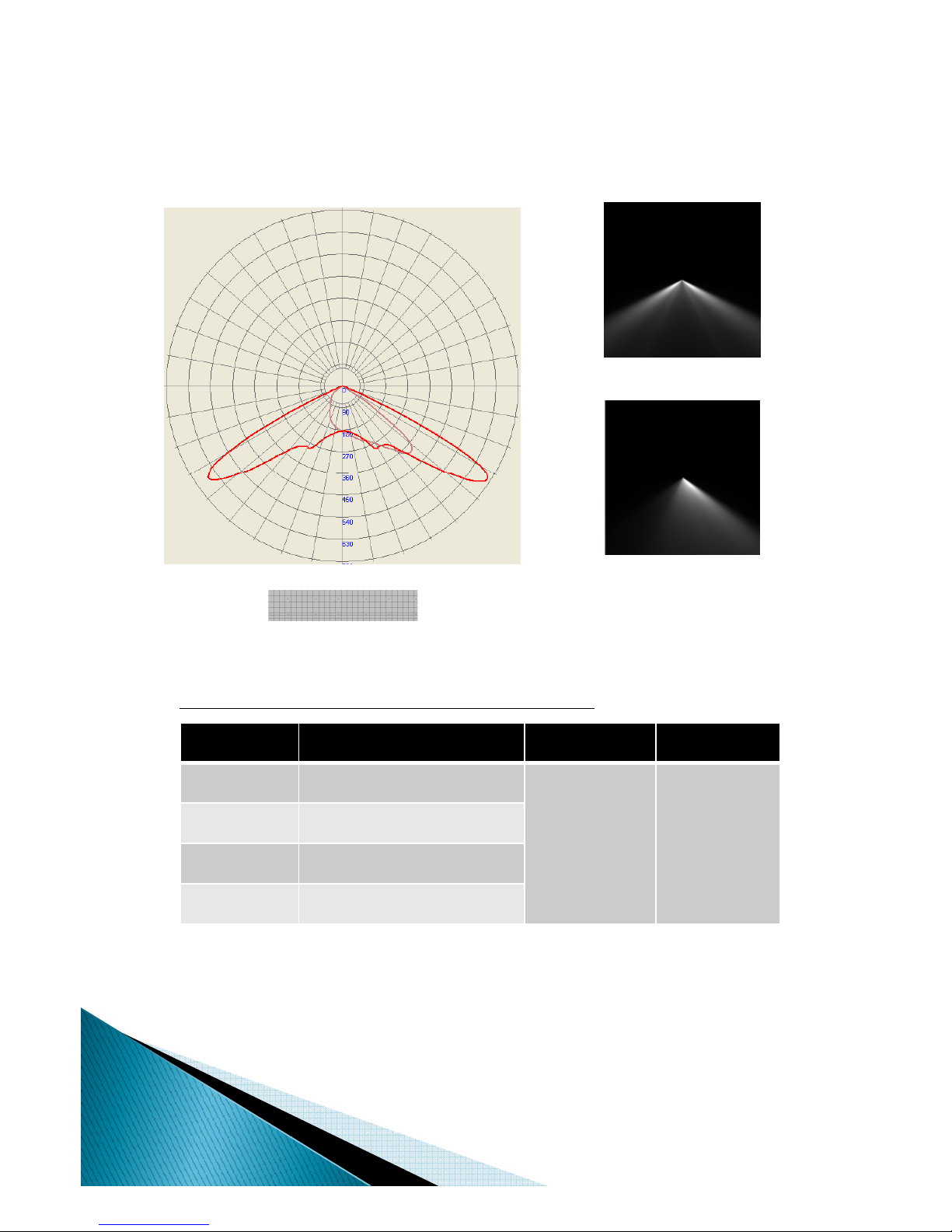
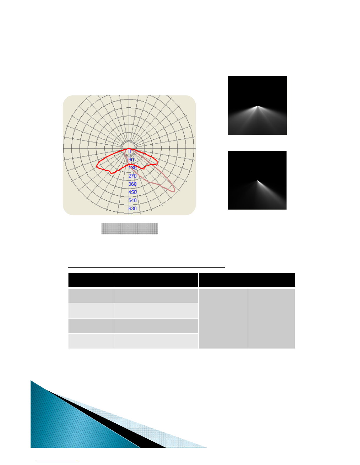
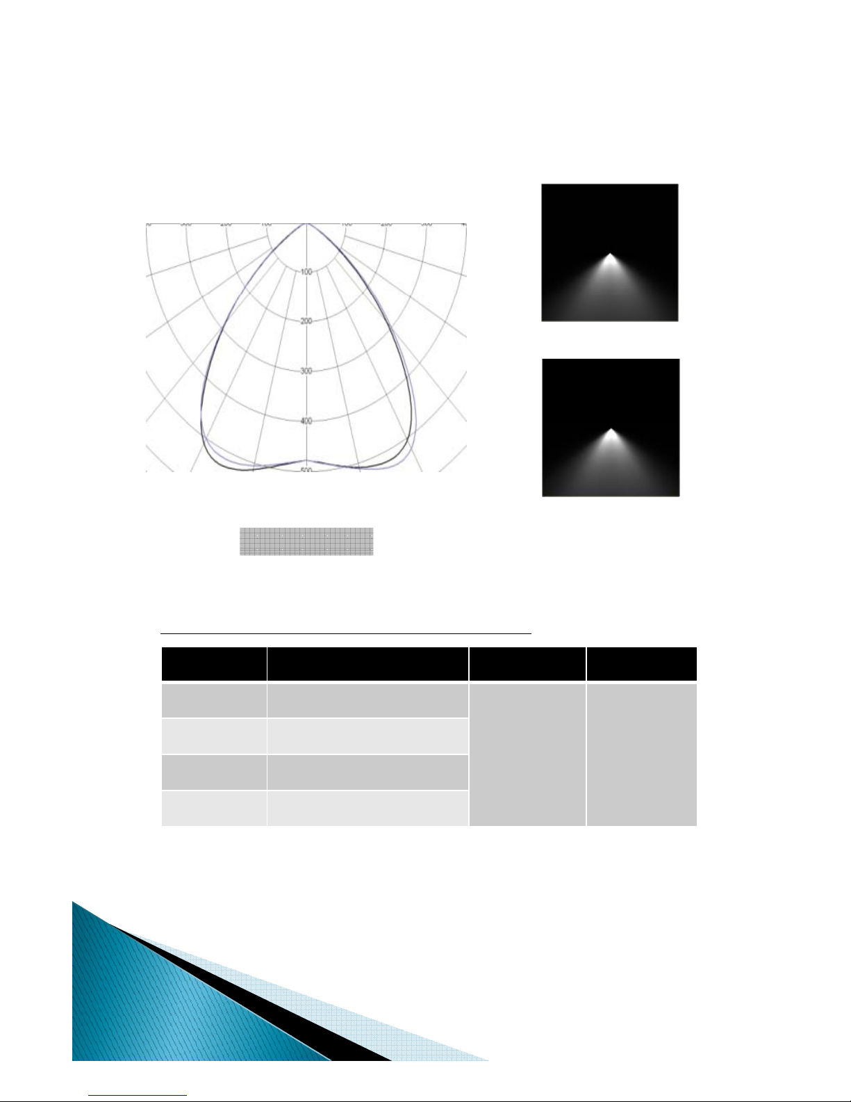
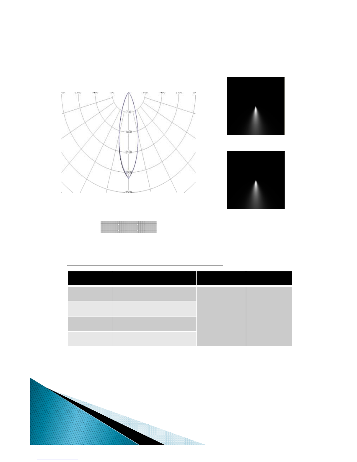
◈Models in the Appendix. A are measured to determine all values above with input current 500mA.
◈All values above are measured by the Integrating Sphere of LG Innotek with EC1000S / WT210.
◈All optic values are measured at 10±2sec. in the Integrating Sphere.
◈The Max. permitted input current putting into all models in the Appendix. A. is 650mA.
◈CRI values can have tolerances in the range of 3% caused by Measuring Instruments.
-2-

T III L
◆Module Specification with Type III lens and 6500K CCT(Base Model)
Ty
pe
III
L
ens
Horizontal view
Light Distribution
Vertical view
◆Beam Angle : H 135 °V 60°
If[mA] Luminance [lm] CCT[K] CRI
Table 1. Luminance values depending on Input Current
500 1000
6500 72
550 1055
600 1100
650(M )
1150
650(M
ax
)
1150
All Values @ Tc = 65ºC
* Values measured by KTR, 2011.5
* All values can have tolerances in the range of 5% caused by Measuring Instruments.
KTR : Korea Testing & Research Institute (Public Approval Institution)
-3-

TIIL
◆Module Specification with Type II lens and 6500K CCT
Ty
pe
II
L
ens
Horizontal view
Light Distribution
Vertical view
◆Beam Angle : H 160 °V 70 °
If[mA] Luminance [lm] CCT[K] CRI
Table 1. Luminance values depending on Input Current
500 900
6500 72
550 950
600 990
650(M )
1020
650(M
ax
)
1020
All Values @ Tc = 65ºC
* Values measured by KTR, 2011.5
* All values can have tolerances in the range of 5% caused by Measuring Instruments.
KTR : Korea Testing & Research Institute (Public Approval Institution)
-4-

T V(S 130
°
)L
◆Module Specification with Type V(Sq130°) lens and 6500K CCT
Ty
pe
V(S
q
130
°
)
L
ens
Horizontal view
Light Distribution
Vertical view
◆Beam Angle : H 130 °V 130 °
If[mA] Luminance [lm] CCT[K] CRI
Table 1. Luminance values depending on Input Current
500 1000
6500 72
550 1055
600 1100
650(M )
1150
650(M
ax
)
1150
All Values @ Tc = 65ºC
* Values measured by KTR, 2011.5
* All values can have tolerances in the range of 5% caused by Measuring Instruments.
KTR : Korea Testing & Research Institute (Public Approval Institution)
-5-

T V(130
°
)L
◆Module Specification with Type V(130°) lens and 6500K CCT
Ty
pe
V(130
°
)
L
ens
Horizontal view
Light Distribution
Vertical view
◆Beam Angle : H 130°V 130 °
If[mA] Luminance [lm] CCT[K] CRI
Table 1. Luminance values depending on Input Current
500 1000
6500 72
550 1055
600 1100
650(M )
1150
650(M
ax
)
1150
All Values @ Tc = 65ºC
* Values measured by KTR, 2011.5
* All values can have tolerances in the range of 5% caused by Measuring Instruments.
KTR : Korea Testing & Research Institute (Public Approval Institution)
-6-

◆Module Specification with Type V(115°) lens and 6500K CCT
TV(115
°
)L
Ty
pe
V(115
°
)
L
ens
Horizontal view
Light Distribution
Vertical view
◆Beam Angle : H 115°V 115 °
If[mA] Luminance [lm] CCT[K] CRI
Table 1. Luminance values depending on Input Current
500 1100
6500 72
550 1180
600 1250
650(M )
1300
650(M
ax
)
1300
All Values @ Tc = 65ºC
* Values measured by KTR, 2011.5
* All values can have tolerances in the range of 5% caused by Measuring Instruments.
KTR : Korea Testing & Research Institute (Public Approval Institution)
-7-

◆Module Specification with Type V(30°) lens and 6500K CCT
TV(30
°
)L
Ty
pe
V(30
°
)
L
ens
Horizontal view
Light Distribution
Vertical view
◆Beam Angle : H 30°V 30 °
If[mA] Luminance [lm] CCT[K] CRI
Table 1. Luminance values depending on Input Current
500 1100
6500 72
550 1180
600 1250
650(M )
1300
650(M
ax
)
1300
All Values @ Tc = 65ºC
* Values measured by KTR, 2011.5
* All values can have tolerances in the range of 5% caused by Measuring Instruments.
KTR : Korea Testing & Research Institute (Public Approval Institution)
-8-

◆Module Specification with Type V(20°) lens and 6500K CCT
TV(20
°
)L
Ty
pe
V(20
°
)
L
ens
Horizontal view
Light Distribution
Vertical view
◆Beam Angle : H 20°V 20 °
If[mA] Luminance [lm] CCT[K] CRI
Table 1. Luminance values depending on Input Current
500 1100
6500 72
550 1180
600 1250
650(M )
1300
650(M
ax
)
1300
All Values @ Tc = 65ºC
* Values measured by KTR, 2011.5
* All values can have tolerances in the range of 5% caused by Measuring Instruments.
KTR : Korea Testing & Research Institute (Public Approval Institution)
-9-

◆LED Module Installation
3. LED Module Instruction Manual
◈When the LED module with Type II or III lens is mounted on a heatsink or
luminaire, the connector way-out of the LED module should be oriented in a certain
direction due to its asymmetric light distribution. Refer to the Appendix D.
◈Combining the LED module with a heat-sink is very important for stable and normal
operation of the LED module. There should be no gap between a thermal pad attached
on the LED
module plate,
and the
heatsink
after
they are assembled
. Refer to Figure
8.
◆
Ci
on
the
LED
module
plate,
and
the
heatsink
after
they
are
assembled
.
Refer
to
Figure
8.
in Appendix C.
◈LED module should be tightly fixed on a heat-sink by fastening bolts.
◈The connector(male) should be correctly linked with another connector(female) from a
dedicated convertor. [ - : Black wire / + : Gray]
◆
C
aut
i
on
◈The LED module should not be operated by any unauthorized Power Supply Unit.
The LED module must be used only with certain power supplies recommended by
LG Innotek or a power which is satisfied for all the values in the Specification on Page 2.
◈Heatsink which takes the thermal energy from the LED module should be tightly
attached on the module so that the module temperature, especially at Tc, can keep the
condition lower than 70 ˚C.
◈A heat-sink combined with the LED module should not be directly mounted on the
perfectly insulated ceiling or wall since it is hard to radiate the heat caused by the LED
module. The heat from the LED module must disperse to the surroundings in order to
keep the module temperature(Tc) under 70˚C.
◈
The LED module should be stored in the range of temperature between
-
40
˚
C and 80
˚
C.
◈
The
LED
module
should
be
stored
in
the
range
of
temperature
between
40 C
and
80 C.
◈The connector or wires , coming from the module, should not be pulled by any forces.
It causes that the LED module might not be properly operated.
◈The LED module should not be struck by any physical impacts such as dropping the
module into the ground.
◈IP class of the module is IP67 which can protect against the affect of immersion under
the water in depth only between 15cm ~ 1m for half an hour.
◈Exceeding the operating current leads to an overload on the LED module. This may
result in a significant reduction in product lifetime or even destruction of the LED
module. The maximum permissible current is up to 650mA.
◈Do not touch the LED module on purpose during the operation with a Power Supply
- 10 -

4. Applications
-11-

5. Warranty
LG Innotek warrants the LED module for a period of five years from the date of sale to the
buyer when properly installed on a Heatsink or Luminaire and under normal conditions of use.
The buyer agrees to make all claims regarding defects or deficiencies in the LED module
according to the terms of LG Innotek
'
s official warranty Warranty claims should be made in
according
to
the
terms
of
LG
Innotek s
official
warranty
.
Warranty
claims
should
be
made
in
writing according to LG Innotek procedures.
Valid warranty claims must be made within the warranty period, 5 years, and submitted
within seven days of discovery of the damage or defect. Field labor, repair, dismantle, or
installation charges are NOT included with this warranty. Any unauthorized return, repair,
replacement or modification of the Module shall void this warranty. This warranty does not
cover any misapplication or misuse or installation in extremely hazardous or corrosive
environments. Contact LG Innotek (82-31-000-000/ @lginnotek.com) for complete
warranty language, exceptions, limitations, more details.
- 12 -

6. Ordering Information
Item Option Code
CCT
3000K WW
4000K NW
6500K CW
Lens
Type II (H:135ºC V:60ºC) A
Type III (H:135ºC V:60ºC) B
Type V (Square 130ºC) C
Type V (Circle 130ºC) D
Type V (Circle 115
º
C)
E
Type
V
(Circle
115 C)
E
Type V (Circle 30ºC) F
Type V (Circle 20ºC) G
Connector
JWPF, waterproof Connector JST Mfg. Co, Ltd. U
No connector - N
Cable Length
100mm each
LS cable. Co, Ltd.
10
200mm each 20
400mm each 40
Product Name CCT Lens Connector Cable Length
Eagle eye CW B U 10
Ex) LED Module with Type III lens, Connector, 100mm cable, 6500K PKG
Eagle eye-CW-B-U-10
*
Red Color : Not available (Developing now in progress)
Red
Color
:
Not
available
(Developing
now
in
progress)
- 13 -

Appendix. A. Model Information
1. Model Name
CCT Lens Model Name Remarks
Type II LLDMWW0-15K901A
Type III LRD01-11J4A
(LLDMWW0-15K902A) Base Model
6500K
Type V(Sq 130°)LLDMWW0-15K903A
Type V(130°)LLDMWW0-15K904A
Type V(115°)LLDMWW0-15K905A
Type V(30°)LLDMWW0-15K906A
Type V(20°)LLDMWW0-15K907A
2. Model Dimension
- 14 -

1. LED PKG Flux Characteristics
(
t
j
= 25ºC
)
Appendix. B. LED Package Properties
(
j
)
Color
CCT Range
Luminous Flux [lm] @ 350mA Typical CRI
Min Max
Cool White 5000K 8300K 122 75
2. LED PKG Characteristics
Characteristics Unit Typical Maximum
Thermal Resistance(Junction to Solder Point) ºC/W 6 75
Viewing Angle Degrees 125
Temperature Coefficient of voltage mV/ºC -2.1
ESD Classification (HBM per Mil-Std-883D) - Class 2
DC Forward Current mA - 1500
Reverse Voltage V - 5
Forward Voltage @ 350mA V 3.0 3.75
Forward Voltage @ 700mA V 3.2
Forward Voltage @ 1000mA V 3.3
LED Junction Temperature ºC - 150
3. LED PKG Characteristic Curve
Figure 1. Relative Luminous Flux vs. Current Figure 2. Electrical Characteristics (Tj = 25 ºC)
- 15 -

4. PKG Multi-Rank Mixing(M.R.M)
•
CCT
=
6530K
±
510K
To keep the value of CCT of the LED Module in the specified range, the PKG Rank enclosed
with red line in the Figure 9 should be mixed as shown in the Table2. Arrangement of the LED
PKG on the Metal PCB is recommended as shown Figure 10.
CCT
6530K
±
510K
Figure.3 Chromaticity Region for ANSI Cool White
PKG M.R.M P1 P1 P1 P1 P2 P2 P2 P2 P2 P2
PKG
A
1A
1B
1B
1A
1S
1T
1B
1A
1C
1D
Table1. The Order of Priority for PKG M.R.M
PKG
A
1A
1B
1B
1A
1S
1T
1B
1A
1C
1D
PKG B 1D 1C 1D 1C 1U 1R 1U 1T 1R 1S
P1 : The First Order of Priority for PKG M.R.M
P2 : The Second Order of Priority for PKG M.R.M
Figure.4 PKG Arrangement
- 16 -

1
.
Overview
Appendix. C. Thermal Management
1
.
Overview
•Since heat-sink design for the module would affect lifetime and performance of the module,
a heat-sink or luminaire should be designed with thermal considerations to smoothly
dissipate the thermal energy to the ambient.
•End product with the LED module should be designed in a manner which minimizes
the thermal resistance from the solder point to ambient in order to optimize the LED module
life and its optical characteristics
2. Heat sink Design guide
•The lifetime of the LED module cannot be guaranteed if operated without a heat-sink.
The heat-sink should be coupled with the module for thermal management as shown in Figure 9.
•Design of the heat-sink is one of the main factor which determines lifetime and performance
of the module. Hest-sink should be designed to keep the module temperature, Tc, under 70°C.
•Recommended material for the heat-sink is metals such as
,
Aluminum whose conductivit
y
is
,y
relatively higher and cheaper than other materials. In addition, surface treatment of the
heat-sink is important to increase the rate of heat-transfer. Powder coating and Anodizing
might be a good solution for the surface treatment of the heat-sink.
Figure.5 Assembly between Heat-sink(Al) and LED Module
- 17 -

3
.
Case
Temperature
&
Junction
Temperature
3
.
Case
Temperature
&
Junction
Temperature
•Junction Temperature(Tj)
Definition of Junction Temperature(Tj) is internal temperature of a chip
at which temperature has the highest value.
Since
it
is
hard
to
measure
Junction
Temperature(Tj)
at
firsthand
the
value
of
the
Tj
Since
it
is
hard
to
measure
Junction
Temperature(Tj)
at
firsthand
,
the
value
of
the
Tj
can be assumed by the equation shown in Figure.11 on the next page.
•Case Temperature (Tc):
Case Temperature(Tc) is the temperature at the center point of the module plate remarked
in Figure 10. It shows how to measure Tc.
*Case Temperature(Tc) should be lower than 70ºC while the LED module is operating.
Thermal paste
Thermal
paste
Case temperature (Tc)
Thermocouple
Figure.6 Module Plate (bottom view)
- 18 -
Table of contents
Popular Lighting Equipment manuals by other brands

Cameo
Cameo Q SPOT 15W user manual

Chauvet
Chauvet COLORstrip Mini FX user manual

Vision & Control
Vision & Control A-DIF-120x240-R633-SL Instructions for use

Dale Tiffany
Dale Tiffany AA12093 Assembly instructions

Sycamore
Sycamore Sirius SY7690 installation instructions

Elation
Elation Design LED 60 Strip II WA Technical specifications