LG 42PC35 User manual

PLASMA TV
SERVICE MANUAL
CAUTION
BEFORE SERVICING THE CHASSIS,
READ THE SAFETY PRECAUTIONS IN THIS MANUAL.
CHASSIS : PD73A
MODEL : 42PC35 42PC35-ZC
website:htt ://biz.LGservice.com
Internal Use Only

- 2 - LGE Internal Use OnlyCopyright©2007 LG Electronics. Inc. All right reserved.
Only or training and service purposes
CONTENTS
SAFETY PRECAUTIONS ....................................................................................3
SPECIFICATIONS ................................................................................................4
ADJUSTMENT INSTRUCTIONS .........................................................................6
TROUBLE SHOOTING GUIDE..........................................................................19
BLOCK DIAGRAM.............................................................................................28
EXPLODED IEW..............................................................................................30
EXPLODED IEW PARTS LIST ........................................................................31
REPLACEMENT PARTS LIST...........................................................................32
SCHEMATIC DIAGRAM.........................................................................................
PRINTED CIRCUIT DIAGRAM ..............................................................................

- 3 - LGE Internal Use OnlyCopyright©2007 LG Electronics. Inc. All right reserved.
Only or training and service purposes
SAFETY PRECAUTIONS
Many electrical and mechanical parts in this chassis have special sa ety-related characteristics. These parts are identi ied by in the
Schematic Diagram and Replacement Parts List.
It is essential that these special sa ety parts should be replaced with the same components as recommended in this manual to prevent
X-RADIATION, Shock, Fire, or other Hazards.
Do not modi y the original design without permission o manu acturer.
General Guidance
An isolation Transformer should always be used during the
servicing o a receiver whose chassis is not isolated rom the AC
power line. Use a trans ormer o adequate power rating as this
protects the technician rom accidents resulting in personal injury
rom electrical shocks.
It will also protect the receiver and it's components rom being
damaged by accidental shorts o the circuitry that may be
inadvertently introduced during the service operation.
I any use (or Fusible Resistor) in this monitor is blown, replace it
with the speci ied.
When replacing a high wattage resistor (Oxide Metal Film Resistor,
over 1W), keep the resistor 10mm away rom PCB.
Keep wires away rom high voltage or high temperature parts.
Due to high vacuum and large sur ace area o picture tube,
extreme care should be used in handling the Picture Tube.
Do not li t the Picture tube by it's Neck.
Leakage Current Cold Check(Antenna Cold Check)
With the instrument AC plug removed rom AC source, connect an
electrical jumper across the two AC plug prongs. Place the AC
switch in the on position, connect one lead o ohm-meter to the AC
plug prongs tied together and touch other ohm-meter lead in turn to
each exposed metallic parts such as antenna terminals, phone
jacks, etc.
I the exposed metallic part has a return path to the chassis, the
measured resistance should be between 1MΩ and 5.2MΩ.
When the exposed metal has no return path to the chassis the
reading must be in inite.
An other abnormality exists that must be corrected be ore the
receiver is returned to the customer.
Leakage Current Hot Check (See below Figure)
Plug the AC cord directly into the AC outlet.
Do not use a line Isolation Transformer during this check.
Connect 1.5K/10watt resistor in parallel with a 0.15uF capacitor
between a known good earth ground (Water Pipe, Conduit, etc.)
and the exposed metallic parts.
Measure the AC voltage across the resistor using AC voltmeter
with 1000 ohms/volt or more sensitivity.
Reverse plug the AC cord into the AC outlet and repeat AC voltage
measurements or each exposed metallic part. Any voltage
measured must not exceed 0.75 volt RMS which is corresponds to
0.5mA.
In case any measurement is out o the limits speci ied, there is
possibility o shock hazard and the set must be checked and
repaired be ore it is returned to the customer.
Leakage Current Hot Check circuit
1.5 Kohm/10W
To Instrument's
exposed
METALLIC PARTS
Good Earth Ground
such as WATER PIPE,
CONDUIT etc.
AC Volt-meter
IMPORTANT SAFETY NOTICE
0.15uF

- 4 - LGE Internal Use OnlyCopyright©2007 LG Electronics. Inc. All right reserved.
Only or training and service purposes
SPECIFICATIONS
NOTE : Speci ications and others are subject to change without notice or improvement
.
VApplication Range
This spec is applied to the 42” PLASMA TV used PD73A Chassis.
V Specification
Each part is tested as below without special appointment.
1) Temperature : 25±5°C (77±9°F), CST : 40±5
2) Relative Humidity: 65±10%
3) Power Voltage: Standard Input voltage (100-240V~, 50/60Hz)
* Standard Voltage o each product is marked by models.
4) Speci ication and per ormance o each parts are ollowed each drawing and speci ication by part number in accordance with SBOM.
5) The receiver must be operated or about 20 minutes prior to the adjustment.
VTest Method
1) Per ormance : LGE TV test method ollowed.
2) Demanded other speci ication
Sa ety : CE, IEC speci ication
EMC : CE, IEC
VGeneral Specification
1. Module Specification ( 42” XGA MODULE )
Display Screen Device
Aspect Ratio
PDP Module
Operating Environment
Storage Environment
Input Voltage
1
2
3
4
5
6
No Item Speci ication Remark
42” Wide Color Display Module
16:9
PDP42X4A,
RGB Closed Type, Film Filter
1)Temp. : 0~40deg
2)Humidity : 20~80%
3)Temp. : -20~60deg
4)Humidity : 10~90%
100-240V~, 50/60Hz
Plasma Display Panel
LGE SPEC.
Maker LG
Chassis
PD73A 42PC35
UK, German, Italy, France, Sweden, Finland, Spain,
Netherlands, Belgium, Luxemburg, Greece, Denmark,
Czech, Austria, Poland, Portugal, Norway, Rumania,
Hungary , Bulgaria, Croatia, Serbia, Swiss, Slovenia, Russia
LG
Model Name Market Brand Remark
42PC35
Sa ety : IEC/EN60065
EMI : EN55013
EMS : EN55020
UK, German, Italy, France, Sweden, Finland,
Spain, Netherlands, Belgium, Luxemburg,
Greece, Denmark, Czech, Austria, Poland,
Portugal, Norway, Rumania, Hungary , Bulgaria,
Croatia, Serbia, Swiss, Slovenia, Russia
Model ApplianceMarket
TEST
Remark

- 5 - LGE Internal Use OnlyCopyright©2007 LG Electronics. Inc. All right reserved.
Only or training and service purposes
2. Model General Specification
Market
Broadcasting system
Receiving system
Scart Jack (2EA)
Video Input (1EA)
S-Video Input (1EA)
Component Input (1EA)
RGB Input(1EA)
HDMI Input(2EA)
Audio Input (3EA)
1
2
3
4
5
6
7
8
9
10
No Item Speci ication Remark
UK, German, Italy, France, Sweden, Finland, Spain,
Netherlands, Belgium, Luxemburg, Greece,
Denmark, Czech, Austria
Poland, Portugal, Norway, Rumania, Hungary ,
Bulgaria, Croatia, Serbia, Swiss, Slovenia, Russia
1) PAL-BG
2) PAL-DK
3) PAL-I,I’
4) DVB-T(ID TV)
5) SECAM-L/L’
Analog : Upper Heterodyne
Digital : COFDM
PAL, SECAM
PAL, SECAM, NTSC
PAL, SECAM, NTSC
Y/Cb/Cr, Y/Pb/Pr
RGB-PC
HDMI-DTV & SOUND
PC Audio, Component, AV
Analog Only
4 System : PAL, SECAM, NTSC, PAL60
L/R Input

- 6 - LGE Internal Use OnlyCopyright©2007 LG Electronics. Inc. All right reserved.
Only or training and service purposes
ADJUSTMENT INSTRUCTIONS
1. Application Object
These instructions are applied to all o the 42” PLASMA TV,
PD73A Chassis.
2. Note
(1) Because this is not a hot chassis, it is not necessary to use
an isolation trans ormer. However, the use o isolation
trans ormer will help protect test instrument.
(2) Adjustment must be done in the correct order.
(3) The adjustment must be per ormed in the circumstance o
25±5°C o temperature and 65±10% o relative humidity i
there is no speci ic designation.
(4) The input voltage o the receiver must keep 100-240V~,
50/60Hz.
(5) The receiver must be operated or about 15 minutes prior
to the adjustment.
OA ter RGB Full white HEAT-RUN Mode, the receiver must
be operated prior to adjustment.
OEnter into HEAT-RUN MODE
1) Press the POWER ON KEY on R/C or adjustment.
2) OSD display and screen display PATTERN MODE.
[Set is activated HEAT-RUN without signal generator in
this mode.
[Single color pattern(RED/BLUE/GREEN) o HEAT-RUN
mode uses to check PANEL.
3. Channel memory Setting Method
: You can set channel memory by R/C or adjustment.
( Recovery the channel memory by adjust R/C)
1) Press ADJ key on R/C or adjustment.
2) Press VOL + key on “Channel Recover”.
4. PCMCIA CARD Checking Method
: You must adjust DTV 29 Channel and insert PCMCIA CARD
to socket.
1) I PCMCIA CARD works normally, normal signals display
on screen.
But it works abnormally, “No CA module” words display on
screen.
5. POWER PCB Assy oltage
Adjustments (Va, Vs Voltage adjustments)
5-1. Test Equipment : D.M.M. 1EA
5-2.Connection Diagram for Measuring
: re er to Fig.1
5-3. Adjustment Method
(1) a Adjustment
1) A ter receiving 100% Full White Pattern, HEAT RUN.
2) Connect + terminal o D.M.M to Va pin o P812, connect
- terminal to GND pin o P812.
3) A ter turning VR901, voltage o D.M.M adjustment as
same as Va voltage which on label o panel right/top.
(Deviation; ±0.5V)
(2) s Adjustment
1) Connect + terminal o D.M.M to Vs pin o P812, connect
– terminal to GND pin o P812.
2) A ter turning VR951, voltage o D.M.M adjustment as
same as Va voltage which on label o panel right/top.
(Deviation; ±0.5V)
I you turn on a still screen more than 20 minutes (Especially
Digital pattern, Cross Hatch Pattern), an a terimage may occur
in the black level part o the screen.
Each PCB assembly must be checked by check JIG set.
(Because power PCB Assembly damages to PDP Module,
especially be care ul)
(Fig. 1) Connection diagram o power adjustment or measuring
<42” EAY32808901>

- 7 - LGE Internal Use OnlyCopyright©2007 LG Electronics. Inc. All right reserved.
Only or training and service purposes
6. EDID (The Extended Display
Identification Data)/ DDC (Display
Data Channel) download
6-1. Required Test Equipment
1) Adjusting PC with S/W or writing EDID Data.(S/W : EDID
TESTER Ver.2.5)
2) A Jig or EDID Download
3) Cable : Serial(9Pin or USB) to D-sub 15Pin cable, D-sub
15Pin cable, DVI to HDMI cable
6-2. Setting of device
6-3. Preparation for Adjustment
1) As above Fig. 2, Connect the Set, EDID Download Jig, PC
& Cable.
2) Turn on the PC & EDID Download Jig. And Execute the
S/W : EDID TESTER Ver,2.5.
3) Set up S/W option.
Repeat Number : 5
Device Address : A0
PageByte : 8
4) Power on the Set.
6-4. Sequence of Adjustment
- EDID Download
1) Init the data.
2) Load the EDID data.(Open File).
[Analog ile] ( or RGB)
[Digital ile] ( or HDMI)
3) Set the S/W as below.
4) Push the “Write Data & Veri y”button. And con irm “Yes”.
5) I the writing is inished, you will see the “OK” message.
6) I TV has two HDMI, you must download two times or
each HDMI.
(Fig. 2) Connection Diagram o DDC download
Open FileOpen File

- 8 - LGE Internal Use OnlyCopyright©2007 LG Electronics. Inc. All right reserved.
Only or training and service purposes
- EDID DATA
1) Analog RGB.
=> Detail EDID Options are below([1], [2], [3],[4], [5])
1. [1]-Product ID
2. [2]-Serial No : Controlled on production line
3. [3]-Month, Year : Controlled on production line
ex) Week : '03' => '03'
Year : '2006' => '10'
4. [4]-Model Name(Hex):
5. [5]-Checksum : Changeable by total EDID data
2) HDMI1.
=> Detail EDID Options are below([1], [2], [3],[4], [5])
1. [1]-Product ID
2. [2]-Serial No : Controlled on production line
3. [3]-Month, Year : Controlled on production line
ex) Week : '03' => '03'
Year : '2006' => '10'
4. [4]-Model Name(Hex):
5. [5]-Checksum : Changeable by total EDID data
3) HDMI2.
=> Detail EDID Options are below([1], [2], [3],[4], [5])
* Please re er HDMI1
Model
Name
42PC35
Product ID
Product ID EDID table
D99C
Hex
9CD9
40153
Model Name
42PC35
Hex Data
00 00 00 FC 00 34 32 50 43 33 35 0A 20 20 20 20 20 20
12
3
4
5
12
3
4
5
5
Model
Name
42PC35
Product ID
Product ID EDID table
DA9C
Hex
9CDA
40154
Model Name
42PC35
Hex Data
00 00 00 FC 00 34 32 50 43 33 35 0A 20 20 20 20 20 20
12
3
4
5
5

- 9 - LGE Internal Use OnlyCopyright©2007 LG Electronics. Inc. All right reserved.
Only or training and service purposes
7. ADC Calibration
8. Auto A (C BS) Color Balance
8-1. Requirement
VThis AV color balance adjustment should be per ormed
be ore white Balance Adjustment.
8-2. Required Equipment
1) Remote controller or adjustment.
2) MSPG-925FS Pattern Generator (Which has Video Signal:
7 Color Bar Pattern shown in Fig. 3).
- Model: 202 / Pattern: 65 EC and FC model use PAL-
BGDHI. (composite signal)
8-3. Method of Auto A (C BS) Color Balance
1) Input the Video signal: 7 color Bar signal into AV3.
2) Set the PSM to Dynamic mode in the Picture menu.
3) Press IN-STAR key on R/C or adjustment.
4) Press the G(Vol. +) key operate to set, then it becomes
automatically.
5) Auto-RGB OK means completed adjustment.
9. Adjustment of Component
9-1. Requirement
VThis AV color balance adjustment should be per ormed
be ore white Balance Adjustment.
9-2. Required Equipment
1) Remote controller or adjustment.
2) MSPG-925FS Pattern Generator (Which has Video Signal:
7 Color Bar Pattern shown in Fig. 4).
- Model: 215 / Pattern: 65
9-3. Method of Auto Component Color Balance
1) Input the Component 720p/50Hz 7 Color Bar(MSPG-925FS
model:215, pattern:65) signal into Component.
2) Set the PSM to Dynamic mode in the Picture menu.
3) Press IN-STAR key on R/C or adjustment.
4) Press the G(Vol. +) key operate to set, then it becomes
automatically.
5) Auto-RGB OK means completed adjustment.
10. Adjustment of RGB
10-1. Requirement
VThis AV color balance adjustment should be per ormed
be ore white Balance Adjustment.
10-2. Required Equipment
1) Remote controller or adjustment.
2) MSPG-925FS Pattern Generator (Which has Video Signal:
7 Color Bar Pattern shown in Fig. 5).
- Model: 215 / Pattern: 65
10-3. Method of Auto RGB Color Balance
1) Input the PC 1024x768 @ 60Hz 7 color bar (MSPG-925FS,
Model:3, Pattern: 65) into RGB. (using D-sub to D-sub
cable)
2) Set the PSM to Dynamic mode in the Picture menu.
3) Press IN-STAR key on R/C or adjustment.
4) Press the G(Vol. +) key operate to set, then it becomes
automatically.
5) Auto-RGB OK means completed adjustment.
MSPG925FS
Component RGB-PCRF/AV/S-VIDEOADC
Model : 3
(1024*768 60Hz)
Pattern : 65
7 Color Bar
Model:215(720P)
Pattern : 65
* 720P/50Hz
7 Color Bar
PAL
INPUT SELECT AV3
Model : 202
(PAL-BGDHI)
Pattern : 65
* PAL 7 Color Bar
- System control RS-232 Host should be “PC“ or adjustment.
- Be ore AV ADC Calibration, execute the “Panel size selection“
(Fig. 4) Color bar Test Pattern
(Fig. 3) Color Balance signal
(Fig. 5) Color bar Test Pattern

- 10 - LGE Internal Use OnlyCopyright©2007 LG Electronics. Inc. All right reserved.
Only or training and service purposes
11. Adjustment of White Balance
11-1. Requirement
1) Be ore adjusting White-balance , the AV ADC should be
done.
2) I ADC status were “NG”, Need to ADC adjustment.
11-2. Required Equipment
1) Remote controller or adjustment.
2) Color Analyzer.( CA-1000,CA-100,100+,CA-210 or same
product ) : CH10(PDP)
* Please adjust CA-210, CA-100+ by CS-1000 before
measuring.
3) Auto W/B adjustment instrument.(only or Auto adjustment)
4) AV Pattern Generator.
W Color temperature standards according to CSM and Module.
W
CS-1000/CA-100+/CA-210(CH10) White balance adjustment
coordinate and color temperature.
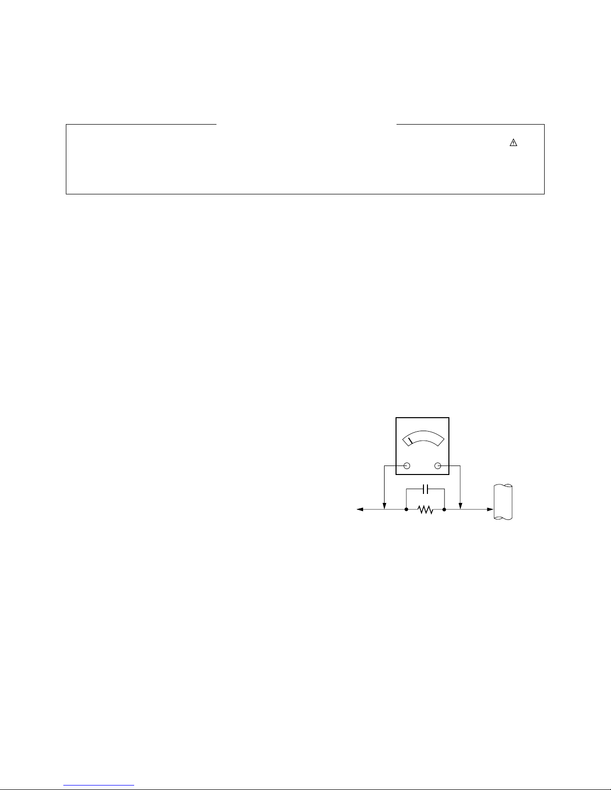
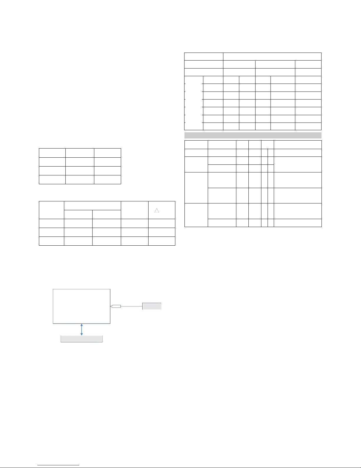
11-3. Connection Picture of the Measuring
Instrument(On Automatic control)
V Inside PATTERN is used when W/B is controlled. Connect
to auto controller or push control R/C IN-START -> Enter
the mode o White-Balance, the pattern will come out.
V Auto-control inter ace and directions
1. Adjust in the place where the in lux o light like loodlight
around is blocked.(illumination is less than 10ux)
2. Measure and adjust a ter sticking the Color Analyzer(CA-
100+, CA210) to the side o the module.
3. Aging time
1) A ter aging start, keep the power on(no suspension o
poewr supply) and heat-run over 15minutes.
2) Keep white pattern using inside pattern.
V Auto adjustment Map(RS-232C)
- Baud : 115200bps, RS232 Host : PC, Echo : none
12. Adjustment of White Balance
(Manual white Balance)
V One o R Gain/ G Gain/ B Gain should be kept on 80, and
others are controlled lowering rom 80
(1) ‘power on’ o the control R/C, set heat run to white by
pressing and heat run over 15 minutes. (Set: RS-232 Host:
PC, Baud Rate: 115200bps, Download: Cortez)
(2) Zero Calibrate CA-100+, and stick the sensor to the center
o PDP module sur ace when you adjust.
(3) Double click In-start key on Controlling R/C and get in
‘white balance’.
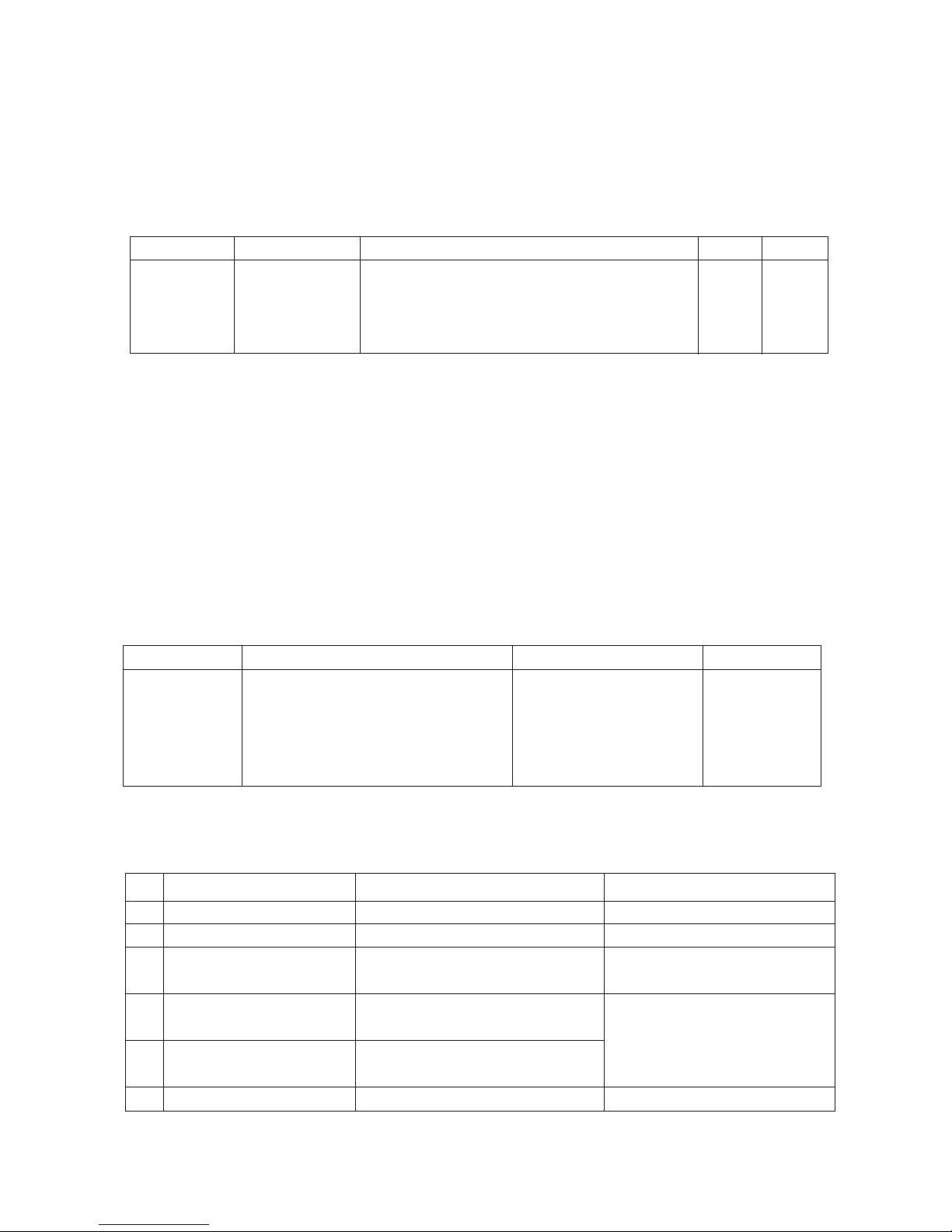
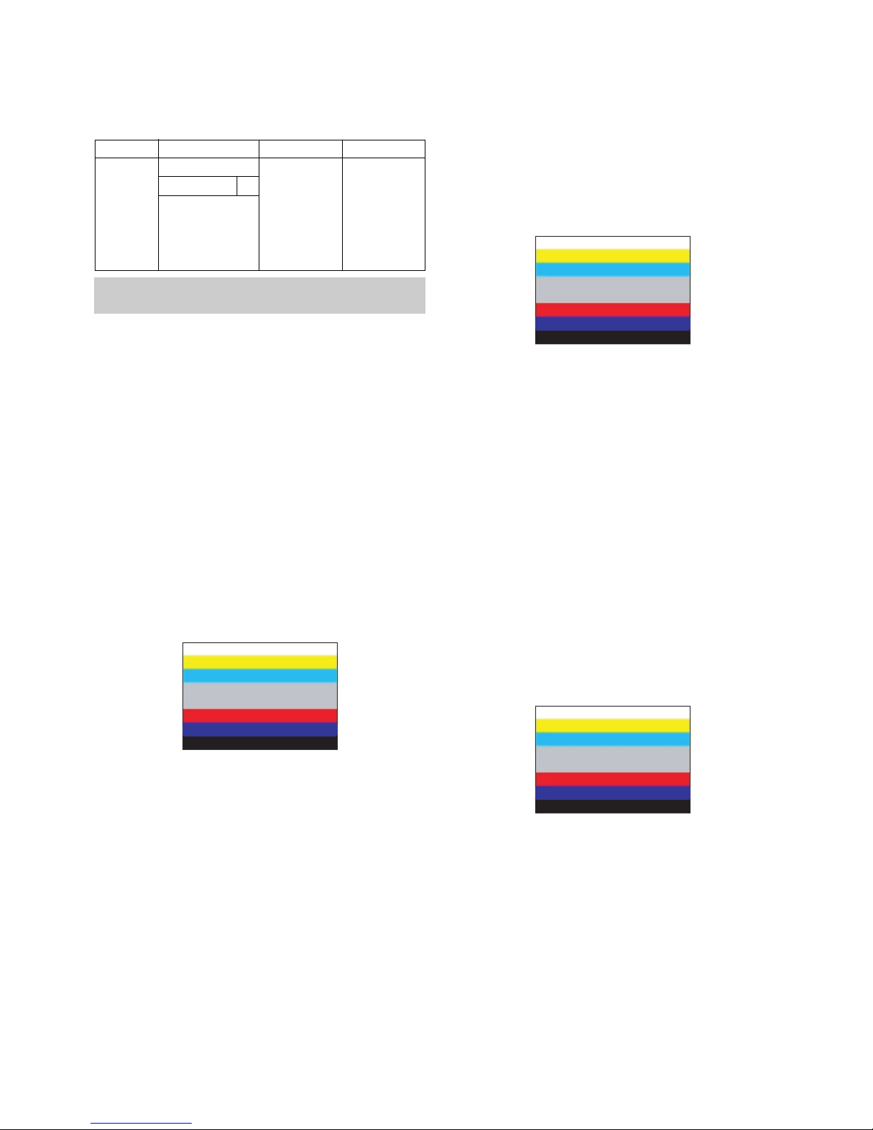
(4) Set test-pattern on and display inside pattern. Control is
carried out on three color temperature, COOL, MEDIUM,
WARM. (Control is carried out three times.)
(5) When the R/G/B GAIN is 80 on OSD, it is the FULL
DYNAMIC Range o the Module. In order to control white
balance without the saturation o FULL DYNAMIC Range
and DATA, one o R Gain / G Gain / B Gain should be kept
on 80, and other two is controlled lowering rom 80.
* Color Temperature: Cool, Medium, Warm
(1) When R GAIN is set to 80
- Control G GAIN and B GAIN by lowering rom 80.
(2) When B GAIN is set to 80
- Control R GAIN and G GAIN by lowering rom 80.
(3) When G GAIN is set to 80
- Control R GAIN and B GAIN by lowering rom 80.
One o R Gain / G Gain / B Gain should be kept on 80, and
adjust other two lower than 80.
(When R/G/B GAIN are all 80, it is the FULL DYNAMIC
Range o Module)
(Fig. 6) Auto AV(CVBS) Color Balance Test Pattern
Full White Pattern
RS-232C Communication
CA-210
Color
ANALYZER
TYPE : CA-210
Color Coordinate
xy
0.283±0.002
0.293±0.002
0.329±0.00
2
11000K
9300K
6500K
0.000
0.000
0.003
0.276±0.002
0.285±0.002
0.313±0.00
2
COOL
MEDIUM
WARM
Mode Temp uv
PLASMA Remark
11000K
9300K
6500K
Cool
Normal
Warm
CSM
ADC adjust
Data Read
De ault Write
Enter
Adjust Mode
ADC adjust
ADC Parameter
Digital Data
ADC Parameter
(Average)
Adjustment
Con irmation
Adjust ‘Mode In’
Adjust ‘Mode O ’
NO Item Remark
CMD1 CMD2
Data 0
A
A
A
A
A
A
A
D
D
D
D
D
D
D
0
0
0
0
9
0
0
1
2
3
4
9
0
9
Trans er 18Byte
(Input resolution Data)
To check ADC Adjusment
on Assembly line
When transger the ‘Mode
In’, Carry the command.
- Caution : Using ‘power on’ button’ o the control R/C, power in TV.
Type
Baud Rate
115200
Index
R Gain
G Gain
B Gain
R O set
G O set
B O set
Data bit
8
Cmd1 Cmd2
ja
jb
jc
jd
je
j
Stop bit
1
Parity
NONE
PD73A
Protocol
Setting
Data Min Value
00(00)
00(00)
00(00)
00(00)
00(00)
00(00)
Max Value
128(80)
128(80)
128(80)
128(80)
128(80)
128(80)

- 11 - LGE Internal Use OnlyCopyright©2007 LG Electronics. Inc. All right reserved.
Only or training and service purposes
13.
Default alue in Adjustment mode
13-1. Auto Color Balance
13-2. Write Balance
14. EEPROM Data Write
(Serial No D/L)
14-1. Signal TABLE
CMD : A0h
LENGTH : 85~94h (1~16 bytes)
ADH : E2PROM Sub Address high (00~1F)
ADL : E2PROM Sub Address low (00~FF)
Data : Write data
CS :
CMD + LENGTH + ADH + ADL + Data_1 + ... + Data_n
Delay : 20ms
14-2. Command Set
* Description
FOS De ault write : <7mode data> write
Vtotal, V_Frequency, Sync_Polarity, Htotal, Hstart, Vstart, 0, Phase
Data write : Model Name and Serial Number write in EEPROM,.
14-3. Method & Notice
(1) Serial number D/L is using o scan equipment.
(2) Setting o scan equipment operated by Manu acturing
Technology Group.
(3) Serial number D/L must be con ormed when it is produced
in production line, because serial number D/L is mandatory
by D-book 4.0.
15. Set Information(Serial No& Model name)
15-1.
Setting up like bottom figure
(After setting white balance, this is set)
(Setting: Press ADJ Key in the Adjust remocon)
(1) Select “System Control 2” by using D / E(CH+/-) key, and
press V (ENTER) Using Adjust remocon, RS-232 Host &
Baud Rate & Download value change)
15-2. Push the menu button in DT mode.
(1) Select the STATION-> Diagno stics -> To set.
CMD
LENGTH
ADH ADL
DATA_1 DATA_n
... CS DELAY
No
1
EEPROM WRITE
A0h 84h+n n-byted Write
(n=1~16)
Adjust mode CMD(hex) LENGTH(hex) Description
(Fig. 7) De ault on OSD
<Component> <RGB>
<AV>
(Fig. 8) De ault on OSD
Model
Name
42PC35
Tool
Option1
2176 1697 0 14 2 1 192
Tool
Option2
Area
Option
Option1 Option2 Option3 Option4

- 12 - LGE Internal Use OnlyCopyright©2007 LG Electronics. Inc. All right reserved.
Only or training and service purposes
(2) Check the Serial Number.
16. Input the Shipping Option Data
1) Push the IN-START key in a Adjust Remocon.
2) Input the Option Number that was speci ied in the BOM, into
the Shipping area.
3) The work is inished, Push VKey.
17. CORTEZ Download
17-1. CORTEZ Download By LGIDS
(1) Installation of the LGIDS
1) Extract to older IDS_Setup.ZIP.
2) Install LGIDS-1
1. A ter Click the ‘NEXT’ icon, Installation is inished.
3) Install LGIDS-2
1. You can ind the ICON on C:\Program Files\LGIDS.
(2) Download hex file
1) Prepare a Batch File(*.txt), RAM File(*.hex) on
C:\Program Files\LGIDS\ iles.
* In the TEXT FILE
2) Connect RS232 cable and turn on the power.
(Use the general RS-232C Serial Cable)

- 13 - LGE Internal Use OnlyCopyright©2007 LG Electronics. Inc. All right reserved.
Only or training and service purposes
3) Execute the LGIDS Program - 1
1. Check a ‘PDP’ & ‘Hurricane’ on the ‘Model’ MENU
*
I your connection is ‘NG’, then set your PORT(COM1,2,3...)
correctly.
4) SVC MENU Setting or CORTEZ DOWNLOAD.
case 1. Press the ‘tilt’ button on the Adjustment Remote
Control.
case 2. Press the ‘ADJ’ button
1) Press the ‘System Control 2’ menu
2) Enter the ‘GProbe’ on the ‘RS-232Host menu’
3) Enter ‘115200bps’ on the ‘Baud Rate menu’
4) Enter the ‘Cortez’ on the ‘Download menu’
* I you don’t have a Adjustment Remote Control
‘Menu’ button on the Remote Control + ‘Menu’ button on
the Local Key during 7~8sec
A ter Change a mode, you can see ‘GPROBE MODE’
5) Execute the LGIDS Program - 2
1. Open a Batch ile, RAM ile and Flash ile.
6) Execute the LGIDS Program - 3
7) Wait the inal message.
1. A ter DOWNLOAD, Turn o the TV a ter download -> Turn
on.

- 14 - LGE Internal Use OnlyCopyright©2007 LG Electronics. Inc. All right reserved.
Only or training and service purposes
17-2. CORTEZ Download By GProbe 5
(1) Installation of the GProbe 5
1) Extract to older GProbe5.0.0.15_S0006_EXE_09A.ZIP.
2) Install GProbe5.0.0.15.EXE - 1.
3) Install GProbe5.0.0.15.EXE - 2.
4) Install GProbe5.0.0.15.EXE - 3.
CLICK
CLICK

- 15 - LGE Internal Use OnlyCopyright©2007 LG Electronics. Inc. All right reserved.
Only or training and service purposes
5) Install GProbe5.0.0.15.EXE - 4.
(2) Download hex file using GProbe
1) Prepare a ‘*.hex‘, ‘isp_16_ext.hex‘, ‘*.txt‘ in the same older.
* In the TEXT FILE
2) Connect TV set and PC by using RS232 cable.
3) SVC MENU Setting or CORTEZ DOWNLOAD.
case 1. Press the ‘tilt’ button on the Adjustment Remote Control.
case 2. Press the ‘ADJ’ button.
1) Press the ‘System Control 2’ menu
2) Enter the ‘GProbe’ on the ‘RS-232Host menu’
3) Enter ‘115200bps’ on the ‘Baud Rate menu’
4) Enter the ‘Cortez’ on the ‘Download menu’
* I you don’t have a Adjustment Remote Control ‘Menu’
button on the Remote Control + ‘Menu’ button on the
Local Key during 7~8sec.
4) Execute the GProbe Program.
5) Open the batch ile - 1.
1. Click the ‘Commands’.
CLICK

- 16 - LGE Internal Use OnlyCopyright©2007 LG Electronics. Inc. All right reserved.
Only or training and service purposes
6) Open the batch ile - 1.
1. Click the ‘Commands’.
7) Open the batch ile - 2
1. Click ‘Bach’ in the ‘Commands’ menu & express the
‘...’ icon (It’s marked by the red check).
8) Open the batch ile - 3.
1. Choose the text ile.
9) It takes 300sec ~ 360sec, Wait the inal message.
1. Turn o the TV a ter download -> Turn on.
18. Insert the ‘TOOL OPTION’ &
SERIAL NUMBER
V When you change a Main Ass’y, you should insert the TV
SET’s original Serial Number & MODEL NAME. It is the
way how to insert original number.
18-1. Insert the ‘Tool Option’
1) Insert ‘2176’ on ‘Tool Option1’, ‘1697’ on ‘Tool Option2’ or
42PC35 Press the ‘ENTER’ Button.
1. Be ore change the ‘Tool Option’, you should check
the White Balance Value.
2. Because change the ‘Tool Option’, the White Balance
Value is reset.

- 17 - LGE Internal Use OnlyCopyright©2007 LG Electronics. Inc. All right reserved.
Only or training and service purposes
18-2. Insert the ‘SERIAL NUMBER’ &
‘MODEL NAME’
1) Check the original serial number.
(Check the Label on the Back Cover)
2) A ter change the Main Ass’y, Press the ‘ADJ button on the
Adjustment Remote control.
1. Choose the ‘OPTION4’
2. Insert the ‘MODEL NAME’ by navigation key.
3. Insert the original serial number on the ‘SERIAL
NUMBER’ MENU by navigation key.
* A ter All Setting, Turn O TV SET-> On
19. ST DOWN LOAD
19-1. ST ROM DOWN LOAD
(1) Installation the ‘LG Term’
1) Extract to older lgterm.zip.
(2) Download biz file using LG Term
1) Prepare the ‘ *.biz ‘ that you want to download on ST.
2) Connect TV set and PC by using RS232 cable, Turn on
the TV.
3) SVC MENU Setting.
case 1. Press the ‘Turbo Sound’ button on the
Adjustment Remote Control.
case 2. Press the ‘ADJ’ button.
1) Press the ‘System Control 2’ menu
2) Enter the ‘GProbe’ on the ‘RS-232 Host’
3) Enter ‘115200bps’ on the ‘Baud Rate’
4) Enter the ‘STi 5100’ on the ‘Download’
* I you don’t have a Adjustment Remote Control.
‘Menu’ button on the Remote Control + ‘Menu’ button on
the Local Key during 7~8sec.
4) Execute ‘lgterm.exe’.
1. Select ‘Serial port’ on ‘Setup’ Menu.
2. Port’ should be connected with the TV SET by RS232.
5) TV SET DC Power OFF => ON.
1. Check the message like the Picture.
6) Insert ‘dn’ and Enter.

- 18 - LGE Internal Use OnlyCopyright©2007 LG Electronics. Inc. All right reserved.
Only or training and service purposes
7) When ‘Please Send the ile’ appears, Press ‘ctrl’ + ‘s’.
8) When ‘Please Send the ile’ appears, Press ‘ctrl’ + ‘s’.
9) Download takes 60sec ~ 120sec.
10) The End o DOWNLOAD
1. A ter Download success ully, you can see ‘EW EW
EW EW.
2. You can remove RS232 Cable and TV Power SET
OFF => ON
11) Change the mode.
1. Press the ‘ADJ’ button.
2. Press the ‘System Control 2’ menu.
3. Enter the ‘PC’ on the ‘RS-232 Host’.
4. Enter ‘115200bps’ on the ‘Baud Rate’.
5. Enter the ‘Cortez’ on the ‘Download.

- 19 - LGE Internal Use OnlyCopyright©2007 LG Electronics. Inc. All right reserved.
Only or training and service purposes
TROUBLE SHOOTING GUIDE
1. Power Board
1-1. The full flowchart for the voltage output
Start check
Manu acture’s model
passage
1. Check the Power O
status.
Does the whole
screen appear?
Is it
identical to when the
power is o ?
No
Yes
No
Yes
Yes
Yes
Yes
2. Check the Inter ace
signal status.
Is the Inter ace
signal operating?
Yes
3. Check the St-by 5V
signal circuit.
Does the
low pressure output
appear?
Does the
St-by 5V signal
appear?
No
No
Yes
4. Check the 5V Monitor
signal circuit.
Does the
5V Monitor signal
appear?
No
7. Check the VSC Vs-ON
signal
Does the
high tension output
appear?
Does the
VSC signal Vs-ON
appear?
No
No
Does the
high tension
output voltage
occur?
When
removing the Y B/D
Module input connector,
does output voltage
drop?
When the
Y, Z B/D Module
input connector, does Power
Board high tension
output voltage drop?
No No No
9. Check the Power
Board Output high
tension circuit
Yes
10. Check the Z B/D
Module output circuit
Yes
When
removing the Z B/D
Module input connector,
does output voltage
drop?
11. Check the Y B/D
Module output circuit
Yes
Yes
8. Check the Vs, Va
voltage output circuit.
Does the
Vs, Va voltage output
appear?
No
Yes
Yes
5. Check the VSC RL-ON
signal.
Does the
VSC signal RL-ON
appear?
No
6. Check the VSC low
pressure output
Does the
VSC low pressure
output appear?
No

- 20 - LGE Internal Use OnlyCopyright©2007 LG Electronics. Inc. All right reserved.
Only or training and service purposes
1-2. 42” Power Board Structure(EAY32808901)
(1) Pin Layout
(2) Pin Spec
ANALOG & DIGITAL BOARD PDP MODULE READY
CN1 P1 P2 P3 P11 P12 P21 P22
AC INLET
AC
NC
AC
SMW250-013P
AC Det
RL-ON
STB 5V
GND
Vs-ON
5V Det
M5V-ON
STB 5V
GND
NC
6V
GND
3.4V-ON
SMW250-13P
19V
19V
GND
GND
6V
GND
3.4V
GND
12V
GND
SMW250-10P
3.4V
3.4V
GND
GND
6V
6V
GND
GND
12V
12V
GND
GND
SMW250
-
12P
Vs
Vs
NC
GND
GND
Va
GND
5V
YH396-08V
5V
GND
Va
GND
GND
GND
NC
Vs
Vs
YH396-09V
5V
5V
GND
GND
YH396-04V
GND
GND
GND
GND
5V
5V
5V
5V
SMW250-08P
1
2
3
4
5
6
7
8
9
10
11
12
13
Wa er P/N
NO
This manual suits for next models
1
Table of contents
Other LG Plasma TV manuals