LG 42PQ20D-AA User manual

OWNER’S MANUAL
PLASMA TV MODELS
4422PPQQ22******
5500PPQQ22******
4422PPQQ66******
5500PPQQ66******
5500PPSS33******
6600PPSS44******
6600PPSS66******
PLASMA TV
Please read this manual carefully before operating
your T .
Retain it for future reference.
Record the model number and serial number of the
T .
Refer to the label on the back cover and quote this
information.
To your dealer when requiring any service.
ENGLISH
Trade Mark of the D B Digital ideo
Broadcasting Project (1991 to 1996)
IIDD NNuummbbeerr((ss))::6028: 42PQ20D-AA
6027: 50PQ20D-AA
6043: 42PQ60D-AA
6042: 50PQ60D-AA
6339: 50PS30FD-AA
6610: 60PS40FD-AA
6765: 60PS60FD-AA
This product qualifies for ENERGY STAR
in the “factory default (HHoommee UUssee
mode)” setting and this is the setting in
which power savings will be achieved.
Changing the factory default picture set-
ting or enabling other features will
increase power consumption that could
exceed the limits necessary to qualify for
Energy Star rating.

HDMITM, the HDMI logo and High-
Definition Multimedia Interface
are trademarks or registered
trademarks of HDMI Licensing.

1
ACCESSORIES
CCESSORIES
Ensure that the following accessories are included with your TV. If an accessory is missing, please contact the
dealer where you purchased the TV.
■
Image shown may differ from your TV.
Owner’s Manual
Batteries
Power Cord
Owner's
Manual
Protection Cover
(Refer to p.8)
Bolts for stand assem ly
(Except for 60PS4***, 60PS6***)
(Refer to p.8)
x 4
Ca le Holder
(Refer to p.8)
AW-50PG60MS
(Except for 60PS4***, 60PS6***)
Ferrite core can be used to reduce the electromagnetic
wave when connecting the power cord.
The closer the location of the ferrite core to the power
plug, the better it is.
Use of ferrite core (This item is not included for all models.)
Install the power plug closely.
x 2
Ferrite Core
(
This item is not included for
all models.
)
Polishing Cloth
Polishing cloth for use on the screen.
*
Lightly wipe any stains or fingerprints on the surface
of the T with the polishing cloth.
Do not use excessive force. This may cause scratching
or discolouration.
This item is not included for all models.
Wall Mounting Bracket
(Separate purchase)
Remote Control
RATIO
RA
RATIO
TIO
FREEZE
FREEZE
or
ENERGYSAVING
ENERGY SAVING
Ca le management clip
(Refer to p.8)
(Only 60PS4***, 60PS6***)
AW-60PG60MS
(Only 60PS4***, 60PS6***)
Except for
60PS4***

CONTENTS
2
CONTENTS
ACCESSORIES . . . . . . . . . . . . . . . . . . . . . . . . . . . . . . . . . . . . . . . . 1
PREPARATION
Front Panel Controls . . . . . . . . . . . . . . . . . . . . . . 4
Back Panel Information . . . . . . . . . . . . . . . . . . . . 7
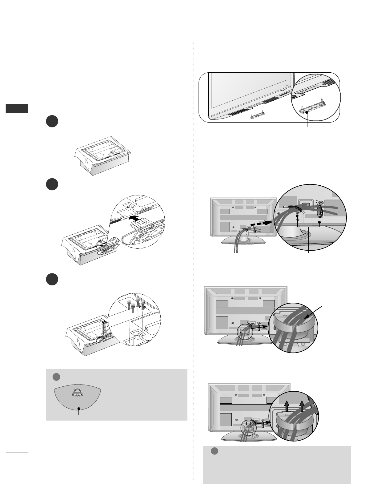
Stand Installation . . . . . . . . . . . . . . . . . . . . . . . . . 8
Not Using the desk-type stand . . . . . . . . . . . . . . .8
Back Cover for Wire Arrangement . . . . . . . . . . . . . 8
Careful installation advice . . . . . . . . . . . . . . . . . . . 9
Swivel Stand . . . . . . . . . . . . . . . . . . . . . . . . . . . . .10
Desktop Pedestal Installation . . . . . . . . . . . . . . . 10
Wall Mount: Horizontal Installation . . . . . . . . . . . 11
Antenna Connection . . . . . . . . . . . . . . . . . . . . . . 12
EXTERNAL EQUIPMENT SETUP
HD Receiver Setup . . . . . . . . . . . . . . . . . . . . . . . 13
D D Setup . . . . . . . . . . . . . . . . . . . . . . . . . . . . . 15
CR Setup . . . . . . . . . . . . . . . . . . . . . . . . . . . . . 18
A Output Setup . . . . . . . . . . . . . . . . . . . . . . . . 20
Digital Audio Out Setup . . . . . . . . . . . . . . . . . . 20
Other A/ Source Setup . . . . . . . . . . . . . . . . . . 21
Usb Setup . . . . . . . . . . . . . . . . . . . . . . . . . . . . . 22
PC Setup . . . . . . . . . . . . . . . . . . . . . . . . . . . . . . 23
- Screen Setup for PC Mode . . . . . . . . . . . . . 26
WATCHING TV / PROGRAMME CONTROL
Remote Control Key Functions . . . . . . . . . . . . . 30
Turning on the T . . . . . . . . . . . . . . . . . . . . . . . 34
Programme Selection . . . . . . . . . . . . . . . . . . . . 34
olume Adjustment . . . . . . . . . . . . . . . . . . . . . . 34
Quick Menu . . . . . . . . . . . . . . . . . . . . . . . . . . . . 35
On-Screen Menus Selection and Adjustment . . 36
Auto Programme Tuning . . . . . . . . . . . . . . . . . . . 37
Manual Programme Tuning (In Digital Mode) . . 38
Manual Programme Tuning (In Analogue Mode) . . 39
Programme Edit . . . . . . . . . . . . . . . . . . . . . . . . . 41
In DT /Radio Mode . . . . . . . . . . . . . . . . . . . . . . 42
In T Mode . . . . . . . . . . . . . . . . . . . . . . . . . . . . 43
Software Update . . . . . . . . . . . . . . . . . . . . . . . . 44
Diagnostics . . . . . . . . . . . . . . . . . . . . . . . . . . . . . 46
Selecting the Programme Table . . . . . . . . . . . . . 47
Input List . . . . . . . . . . . . . . . . . . . . . . . . . . . . . . 48
. . . . . . . . . . . . . . . . . . . . . . . . . . . . 49
Input Label . . . . . . . . . . . . . . . . . . . . . . . . . . . . . 52
A Mode . . . . . . . . . . . . . . . . . . . . . . . . . . . . . . 53
Initializing (Reset to original factory settings) . . .54
TO USE A USB DEVICE
When connecting a USB device . . . . . . . . . . . . . 55
Photo List . . . . . . . . . . . . . . . . . . . . . . . . . . . . . . 56
Music List . . . . . . . . . . . . . . . . . . . . . . . . . . . . . .60
Movie List . . . . . . . . . . . . . . . . . . . . . . . . . . . . . .63
DivX Registration Code . . . . . . . . . . . . . . . . . . . . . . . .67
Deactivation . . . . . . . . . . . . . . . . . . . . . . . . . . . . . . . . .68
EPG (ELECTRONIC PROGRAMME
GUIDE) (IN DIGITAL MODE)
- Switch on/off EPG . . . . . . . . . . . . . . . . . . . . 69
- Select Programme . . . . . . . . . . . . . . . . . . . . 69
- Button Function in NOW/NEXT Guide Mode . . 70
- Button Function in 7 Day Guide Mode . . . . 70
- Button Function in Date Change Mode . . . . 71
- Button Function in Extended Description Box . . 71
- Button Function in Remind Setting Mode . . . . . . . . 72
- Button Function in Schedule List Mode . . . . 72
PICTURE CONTROL
Picture Size (Aspect Ratio) Control . . . . . . . . . 73
ENERGY SA ING . . . . . . . . . . . . . . . . . . . . .75
Preset Picture Settings
- Picture Mode-Preset . . . . . . . . . . . . . . . . . . . 76
Manual Picture Adjustment
- Picture Mode-User option . . . . . . . . . . . . . . 77
Picture Improvement Technology . . . . . . . . . . . 78
Expert Picture Control . . . . . . . . . . . . . . . . . . . . 80

CONTENTS
3
Picture Reset . . . . . . . . . . . . . . . . . . . . . . . . . . . 83
Image Sticking Minimization (ISM) Method . . . 84
Demo Mode . . . . . . . . . . . . . . . . . . . . . . . . . . . .85
Mode Setting . . . . . . . . . . . . . . . . . . . . . . . . . . . .86
SOUND CONTROL
Auto olume Leveler . . . . . . . . . . . . . . . . . . . . . . 87
Preset Sound Settings - Sound Mode . . . . . . . . 88
Sound Setting Adjustment -User Mode . . . . . . 89
SRS TruSurround XT . . . . . . . . . . . . . . . . . . . . . 90
Clear oice II . . . . . . . . . . . . . . . . . . . . . . . . . . . 91
Balance . . . . . . . . . . . . . . . . . . . . . . . . . . . . . . . . 92
T Speakers On/ Off Setup . . . . . . . . . . . . . . . 93
Selecting Digital Audio Out . . . . . . . . . . . . . . . . 94
Audio Reset . . . . . . . . . . . . . . . . . . . . . . . . . . . . 95
Stereo Reception (In Analogue Mode Only) . . . . . . . . . . . . . 96
Speaker Sound Output Selection . . . . . . . . . . . 96
TIME SETTING
Clock Setup . . . . . . . . . . . . . . . . . . . . . . . . . . . . .97
Auto On/ Off Timer Setting . . . . . . . . . . . . . . . 98
Sleep Timer Setting . . . . . . . . . . . . . . . . . . . . . . 99
PARENTAL CONTROL / RATINGS
Set Password & Lock System . . . . . . . . . . . . . . 100
Block Programme . . . . . . . . . . . . . . . . . . . . . . . .101
Parental Control (In Digital Mode Only) . . . . . 102
Input Block . . . . . . . . . . . . . . . . . . . . . . . . . . . .103
Key Lock . . . . . . . . . . . . . . . . . . . . . . . . . . . . . . 104
TELETEXT (IN DIGITAL MODE ONLY)
Switch on/off . . . . . . . . . . . . . . . . . . . . . . . . . . 105
SIMPLE Text . . . . . . . . . . . . . . . . . . . . . . . . . . . 105
TOP Text . . . . . . . . . . . . . . . . . . . . . . . . . . . . . . 105
FASTEXT . . . . . . . . . . . . . . . . . . . . . . . . . . . . . . 106
Special Teletext Functions . . . . . . . . . . . . . . . . 106
APPENDIX
Troubleshooting . . . . . . . . . . . . . . . . . . . . . . . . 107
Maintenance . . . . . . . . . . . . . . . . . . . . . . . . . . 109
Product Specifications . . . . . . . . . . . . . . . . . . . 110
IR Codes . . . . . . . . . . . . . . . . . . . . . . . . . . . . . . 111
External Control Device Setup . . . . . . . . . . . . . 113

PREP R TION
4
PREP R TION
FRONT P NEL CONTROLS
■
Image shown may differ from your T .
CAUTION
GWhen the TV cannot be turned on with the remote control, press the main power button on the TV
(When the power is turned off with the main power button on the TV, it will not be turned on with the
remote control.)
Power/Standby Indicator
•
Illuminates red in standby mode.
•
The LED is off while the T remains on.
42/50PQ6***, 60PS6***
Remote Control
Sensor
Intelligent Sensor
Adjusts picture accord-
ing to the surrounding
conditions
MENU
INPUT
OK
P
P
PROGR MME
VOLUME
OK
MENU
INPUT
POWER
P
MENU
INPUT OK

5
PREP R TION
42/50PQ2***
OKMENUINPUT
P
MENU
INPUT OK
VOLUME POWER
P
MENUMENU
INPUTINPUT OKOK
P
MENU
INPUT OK
Power/Standby Indicator
•
Illuminates red in standby mode.
•
Illuminates blue when the T is
switched on.
Intelligent Sensor
Adjusts picture according
to the surrounding
conditions
P
MENU
INPUT OK
Remote Control
Sensor
PROGR MME
PROGR MMEVOLUMEMENU OKINPUT POWER
P
MENUMENU
INPUTINPUT OKOK
P
MENU
INPUT OK
P
MENU
INPUT OK
Intelligent Sensor
Adjusts picture according
to the surrounding
conditions.
Remote Control
Sensor
Power/Standby Indicator
• Illuminates red in standby mode.
•
Illuminates blue when the T is switched on.
P
MENU
INPUT OK
50PS3***

6
PREP R TION
PREP R TION
■
Image shown may differ from your T .
OK
MENU
INPUT P
PROGR MMEVOLUMEMENU OKINPUT
OKOK
MENUMENU
INPUTINPUT P
OK
MENU
INPUT P
Remote Control Sensor
POWER Button
Power/Standby Indicator
• illuminates red in standby mode.
• illuminates green when the T is
switched on.
60PS4***

7
PREP R TION
B CK P NEL INFORM TION
A
Image shown may differ from your T .
Power Cord Socket
This T operates on an AC power. The voltage is
indicated on the Specifications page. Never
attempt to operate the T on DC power.
OPTIC L DIGIT L UDIO OUT
Connect digital audio to various types of equipment.
Use to connect to a Digital Audio Component.
Use an Optical audio cable.
RGB/DVI udio Input
Connect the audio from a PC or DT .
HDMI Input
Connect a HDMI signal to HDMI IN or D I ( IDEO)
signal to HDMI/D I port with D I to HDMI cable.
RGB IN Input
Connect the output from a PC.
RS-232C IN (CONTROL & SERVICE) PORT
Connect to the RS-232C port on a PC.
This port is used for Service or Hotel mode.
udio/Video Input ( V IN1 / V IN2)
Connect audio/video output from an external
device to these jacks.
V Output
Connect second T or monitor to the A OUT
socket on the T .
Component Input
Connect a component video/audio device to
these jacks.
ntenna Input
Connect RF antenna to this jack.
USB Input
Connect USB storage device to this jack.
S-Video Input
Connect S- ideo out from an S- IDEO device.
1
2
3
4
5
8
9
10
11
R
VARIABLE AUDIO OUT
1
2
1
AV IN 2
L/MONO
R
AUDIO
VIDEO
S-VIDEO 3
AV
AUDIO IN
(RGB/DVI)
VIDED
R-AUDIO-L(MONO)
IN1 OUT
R - AUDIO - L VIDEO
COMPONENT IN
12
COMPONENT IN
AV IN 2
L/
L/
MONO
MONO
R
AUDIO
AUDIO
VIDEO
VIDEO
S-VIDEO
S-VIDEO
3
COMPONENT IN
COMPONENT IN
11
4
2
10456 9
7
6
3
12
12
7
78

8
PREP R TION
PREP R TION
ST ND INST LL TION
(Except for 60PS4***, 60PS6***)
1
2
3
Carefully place the T screen side down on a cushioned
surface to protect the screen from damage.
Assemble the T as shown.
Fix the 4 bolts securely using the holes in the
back of the T .
GGWhen assembling the stand,
make sure to distinguish and
assemble the front and rear
side of the stand correctly.
NOTE
!
FRONT
■
Image shown may differ from your T .
■
When assembling the desk type stand, check whether the
bolt is fully tightened. (If not tightened fully, the product
can tilt forward after the product installation.) If you
tighten the bolt with excessive force, the bolt can deviate
from abrasion of the tightening part of the bolt.
B CK COVER FOR WIRE
RR NGEMENT
■
Image shown may differ from your T .
After Connecting the cables as necessary, install
CABLE HOLDER as shown and bundle the cables.
CABLE HOLDER
■
Image shown may differ from your T .
When installing the wall-mounted unit, use the protection cover. Insert
the PPRROOTTEECCTTIIOONN CCOOEERRinto the T until clicking sound.
NOT USING THE DESK-TYPE ST ND
protection cover
Only 60PS4***, 60PS6***
Install the CCAABBLLEE MMAANNAAGGEEMMEENNTT CCLLIIPPas shown.
C BLE
M N GE-
MENT CLIP
Hold the CCAABBLLEE MMAANNAAGGEEMMEENNTT CCLLIIPPwith both
hands and pull it upward.
How to remove the ca le management clip
NOTE
!
GGDo not use the CABLE MANAGEMENT CLIP to
lift the T .
- If the T is dropped, you may be injured or the
T may be damaged.

9
PREP R TION
C REFUL INST LL TION DVICE
AYou should purchase necessary components to fix the T safety and secure to the wall from a hardware supplier.
APosition the TV close to the wall to avoid the possibility of it falling when pushed.
AThe instructions shown below are a safer way to set up the TV, by fixing it to the wall, avoiding the possibility
of it falling forwards if pulled. This will prevent the TV from falling forward and causing injury. This will also pre-
vent the TV from damage. Ensure that children do not climb or hang from the TV.
NOTE
!
G When moving the TV undo the cords first.
G Use a platform or cabinet strong and large enough to support the size and weight of the TV.
G To use the TV safely make sure that the height of the bracket on the wall and on the TV is the same.
3
1
2
Use the eye-bolts or T brackets/bolts to fix the product to the wall as shown in the picture.
(If your T has bolts in the eyebolts, loosen then bolts.)
* Insert the eye-bolts or T brackets/bolts and tighten them securely in the upper holes.
Secure the wall brackets with the bolts on the wall. Match the height of the bracket that is mounted on the
wall.
3Use a sturdy rope or wire to tie the product for alignment. It is safer to tie the rope so it becomes horizon-
tal between the wall and the product.
2
1
2
1

10
PREP R TION
PREP R TION
OK
MENU
INPUT P
DESKTOP PEDEST L INST LL TION
For adequate ventilation allow a clearance of 4” (10cm) all around the TV.
AThe TV can be installed in various ways such as on a wall, or on a desktop etc.
A The TV is designed to be mounted horizontally.
EARTHING
Ensure that you connect the earth wire to prevent possible
electric shock. If grounding methods are not possible, have
a qualified electrician install a separate circuit breaker.
Do not try to earth the T by connecting it to telephone
wires, lightening rods or gas pipes.
4 inches
4 inches
4 inches
SWIVEL ST ND
fter installing the TV, you can adjust the TV set manually to the left or right direction by 20 degrees to suit
your viewing position.
Power Supply
Circuit reaker
4 inches

11
PREP R TION
W LL MOUNT: HORIZONT L INST LL TION
AWe recommend the use of a LG Brand wall mounting bracket when mounting the TV to a wall.
AWe recommend that you purchase a wall mounting bracket which supports VES standard.
A LG recommends that wall mounting be performed by a qualified professional installer.
NOTE
!
G
Should Install wall mount on a solid wall perpendicular to the floor.
G
Should use a special wall mount, if you want to install it to ceiling or slanted wall.
G
The surface that wall mount is to be mounted on should be of sufficient strength to support the weight of TV set;
e.g. concrete, natural rock, brick and hollow block.
G
Installing screw type and length depends on the wall mount used. Further information, refer to the instructions
included with the mount.
G
LG is not liable for any accidents or damage to property or TV due to incorrect installation:
- Where a non-compliant VES wall mount is used.
- Incorrect fastening of screws to surface which may cause TV to fall and cause personal injury.
- Not following the recommended Installation method.
4 inches
4 inches
4 inches
4 inches
4 inches
AA
BB
Model ESA
(A *B) Standard
Screw Quantity
42PQ2***
50PQ2***
42PQ6***
50PQ6***
50PS3***
60PS4***
60PS6***
400* 400
400* 400
400* 400
400* 400
400* 400
600* 400
600* 400
M6
M6
M6
M6
M6
M8
M8
4
4
4
4
4
4
4

12
PREP R TION
PREP R TION
AV IN 2
L/MONO
R
AUDIO
VIDEO
S-VIDEO 3
COMPONENT IN
COMPONENT IN
AV IN 2
L/MONO
R
AUDIO
VIDEO
S-VIDEO 3
COMPONENT IN
COMPONENT IN
NTENN CONNECTION
AV IN 3
L/ MONO
R
AUDIO
VIDEO
S-VIDEO HDMI IN 3
■For optimum picture quality, adjust antenna direction.
■An antenna cable and converter are not supplied.
■To prevent damage do not connect to the mains outlet until all connections are made between the devices.
Multi-family Dwellings/Apartments
(Connect to wall antenna socket)
Single-family Dwellings /Houses
(Connect to wall jack for outdoor antenna)
Outdoor
ntenna
(VHF, UHF)
Wall
ntenna
Socket
RF Coaxial Wire (75 ohm)
Antenna
UHF
Signal
Amplifier
VHF
■In poor signal areas, to achieve better picture quality it may be necessary to install a signal amplifier to the
antenna as shown above.
■If signal needs to be split for two T s, use an antenna signal splitter for connection.

13
EXTERN L EQUIPMENT SETUP
HD RECEIVER SETUP
■To avoid damaging any equipment, never plug in any power cords until you have finished connecting all equipment.
■This section on EXTERN L EQUIPMENT SETUP mainly uses diagrams for the 42/50PQ6*** models.
■
Image shown may differ from your T .
Connecting with a component ca les
AV IN 1 AV OUT
L/MONO
R
AUDIO
VIDEO
L
R
AUDIO
VIDEO
COMPONENT IN
COMPONENT IN
12
1
2
Signal
480i/576i
480p/576p
720p/1080i
108 0 p
Component
O
O
O
O
(50Hz/60Hz only)
HDMI
X
O
O
O
(24Hz/30Hz/50Hz/60Hz)
■This T can receive Digital RF/Cable signals without an external digital set-top box. However, if you do receive
Digital signals from a digital set-top box or other digital external device, refer to the diagram as shown below.
Connect the video outputs (Y, PB, PR)of the digital set
top box to the CCOOMMPPOONNEENNTT IINN IIDDEEOOjacks on the
T .
Connect the audio output of the digital set-top box to
the CCOOMMPPOONNEENNTT IINN AAUUDDIIOOjacks on the T .
Turn on the digital set-top box.
(Refer to the owner’s manual for the digital set-top box.)
Select CCoommppoonneenntt 11input source using the IINNPPUUTT
button on the remote control.
If connected to CCOOMMPPOONNEENNTT IINN 22input, select
CCoommppoonneenntt 22 input source.
2
3
4
1

14
EXTERN L EQUIPMENT SETUP
Connecting a set-top ox with an HDMI ca le
2
1
AV IN 1 AV OUT
L/MONO
R
AUDIO
VIDEO
L
R
AUDIO
VIDEO
COMPONENT IN
COMPONENT IN
1
Connecting with an HDMI to DVI ca le
AV IN 1 AV OUT
L/MONO
R
AUDIO
VIDEO
L
R
AUDIO
VIDEO
AV
AUDIO IN
(RGB/DVI)
VIDEO
R-AUDIO-L(MONO)
IN1 OUT
R - AUDIO - L VIDEO
COMPONENT IN
1
2
1
COMPONENT IN
12
Connect the digital set-top box to HHDDMMII//DDII IINN 11,
HHDDMMII IINN 22 or HHDDMMII IINN 33jack on the T .
Turn on the digital set-top box.
(Refer to the owner’s manual for the digital set-top box.)
Select HHDDMMII11, HHDDMMII22or HHDDMMII33 input source using
the IINNPPUUTTbutton on the remote control.
2
3
1
Connect the digital set-top box to HHDDMMII//DDII IINN 11
jack on the T .
Connect the audio output of the digital set-top box to
the AAUUDDIIOO IINN ((RRGGBB//DDII)) jack on the T .
Turn on the digital set-top box. (Refer to the owner’s
manual for the digital set-top box.)
Select HHDDMMII11input source using the IINNPPUUTTbutton
on the remote control.
2
3
4
1
NOTE
!
G
Check your HDMI cable is over version 1.3.
I
f the HDMI cables don’t support HDMI version 1.3, it can
cause flickers or no screen display. In this case use the latest
cables that supprot HDMI version 1.3.

15
EXTERN L EQUIPMENT SETUP
DVD SETUP
Connecting with a component ca les
AV IN 1 AV OUT
L/MONO
R
AUDIO
VIDEO
L
R
AUDIO
VIDEO
COMPONENT IN
COMPONENT IN
12
Component Input ports
To achieve better picture quality, connect a DVD player to the component input ports as shown below.
Component ports on the T
YPBPR
ideo output ports
on D D player
Y
Y
Y
Y
PB
B-Y
C
P
PR
R-Y
Cr
Pr
1
2
Connect the video outputs (Y, PB, PR)of the D D to the
CCOOMMPPOONNEENNTT IINN IIDDEEOOjacks on the T .
Connect the audio outputs of the D D to the
CCOOMMPPOONNEENNTT IINN AAUUDDIIOOjacks on the T .
Turn on the D D player, insert a D D.
Select CCoommppoonneenntt 11input source using the IINNPPUUTT
button on the remote control.
If connected to CCOOMMPPOONNEENNTT IINN 22input, select
CCoommppoonneenntt 22 input source.
Refer to the D D player's manual for operating
instructions.
2
3
4
5
1

16
EXTERN L EQUIPMENT SETUP
Connecting with a S-Video ca le
L R
S-VIDEOVIDEO
OUTPUT
SWITCH
ANT IN
ANT OUT
2
HDMI IN 3
Connect the S- IDEO output of the D D to the SS--
IIDDEEOOinput on the T .
Connect the audio outputs of the D D to the AAUUDDIIOO
input jacks on the T .
Turn on the D D player, insert a D D.
Select AA22input source using the IINNPPUUTTbutton on
the remote control.
Refer to the D D player's manual for operating
instructions.
2
3
4
5
1
12

17
EXTERN L EQUIPMENT SETUP
2
1
2
Connecting the HDMI ca le
Connect the HDMI output of the D D to the
HHDDMMII//DDII IINN 11,HHDDMMII IINN 22,orHHDDMMII IINN 33 jack on
the T .
Select HHDDMMII11, HHDDMMII22or HHDDMMII33 input source using
the IINNPPUUTTbutton on the remote control.
Refer to the D D player's manual for operating
instructions.
2
3
1
1
GGThe T can receive video and audio signals simultaneously
when using a HDMI cable.
GGIf the D D does not support Auto HDMI, you must set the
output resolution appropriately.
GGCheck that your HDMI cable is version 1.3 or higher.
If the HDMI cables don’t support HDMI version 1.3, flicker-
ing or no screen display can result. Please use the latest
cables that support at least HDMI version 1.3.
NOTE
!

18
EXTERN L EQUIPMENT SETUP
VCR SETUP
■To avoid picture noise (interference), allow adequate distance between the VCR and TV.
AV IN 1 AV OUT
L/MONO
R
AUDIO
VIDEO
L
R
AUDIO
VIDEO
OUTPUT
SWITCH
ANT IN
R
S-VIDEO VIDEO
ANT OUT L
2
2
RAUDIO L(MON
IN1 OUT
R - AUDIO - L
COMPONENT IN
12
Wall Jack
Antenna
1
2
Connecting with a RF Ca le
Connect the AANNTT OOUUTTsocket of the CR to the AANNTTEENNNNAA IINNsocket on the T .
Connect the antenna cable to the AANNTT IINNsocket of the CR.
Press the PPLLAAYYbutton on the CR and match the appropriate channel between the T and CR for
viewing.
2
3
1
This manual suits for next models
6
Table of contents
Other LG Plasma TV manuals

LG
LG 60PB6500 User manual

LG
LG DU-42PY10X User manual

LG
LG 42PT200 User manual

LG
LG 42PC1RR Series User manual

LG
LG 50PN4500-UA User manual

LG
LG 50PG20-UA User manual

LG
LG 42PX5D - 42 Plasma Integrated HDTV User manual

LG
LG 50PC1D Series User manual

LG
LG 50PJ340 Installation guide

LG
LG 50PS60 Series User manual