LG 42PX4DV User manual

PLASMA TV
SERVICE MANUAL
CAUTION
BEFORE SERVICING THE CHASSIS,
READ THE SAFETY PRECAUTIONS IN THIS MANUAL.
CHASSIS : DF-057A
MODEL : 42PX4DV
42PX4DV-AA
website:http://biz.LGservice.com
e-mail:http://www.LGEservice.com/techsup.html

- 2 -
CONTENTS
SAFETY PRECAUTIONS ....................................................................................3
DESCRIPTION OF CONTROLS..........................................................................4
SPECIFICATIONS................................................................................................8
ADJUSTMENT INSTRUCTIONS .......................................................................10
TROUBLE SHOOTING GUIDE..........................................................................13
BLOCK DIAGRAM.............................................................................................21
EXPLODED VIEW..............................................................................................22
EXPLODED VIEW PARTS LIST ........................................................................23
REPLACEMENT PARTS LIST...........................................................................24
SCHEMATIC DIAGRAM.........................................................................................
PRINTED CIRCUIT BOARD ..................................................................................

- 3 -
SAFETY PRECAUTIONS
Many electrical and mechanical parts in this chassis have special safety-related characteristics. These parts are identified by in
the Schematic Diagram and Replacement Parts List.
It is essential that these special safety parts should be replaced with the same components as recommended in this manual to
prevent X-RADIATION, Shock, Fire, or other Hazards.
Do not modify the original design without permission of manufacturer.
General Guidance
An isolation Transformer should always be used during
the servicing of a receiver whose chassis is not isolated from
the AC power line. Use a transformer of adequate power rating
as this protects the technician from accidents resulting in
personal injury from electrical shocks.
It will also protect the receiver and it's components from being
damaged by accidental shorts of the circuitry that may be
inadvertently introduced during the service operation.
If any fuse (or Fusible Resistor) in this monitor is blown, replace
it with the specified.
When replacing a high wattage resistor (Oxide Metal Film
Resistor, over 1W), keep the resistor 10mm away from PCB.
Keep wires away from high voltage or high temperature parts.
Due to high vacuum and large surface area of picture tube,
extreme care should be used in handling the Picture Tube.
Do not lift the Picture tube by it's Neck.
Leakage Current Cold Check(Antenna Cold Check)
With the instrument AC plug removed from AC source,
connect an electrical jumper across the two AC plug prongs.
Place the AC switch in the on position, connect one lead of
ohm-meter to the AC plug prongs tied together and touch other
ohm-meter lead in turn to each exposed metallic parts such as
antenna terminals, phone jacks, etc.
If the exposed metallic part has a return path to the chassis, the
measured resistance should be between 1MΩ and 5.2MΩ.
When the exposed metal has no return path to the chassis the
reading must be infinite.
An other abnormality exists that must be corrected before the
receiver is returned to the customer.
Leakage Current Hot Check (See below Figure)
Plug the AC cord directly into the AC outlet.
Do not use a line Isolation Transformer during this check.
Connect 1.5K/10watt resistor in parallel with a 0.15uF capacitor
between a known good earth ground (Water Pipe, Conduit, etc.)
and the exposed metallic parts.
Measure the AC voltage across the resistor using AC
voltmeter with 1000 ohms/volt or more sensitivity.
Reverse plug the AC cord into the AC outlet and repeat AC
voltage measurements for each exposed metallic part. Any
voltage measured must not exceed 0.75 volt RMS which is
corresponds to 0.5mA.
In case any measurement is out of the limits specified, there is
possibility of shock hazard and the set must be checked and
repaired before it is returned to the customer.
Leakage Current Hot Check circuit
1.5 Kohm/10W
To Instrument's
exposed
METALLIC PARTS
Good Earth Ground
such as WATER PIPE,
CONDUIT etc.
AC Volt-meter
IMPORTANT SAFETY NOTICE
0.15uF

D/A TV INPUT
TV
DVD
VCR
SLEEP
GUIDE
INFO
MENU
TEXT
MUTE
LIST
SIZE UPDATE INDEX
STILL
TIME REVEAL MIX
I/II
PIP PR- PIP PR+ SWAP
PIP PSM SSM
PIP INPUT
Q.VIEW
FAV
OK
VOL PR
EXIT
POWER
ARC
?
INPUT
Selects the
Digital, Analogue, Video 1, Video
2, Component 1, Component 2, RGB-PC,
RGB-DTV or HDMI/DVI
modes.
switches the set on from standby.
VCR/DVD BUTTONS
Controls a LG video cassette recorder.
controls a LG DVD player.
POWER
switches the set on from standby or off to
standby.
ARC
Changes the picture format.
SSM
To select the sound appropriate to your
viewing programme.
EXIT
Clears all on-screen displays and returns to
TV viewing from any menu.
TEXT
These buttons are used for teletext.
For further details, see the ‘Teletext’ section.
COLOURED BUTTONS : These buttons are
used for teletext (only TELETEXT models) or
programme edit.
FAV
selects a favourite programme.
I/II
selects the sound output or the audio mode.
Q.VIEW
Returns to the previously viewed programme.
VOL +/- (Volume Up/Down)
Increases/decreases sound level.
PR +/- (Programme Up/Down)
Selects a programme.
SLEEP
Sets the sleep timer.
D/A TV
selects analogue or digital mode.
MODE
Selects another device.
GUIDE
shows a programme schedule.
(In Digital mode only)
MENU
Displays on screen menus one by one.
Exits the current menu.
Memorizes menu changes.
INFO
displays information on top of the screen
whilst watching the TV.
(In Digital mode only)
MUTE
Switches the sound on or off.
NUMBER buttons
LIST
Displays the programme table.
PSM
Adjusts the factory preset picture according
to the room.
PIP
Switches the sub picture on or off.
Selects PIP or DW modes.
PIP PR + /-
Selects a programme for the sub picture.
SWAP
Alternates between main and sub picture.
PIP INPUT
Selects the input mode for the sub picture.
OK
accepts your selection or displays the
current mode.
D/ E or F/ G
Adjusts menu settings.
Selects menu item.
- 4 -
DESCRIPTION OF CONTROLS

- 5 -
PR
VOL
MENUTV/AV OK
21 3 4 5 6
7
8
1. Power Button
2. Remote Control Sensor
3. TV/AV Button
Selects the Digital, Analogue, Video 1, Video 2, Component
1, Component 2, RGB-PC, RGB-DTV or HDMI/DVI modes.
Switches the set on from standby.
4. MENU
Displays on screen menus one by one.
Exits the current menu.
Memorizes menu changes.
5. OK
Accepts your selection or displays the current mode.
6. DD/ EE(Programme Up/Down)
Selects a programme or a menu item.
Switches the set on from standby.
FF/ GG(Volume Up/Down)
Adjusts the volume.
Adjusts menu settings.
7. Power Standby Indicator
Illuminates red in standby mode, Illuminates green when
the set is turned on
8 . Intelligent Eye
Adjusts picture according to the surrounding conditions.
< Front Panel Controls >

- 6 -
1. UPGRADE PORT
This port is used to upgrade the software version and debug
without changing the hardware.
Be careful not to use this port. Just contact your dealer or ser-
vice centre.
2. CONTROL LOCK / REMOTE CONTROL
3. DVI INPUT/COMPONENT 1 INPUT/OUTPUT (DIGITAL
AUDIO (OPTICAL))
Connect digital audio from various types of equipment.
Note: In standby mode, these ports will not work.
4. HDMI/DVI INPUT / AUDIO INPUT / RGB INPUT (PC/DTV)
Connect the monitor output socket of the PERSONAL COM-
PUTER to this socket.
Note: If you want to use RGB/DVI audio, we strongly recom-
mend that you use the cable that has a core, or the EMI Filter
core along with separate cable.
5. COMPONENT INPUT
Connect DVD video outputs to Y, PB, PRof COMPONENT
INPUT and audio outputs to Audio sockets of AUDIO INPUT.
6. AUDIO/VIDEO IN SOCKETS (A/V INPUT1)
Connect the audio/video out sockets of external equipment to
these sockets.
S-VIDEO/AUDIO IN SOCKETS
Connect the S-VIDEO out socket of the VCR to the S-VIDEO
socket.
Connect the audio out sockets of the VCR to the audio sock-
ets as in A/V INPUT1.
AUDIO/VIDEO OUT SOCKETS (MONITOR OUTPUT)
7. ANTENNA INPUT
8. POWER CORD SOCKET
This Monitor operates on AC power. The voltage is indicated
on the Specifications page. Never attempt to operate the
Monitor on DC power.
9. AUDIO/VIDEO IN SOCKETS (A/V INPUT2)
S-VIDEO/AUDIO IN SOCKETS
VIDEO
S-VIDEO
AUDIO
R
L/MONO
A/V INPUT2A/V INPUT2
AC INPUT
1
9
2 3 4 5 6 7 8
<Back Panel>

- 7 -
AS mark
LG TV
Owner’s Manual
1.5V
1.5V
Alkaline batteries Power Cord
D/ATV INPUT
TV
DVD
VCR
SLEEP
GUIDE
INFO
MENU
TEXT
MUTE
LIST
SIZE UPDATE INDEX
STILL
TIME REVEAL MIX
I/II
PIPPR- PIPPR+ SWAP
PIP PSM SSM
PIPINPUT
Q.VIEW
FAV
OK
VOL PR
EXIT
POWER
ARC
?
Remote Control handset
-Optional extras can be changed or modified for quality improvement. Without any notification new optional extras can be
added.
- Contract your dealer for buying these items.
Optional Extras
Accessories
Tilt wall mounting bracket Video cables Audio cables
Ceiling mounting bracket
40
42
50
42
40
-Secure the set assembly by fixing it to a wall by using the Eye Bolts/Wall brackets.
Fixing the set assembly to the wall to protect the set tumbling
•If the set is mounted on a desk top, insert the 2 Eye-Bolts and tighten them
securely in the upper holes as shown.
Install the wall brackets on the wall with 2 bolts*, (not supplied with the product),
as shown.
Match the height of the Eye-Bolts and the wall brackets.
Check to be sure the Eye-Bolts and the brackets are tightened securely.
• Secure the set assembly to the wall with strong strings or wound wire cables,
(not supplied with the product), as shown.
2-Wall brackets
2-Eye Bolts

SPECIFICATIONS
NOTE : Specifications and others are subject to change without notice for improvement
.
- 8 -
VApplication Range
This spec is applied to the 42”/50”/60”PDP TV used DF-057A Chassis.
V Specification
Each part is tested as below without special appointment.
1) Temperature : 25±5°C (77±9°F), CST : 40±5
2) Relative Humidity: 65±10%
3) Power Voltage: Standard Input voltage (100-240V~, 50/60Hz)
* Standard Voltage of each product is marked by models.
4) Specification and performance of each parts are followed each drawing and specification by part number in accordance with BOM.
5)
The receiver must be operated for about 20 minutes prior to the adjustment
.
VTest Method
1) Performance : LGE TV test method followed.
2) Demanded other specification
Safety: CE, IEC specification
EMC : CE, IEC
VGeneral Specification
1. SET(42PX4DV-AA)
Remark
Safety : IEC60065, EN60065
EMC : CISPR 13 Class B
Model Name
42PX4DV
Market
Australia
Broadcasting system
Available Channel
Tuner IF
Input Voltage
PDP Module
Aspect ratio
Operating Temperature
Operating Humidity
Storage Temperature
Storage Humidity
1
2
3
4
5
6
7
8
9
10
No Item Specification Remark
Min Typ Max Unit
PAL-B/G, DTV : DVB-T
VHF : 00~12
UHF : 28~69
CATV : 02~44
DTV : 06~12, 27~69
PAL : 38.90 MHz
DVB-T : 36.167 MHz
240V~, 50Hz
PDP42V7xxxx,
RGB Closed Type, Film Filter
16:9(wide)
040 deg
85 %
-20 60 deg
85 %
Maker : Sanken

2. PDP Module(PDP42V7xxxx)(film Filter)
- 9 -
Display area
Outline dimension
Number of Pixels
Cell Pitch
Color arrngement
Weight(net)
weight(gross)
Operating Temperature
Environment Humidity
Pressure
Storage Temperature
Environment Humidity
Pressure
Image stick Start time
minimization Low Brightness
mode Arrival Time
1
2
3
4
5
6
7
8
9
10
No Item Specification Remark
Min Typ Max Unit
920.1(H) * 518.4(V) ± 0.54.8 mm
1005(H) * 597(V) * 61.2(D) ± 1 mm
852(H) *480(V)
320(H) * 1080(V)
U
m
RGB closed type
14.3 14.8 15.3 Kg
106.0 111.0 116.0 Kg
0 ~ 40 deg
20 ~ 80 %
800 ~ 1100 hPa
-20 ~ 60 deg
10 ~ 90 %
700 ~ 1100 hPa
4.5 5 5.5 min
14 15 16 min
Maker : Sanken

- 10 -
1. Application Object
These instructions are applied to all of the PDP TV, DF-057A.
2. Notes
(1) Because this is not a hot chassis, it is not necessary to use
an isolation transformer. However, the use of isolation
transformer will help protect test equipment.
(2) Adjustments must be done in the correct order.
(3) The adjustments must be performed in the circumstance of
25±5°C of temperature and 65±10% of relative humidity if
there is no specific designation.
(4) The input voltage of the receiver be must kept 220V, 60Hz
when adjusting.
(5) The receiver must be operational for about 15 minutes
prior to the adjustments.
OAfter receiving 100% white pattern, the receiver must be
operate prior to adjustment.(Or white condition in HEAT-
RUN mode)
OEnter into HEAT-RUN MODE
- Press the POWER ON KEY on R/C for adjustment.
OSD display and screen display 100% full WHITE
PATTERN.
[Set is activated HEAT-RUN without signal generator in
this mode.
If you turn on a still screen more than 20 minutes (Especially
Digital pattern, Cross Hatch Pattern), an afterimage may occur
in the black level part of the screen.
3. EPLD Download
(1) Test Equipment: PC, Jig for download
(2) Connect the power of VSC B/D.
(3) Execute download program of PC.
(4) After executing the hot key on the Programmer, click
Program icon
(5) End after confirming.
4. POWER PCB Assy Voltage
Adjustment (Va, Vs Voltage Adjustment)
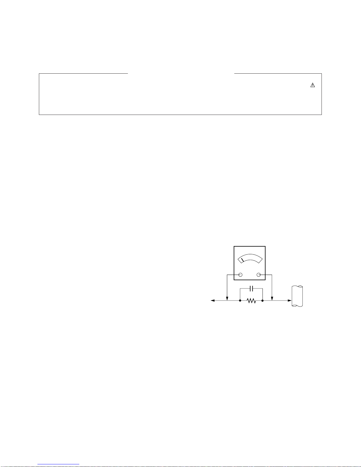
4-1. Test Equipment : D.M.M 1EA
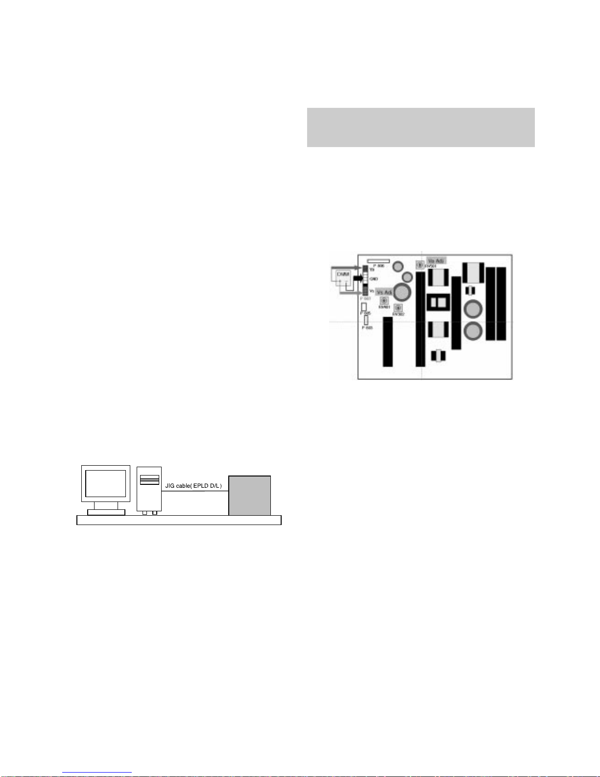
4-2. Adjustment Method (3501V00220A)
(1) Connection Diagram for Measuring : fig. 4-1
(2) Va Adjustment
1) After receiving 100% Full White Pattern by Video/RGB
or selecting White Mode of Heat-Run Mode, Execute
HEAT RUN over 10 minutes.
2) Connect + terminal of D.M.M to Va pin of P807, and
connect - terminal to GND pin of P807.
3) After turning RV501, voltage of D.M.M adjustment as
same as Va voltage which on label of panel right/top.
(Deviation; ±0.5V)
(3) Vs Adjustment
1) Connect + terminal of D.M.M to Vs pin of P807, connect
– terminal to GND pin of P807.
2) After turning RV401, voltage of D.M.M adjustment as
same as Va voltage which on label of panel right/top.
(Deviation; ±0.5V)
4-3. Adjustment Method (3501V00221A)
(1) Connection Diagram for Measuring : fig. 4-2
(2) Va Adjustment
1) After receiving 100% Full White Pattern by Video/RGB
or selecting White Mode of Heat-Run Mode, Execute
HEAT RUN over 10 minutes.
2) Connect + terminal of D.M.M to Va pin of P805 and
connect – terminal to GND pin of P805.
3) After turning RV601, adjust voltage of D.M.M as same
as Va voltage which on label of panel right/top.
(Deviation; ±0.5V)
ADJUSTMENT INSTRUCTIONS
PC VSC
B/D
<Fig 1> Connection Diagram of EPLD Download
Each PCB Assy must be checked by Check JIG Set before
assembly. (Especially, be careful Power PCB Assy which can
cause Damage to the PDP Module.)
<Fig. 4-1> Connection diagram of power adjustment for measuring

- 11 -
(3) Vs Adjustment
1) Connect + terminal of D.M.M to Vs pin of P805 and
connect – terminal to GND pin of P805.
2) After turning RV401, adjust voltage of D.M.M as same as
Va voltage which on label of panel right/top. (Deviation;
±0.5V)
5. EDID(The Extended Display Idetification Data)
/ DDC(Display Data Channel) Download
This is the function that enables “Plug and Play".
5-1. Required Test Equipment
1) PC, Jig for adjusting DDC (PC serial to D-sub.
Connection equipment)
2) DVI to HDMI Connector
5-2. Composition of Device
5-3. EDID DATA
- Download only EDID for HDMI.
6. AD9883A-Set Adjustment
6-1. Synopsis
AD9883A-Set adjustment to set the black level and the Gain
of optimum with an automatic movement from the analog =>
digital converter.
6-2. Test Equipment
Service R/C, MSPG925 Series Pattern Generator
(720P 60Hz 100% Color Bar Pattern output will be possible
and the output level will accurately have to be revised with
0.7±0.1Vp-p)
6-3. Adjustment
(1) Input the color Bar Pattern of the 720P 60Hz Mode what is
supportable to Component or RGB INPUT and the select
the Input Mode as Component2.
(2) After receiving signal for at least 1 second, press the ADJ
Key on the Service R/C to enter the ‘Ez - Adjust’ and then
select the ‘1. AD9883A-Set’.
Pressing the Vol + Key to adjust with automatic movement.
(3) If Component adjustment is completed normality,
'Component Adjustment OK' is displayed and if RGB
adjustment is completed normality, 'RGB Adjustment OK' is
displayed. If the adjustment has errors, 'AD9883A-Failed!
Try Again' is displayed.
(4) Readjust after confirming the case Pattern or adjustment
condition where the adjustment errors.
(5) After adjustment is complete, exit the adjustment mode by
pressing the ADJ KEY.
7. Adjustment of White Balance
7-1. Required Equipment
(1) Color analyzer (CA-100 or similar product)
(2) Automatic adjustor (with automatic adjustment hour
necessity and the RS-232C communication being possible)
(3) AV Pattern Generator
Va ADJ
RV601
P806
P805
P807
Va
GND
NC
VS
DMM
+ - P804
P801 P802
Vs ADJ
V401
P803
<Fig. 4-2> Connection diagram of power adjustment for measuring
PDP
SET
00 |
10 |
20 |
30 |
40 |
50 |
60 |
70 |
80 |
90 |
A0 |
B0 |
C0 |
D0 |
E0 |
F0 |
00
00
23
0F
01
13
3E
47
00
02
83
16
72
00
8C
00
21
01
FF
0E
4B
01
00
08
20
00
03
01
20
1C
BC
0A
18
00
02
FF
01
52
01
4C
00
54
00
1A
00
58
16
52
D0
01
00
03
FF
03
EF
01
6C
00
56
00
72
00
2C
20
D0
90
1D
1E
04
FF
80
CE
01
42
00
0A
00
23
65
25
10
1E
20
00
00
05
FF
6E
00
01
00
00
20
00
09
03
00
2C
20
40
72
00
06
FF
3E
31
C3
00
00
20
00
07
0C
C4
25
B8
31
51
00
07
00
78
CA
1E
18
00
20
00
02
00
8E
80
28
20
D0
00
08
1E
0A
01
00
00
00
20
00
47
10
21
C4
55
0C
1E
00
09
6D
31
01
20
00
00
20
00
81
00
00
8E
40
40
20
00
0A
01
30
01
41
00
00
20
00
03
01
00
21
C4
55
6E
00
0B
01
A5
01
00
FD
00
20
00
05
1D
9E
00
8E
00
28
00
0C
01
58
01
20
00
00
00
00
14
80
01
00
21
C4
55
00
0D
01
3B
01
30
37
FC
00
00
13
18
1D
9E
00
8E
00
00
0E
01
B8
01
10
4E
00
00
01
12
71
80
01
00
21
C4
00
0F
01
26
01
60
1E
4C
01
57
04
1C
D0
1D
1E
00
8E
50
<Fig. 6> Adjustment Pattern : 720P 60Hz Color Bar Pattern

- 12 -
7-2. Connection Diagram of Equipment
for Measuring (Automatic Adjustment)
[[. RS-232C Command (Automatic Adjustment)
7-3. Adjustment of White Balance(manual)
O
Operate the Zero-calibration of the CA-100, then attach
sensor to PDP module surface when you adjust.
O
Manual adjustment is also possible by the following sequence.
(1) Enter ‘3.White-Pattern’ by pressing ADJ KEY on the
Service Remote Control.
(2) Select "Test Pattern White" using Vol +/- Key and Execute
HEAT RUN at least 15 minutes.
(3) Receive the HDMI/DVI 720p 60Hz, Full size, 216 Gray
window pattern signal from AV Pattern Generator.
Input mode : HDMI/DVI
(4) Select the condition of screen Adjustment as ‘Dynamic’.
(5) After attaching sensor to center of screen, select ‘2. White-
Balance’ in ‘Ez - Adjust’ by pressing the ADJ KEY on the
Service R/C. Then enter adjustment mode by pressing the
Right KEY (
G
) .
(6) Adjust the High Light using R Gain/B Gain.
(7) Adjust using Volume +/- KEY.(R Gain: 128)
R Offset : 64/ G Offset : 56/ B Offset: 64(fixing)
X; 0.290±0.003
Y; 0.290±0.003
Color temperature: 9,000°K±500°K
(8) After adjustment is complete, move to Ez - Adjust screen
by pressing the ENTER(A) KEY. Then exit the adjustment
mode by press ADJ KEY.
216 FULL WHITE
HDMI signal input
PDP MONITOR
COLOR
ANALYZER
TYPE; CA-100
MSPG-925 Series
R Gain
G Gain
B Gain
R Cut
G Cut
B Cut
00
00
00
00
00
00
ff
ff
ff
7f
7f
7f
ja 00 XX
jb 00 XX
jc 00 XX
lj 00 XX
lk 00 XX
ll 00 XX
80(Fix.)
80
80
40(Fix.)
38(Fix)
40(Fix)
RS-232C Command
[CMD ID DATA] MIN CENTER
(DEFAULT) MAX
<Fig. 7> Connection Diagram of Automatic Adjustment

- 13 -
1. Sanken Power Board Structure
1 2 3
T221: Vs Trans
T271: Va Trans
T121: St-by Trans
T201: Low Voltage Trans
TOUBLE SHOOTING

2. No Power
(1) Symptom
¯It is not discharged minutely from the module.
¯Light does not come in into the front LED.
(2) Check following
- 14 -
Is plug in the power cord? Plug in the power cord.
Yes
No
Is the Line Filter and Power
Board Cable connected? Connect the Cable.
Yes
No
Is the Fuse(F101)
on Power Board normal? Replace the Fuse.
Yes
No
Yes
Is the Power Board and
VSC Board Cable connected? Connect the Cable.
Yes
No
Is the Power cables of the VSC
Board Cable connected? Replace the cables.
No
After the cable connect is
removed to Power Board(except
the CN101 connection cable), the
AC voltage marking is authorized
on manual. When ST-BY 5V is not
operated, replace Power Board

- 15 -
3. Protect Mode
(1) Symptom
¯After once shining, it does not discharged minutely
from the module
¯The Rely falls(The sound is audible “click”)
¯It is converted with the color where the front LED
is red from green.
(2) Check following
Is the Power Board
normal? Replace Power
Board.
Is output the normality Low/High
voltage except Stand-by 5V?
Yes
No No
Is normal the each
connector? Replace the
connector.
Replace
Y-Board.
After connecting well each connector,
the normality it operates?
Yes
No No
Is the Ctrl Board
normal? Replace
X-Board.
Is the output voltage normal after
remove P1, 2, 4, 9, 10 connector of
Ctrl-B/D?
Yes
No Yes
Is the Y- Board
normal?
Is the output voltage
normal after remove
P5, P6 connector of
Y-B/D?
Is the Fuse(FS2) on Y-B/D normal?
(In case of open is replace)
Yes
No Yes Yes
Replace
Z-Board.
Is the Z- Board
normal?
Is the output voltage
normal after remove
P1 connector of
Z-B/D?
Is the Fuse(FS1, FS2) on Z-B/D
normal? (In case of open is replace)
Yes
No Yes
Is the X- Board
normal?
Is the output voltage normal after
remove P1, 2, 3, 4, 5 connector of
X-B/D?
After remove P1, P2, P3 output voltage
normality: Replace Right X-B/D
After remove P4, P5 output voltage
normality: Replace Left X-B/D
Yes
No Yes
Is the VSC Board
normal? Is the output voltage normal after
remove P1001, P1100?
After crisis COF of each board, check the normality operates.
If in case normality operates, correspondence COF Fail is
replace the module.
After remove P1001, 1100 normal
operation: Replace VSC Board
Yes
No
Is the COF of X, Y, Z
normal?
No
Yes
Yes

- 16 -
4. No Raster
(1) Symptom
¯It does not discharged from the module.
¯It maintains the condition where the front LED is green.
(2) Check following
Is the Power Board
normal? Replace Power
Board.
Is output the normality Low/High
voltage except Stand-by 5V?
Yes
No No
Is the each connector
normal? Replace the
connector.
Replace
Y-Board.
After connecting well each connector,
the normality it operates?
Yes
No No
Is the
Ctrl Board normal? Replace
X-Board.
Is the output voltage after remove
P1, 2, 4, 9, 10 connectorof Ctrl-B/D
normal?
Yes
No Yes
Is the
Y- Board normal?
Is the output voltage
normal after remove
P5, P6 connector of
Y-B/D?
Is the Fuse(FS2) on Y-B/D normal?
(In case of open is replace)
Yes
No Yes Yes
Replace
Z-Board.
Is the
Z- Board normal?
Is the output voltage
normal after remove
P1 connector of
Z-B/D?
Is the Fuse(FS1, FS2) on Z-B/D
normal? (In case of open is replace)
Yes
No Yes
Is the
X- Board normal?
Is the output voltage after remove
P1, 2, 3, 4, 5 connector ofX-B/D
normal?
After remove P1, P2, P3 output voltage
normality: Replace Right X-B/D
After remove P4, P5 output voltage
normality: Replace Left X-B/D
Yes
No Yes
Is the
VSC Board normal? Is the output voltage normal after
remove P1001, P1100?
After crisis COF of each board, check the normality operates.
If in case normality operates, correspondence COF Fail is
replace the module.
After remove P1001, P1100 normal
operation: Replace VSC Board
Yes
No
Is the COF of X, Y, Z
normal?
No
Yes
Yes

- 17 -
5. In the case of occur strange screen into specific mode
5-1. In case of does’t display the OSD
(1) Symptom
¯LED is green
¯The minute discharge continuously becomes
accomplished from module
(2) Check following
Is the LVDS cable
normal?
Is the VSC Digital
Board normal?
Is the LVDS cable
connected correctly?
Connect the cable correctly.
Yes
No
No
Yes
Does the Thine IC
(IC1401)operates ?
Replace Thine
IC(IC1401).
No
Is the Ctrl Board of
Module normal? Replace Ctrl B/D.
No
No
Does the IEP
(IC1301) operates?
Replace
IEP(IC1301).
Yes
No
Does the scaler
(IC701) Operates?
Replace
Scaler(IC701).
Yes
Replace the cable.
Yes
Replace the VSC
Digital B/D
Yes
No

- 18 -
5-2. In case of does’t display the screen into specific mode
(1) Symptom
¯The screen does not become the display from specific input mode
(2) Check following
¯Check the all input mode should become normality display
.
¯Check the Video(Main)/Data(Sub), Video(Main)/Video(Sub) should become
normality display from the PIP mode or DW mode. (Re-Check it Swap)
Check the VPC3230(IC201) if the main picture is abnormal, and
Check the VPX3226(IC301) if the sub picture is abormal.
(3) In case of becomes unusual display from RF mode
(4) In the case of becomes unusual display from AV mode
Is the Tuner normal?
Is the CXA2069Q
(IC301) normal?
Is the Tuner Cable|
connected correctly?
Connect the Cable corretly.
Yes
No
No
Yes
Is the VPC3230 or
VPX3226 normal?
Replace the Tuner
No
Is the Input voltage, IIC Communication
and CVBS output normal?
Yes
Is the Input voltage, IIC
Communication and HV sync
normal?
No Replace the IC
No
Is the Input voltage, IIC
Communication and HV sync
normal?
No Replace the IC
No
Is the CXA2069Q
normal?
Yes
Yes
Is the VPC3230 or
VPX3226 normal?
Is the Scaler normal?
Is the Input voltage, IIC
Communication and HV sync
normal?
No Replace the IC
No
Is the Input voltage, IIC
Communication and HV sync
normal?
Is the Input voltage, IIC
Communication and HV
sync normal?
No
No
Replace the IC
Replace the IC
No
No

- 19 -
(5) in case of becomes unusual display from Component, RGB-DTV/PC mode
(6) in case of becomes unusual display from HDMI-DVI mode
(7) in case of becomes unusual display from HDMI-DV mode (at the PC input)
Is the CXA2181Q
(IC401) normal?
Yes
Is the AD9883
(IC501) normal?
Is the Input voltage, IIC
Communication and
HV sync normal?
No Replace the IC
No
Is the Input voltage, IIC
Communication and
HV sync normal?
No Replace the IC
No
Yes
Is the Scaler normal? Is the Input voltage, IIC
Communication and
HV sync normal?
No Replace the IC
No
Is the EDID correct?
Yes
Is the Grpahic card driver of the
PC the latest version?
Input the correct EDID in the
EEPROM(IC102)
No
Update the Graphic card driver
with the latest version
No
Yes
Is the Scaler normal? Is the Input voltage, IIC
Communication and HV sync
normal?
No Replace IC
No
Is the Sil9011
(IC601) normal?
Yes
Is the Input voltage, IIC
Communication and
HV sync normal?
No Replace the IC
No
Is the EDID correct?
Yes
Input the correct EDID
in the EEPROM(IC102)
No
Is the Scaler normal? Is the Input voltage, IIC
Communication and
HV sync normal?
No Replace the IC
No

- 20 -
6. In case of no sound
(1) Symptom
¯LED is green
¯Screen display but sound is not output
(2) Check following (If HDMI sound is not output, Check the EDID at first)
Is the SPK
cable normal? Is theSPK cable
connected correctly?
Connect the Cable correctly.
No
No
Replace IC501
No
Replace IC502
No
Replace SPK cable
Yes
Yes
Is the RF
(Digital) sound
normal?
No Is the
MSP4410K
(IC501)
normal?
Is the
NSP6241
(IC502)
normal?
Replace IC503
No No
Is the
TAS5122
(IC503)
normal?
Is the Scaler
(IC701)
normal?
Replace IC701
Yes Yes Yes
Yes
Is the RF(Analog)/ AV/
Component L-R sound
normal?
Yes
Yes
Replace
VSC Digital
B/D
Yes
Is the Flat cable
connected correctly? Connect the Cable
correctly.
No
No Is the CS5530A
(IC1205), MC33078
(IC1206), Scaler
(IC701) normal?
No Replace the IC
Is the SPDIF
sound normal
No Is the 74LCX157
(IC1203), CS8415A
(IC1202), 74LCS244
(IC1201), Scaler
(IC701) normal?
No Replace the IC
Other manuals for 42PX4DV
3
This manual suits for next models
1
Table of contents
Other LG Plasma TV manuals