manuals.online logo
Brands
  1. Home
  2. •
  3. Brands
  4. •
  5. LG
  6. •
  7. Plasma TV
  8. •
  9. LG DU-42PY10X User manual

LG DU-42PY10X User manual

PT_v !
DU-42PY10X/10XH
DIGITAL
HDmr Y_..n"
ENGINE
and completely before
....
iiiiiiiiiiiiiiiiiiiiiiiiiiiiiiiiiiiii_,
iiiiiiiiiiiiiiiiiiiiiiiiiiiiiiiiiiiiiiiii_,,_
iiiiiiiiiiiiiiiiiiiiiiiiiiiiiiiiiiiiiiiiiiiiiiiii_......
of the TV in the
and relate this
,_rJice.
WamingiCaution
arnIn
WARNING/CAUTION
WARNING/CAUTION:
TO REDUCE THE RiSK OF ELECTRIC SHOCK DO NOT REMOVE COVER (OR BACK). NO USER
SERVICEABLE PARTS iNSIDE, REFER TO QUALIFIED SER\JICE PERSONNEL
,_ The _ightning flash with arrowhead symbol, within an equilateral triangle, is intended to alerL the user to
the presence of uninsulated 'dangerous voltage' within the product's enclosure that may be of suffi*
dent magnitude to constitute a risk of electric shock to persons.
The exclamation point within an equilatera_ triangle is i_ended to aier_ the user to the presence of
im_rtant operating and maintenance (servicing) instructions in the literature accompanying the appli-
ance.
WARNING/CAUTION:
TO PREVENT FIRE OR SHOCK HAZARDS_ DO NOT EXPOSE THiS PRODUCT TO RAIN OR MOISTURE_
FCC NOTICE
•AClaSS B digital device
This equipment has been tested and found to compmy with the limits for a Class B digital device, pursuant to Part
15 of the FCC Ruies, These }imits are designed to provide reasonable protection against harmful interference in
a resfdentiaI installation, This equipment generates, uses and can radiate radio frequency energy and, if not
installed and used in accordance with the instructions, may cause harmfut interference to radio communications,
However there is no guarantee that interference will not o_ur in a particular installation, ff this equipment does
cause harmfu_ interference to radio or television reception, which can be determined by turning the equipment off
and on, the user is encouraged to try to correct the interference by one or mo_ of the following measures;
-Reorient or relocate the receiving antenna.
-increase the separation between the equip_nt and receiver.
-Connect the equipment into an outlet on a circuit different from that to which the receiver is connected.
- Consult the dealer or an experienced radiofrV technician for heEp,
•Any changes or modifications not expressly approved by the party responsible for compli-
ance could void the user's authority to operate the equipment.
CAUTION:
Do not altempt to _iF:/this product in any way without wdtten authorization from LG Electronics_ Unauthorized
ification could void me user's au_ority to operate this product,
COMPLIANCE:
The responsibie party for this product's compliance is:
LG E_ctronics U.S,A., tnc
1000 Sylvan Avenue, Englewood Cliffs, NJ 07632
1_800-243_
http:/h_,ww:lgusa,co m
2 Plasma TV
In the United States, the TV Guide On Screen system and other re_ated marks are registered marks of Gemstar*TV Guide
On Screen system International, Inc. and/or one of its affiliates.. In Canada,TV Guide On Screen system is a registered mark
of Transcontinental hc., and is used under license by Gem_r-TV Guide On _reen system international, Inc.
The TV Guide On _reen system is manufactured under Jicense from Gemstar-'P# Guide On Screen system International,
[nc. and/or one of its affiliates,
The TV Guide On Screen system is protected by one or more of the following issued United States patents 6_498,895_
6,418_556, 6,331,877; 6_239,794; 6_154,203; 5_940,073 4,908713 4,751 578 4,7_,12t.
Use of the Cab[eCARD "_ TradeMark,
"CableCARD v is a trademark of Cable Televisien Laboratories, [nc,'
This dig_ television is capable of receiving basic anatog, digi_ basic and digite] premium c.abie television p_'ogramming by
direct conn_ion to a cebie system providing such programming. A security card provided by your _ble operator is required
to view encrypted digita_ programming. Certain advanced interactive digitat cable services such as video*on-demand, cable
o_rator enhanced program the TV Guide On Screen system, and data enhanced teievision se_ice may require the use of
a set top box For mere information co_3ct your local came operator.
Owner's Manual 3
Safety fnstructiens
[n
fIMPORTANT SAFETY INSTRUCTIONS
Lmpo_nt safety instructions shaB be provided with each apparatus This infon_nation shall be given in a separate booklet
or sheet, or be located before any operating instru_ons in an instruction for insta_lafion for use and supplied with the appa -
tutus,
This information shall be given in a language acceptable to the country where the apparatus is intended to be used,
The impo_nt safety instructions shaB be entffled "important Safety instructions", The foBowing safety instructions shaB be
inclu_d where applicable, and, when used, shall be verbatim as follows, Additional safety information may be included by
adding statements after the end of the folFowing safety instruction list, At the manufacturer's option a picture or drawing that
illustrates the intent of a specific safety instruction may be placed immediately adjacent to that safety instruction :
1. Read these instructions,
2. Keep these instructions.
3. Heed allwarnings.
4, Follow all instructions,
5, DO not use this apparatus ncar water,
6. Clean only with dry cloth.
7. _ not block any ventilation openings, install in accordance with the manufacturer's Instructions,
8. Do not install near any heat sources such as radiators, heat registers, stoves, or other apparatus (including ampli-
fiers)that produce heat,
9. Do not defeat the safety purpose of the _larized or grounding4ype plug, A polarized plug has two blades with
one wider than the other, A grounding type plug has two blades and a third grounding prong, The wide blade or the
third prong are provided for your safety. If the provided plug does not fit into your outlet, consult an electrician for
replace_rd of the obsolete outlet.
10, Protect the power cord from _ing walked on or pinched particularly at plugs, convenience receptacles, and the
point where they exit from the appa_us.
11, Only use attachments/accessories s_cifled by the manufacturer.
12, Use only with the _rt, stand, tripod, bracket, or table specified by the _nufacturer, or sold with the apparatus.
When a cart is used, use caution when moving the caWapparatus combination to avoid tnjuw from tip=over,
PX:)_TAaLE CAFiq _ WARNING
4 Plasma 73/
_fetyinstructions
Safety Instructions continued
13, Unplug this apparatus during lightning storms or when unused for long periods of time.
14. Refer all servicing to qualified service personnel. Servicing is required when the apparatus has been damaged
in any way, such as power-supply cord or plug is damaged, liquid has been spilled or objects have fallen into
the apparatus, the apparatus has exposed to rain or moisture, does not operate normlly, or has been droppad.
15. CAUTION concerning the Power Cord :
Most appliances recom_nd they be placed upan a dedicated circuit; that
is, a single o_let circuit which powers only that appliance and has no
additional outlets or branch circuits. Check the specification page of
this owner's manual to be certain.
Do not overload wall outlets. Overloaded wall out|ets, loose or da_ged
wall outlets, extension cords, frayed power cords, or damaged or
cracked wire insulation are dangerous. Any of these conditions couid
result in electric shock or fire. Periodically examine the cord of your
appliance, and if its appearance indicates damage or deterioration,
unplug it_ discontinue use of the appliance, and have the cord replaced
with an exact replacement part by an authorized servicer.
Protect the power cord from physlca| or mechanical abuse, such as being
twisted, kinked, pinched, closed in adoor, or walked upan. My
particular attention to plugs, walt outlets, and the point where the
cord exits the appliance.
16, Outdoor Use Marking :
WARNING =To Reduce The Risk Of Fire Or Electric Shock, Do Not Expose This Appliance To Rain Or Moisture.
17. Wet Location Marking :
Apparatus shall not be exposed to dripping or splashing and no objects filled with liquids, such as vases, shall
be placed on the apparatus.
Owner's Manual 5
Contents
Warning!Caution ................................ 2
Digita_ Cable Compatibility ....................... 3
Safety Instructions ................................ 4~5
Introduction
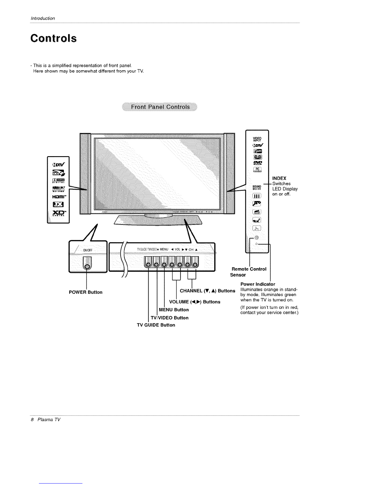
Controls ................................... 8
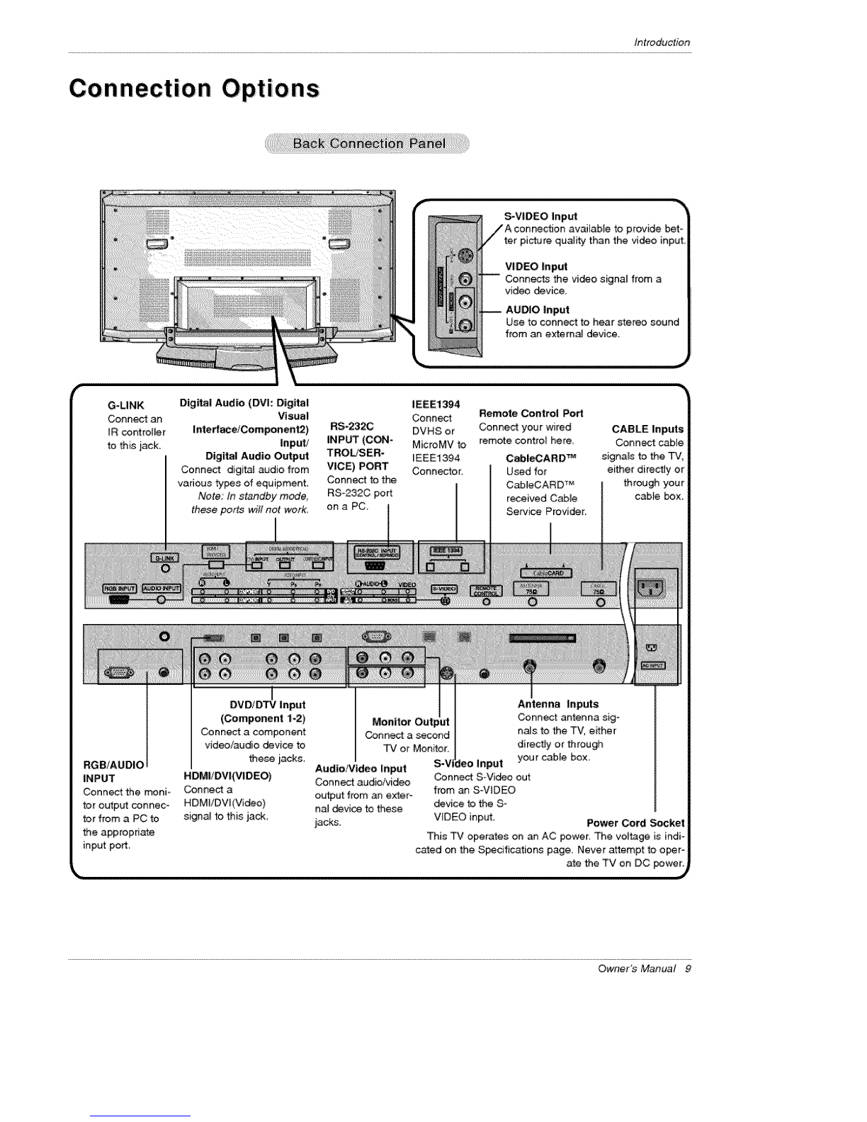
Connection Options ...................... 9,
Remote Control Key Functions ............. 10
Installation
Joining _ TV _assemb}y to _e waJ_to protect _e set _m-
b_r_j ................................. 11
Ins_lation _ns_otions ..................... 12
External Equipment Connections .......... 13_18
Antenna or C_le Connection ........... 13~14
VCR Setup
Externa_ A/V Source'Setup':::[:::::[[:::: "14,15
DVD Setup ............................ 15
Cab_eCARD _Setup ..................... 16
HDSTB Setup ........................ 16
PC Setup .......................... 17
Monitor Out Setup ...................... 18
Digital Audio Output ................... 18
HDMVDVI (VIDEO) ................... 19~21
TV Guide On Screen Setup .............. 22-31
IEEE 1394 ............................ 32~36
"IV Guide On Screen e System ............ 37~55
Operation
Screen Setup for PC mode
Adjustments for screen Posffion, Size_ and Phase ,,,56
On-screen Menus Language Selection ......... 57
Setup Menu Options
EZ Scan (Channe_ Search} .......... 58
Manual _an .......................... 58
Channel Edff ........................ 59
DTV SignaI Strength ................ 59
Channe_ _bel Setup ..................... 60
Main Picture Souse Selection .......... 60
Aux Label ............................ 60
Video Menu Options
EZ Picture ...................... 61
Manua_ Picture Contro_ (_ Option) ........ 61
Color Temperature Control ................ 61
XD ................................. 62
Video Preset ........................ 62
Audio Menu Options
Audio Language ....................... 63
EZ SoundRite /EZ Sound .................. 63
Manual Sound Contro_ (off Option) .......... 63
Front Surround ......................... 64
TV Speakers On/Off Setup ............... 64
Stereo!SAP Broadcasts Setup .......... 64
Time Menu Options
Auto Clock Setup ....................... 65
Manual Clock Setup ....................... 65
On/Off Timer Setup ..................... 65
Sleep _mer /Auto Off ....................... 66
Option Menu Features
Aspect Ratio Control ..................... 67
Cinerra Mode Setup ,67
Caption ................................. 68
Caption /Text .......................... 68
Caption Option /Demo ..................... 69
tSM Metrhod ........................... 70
Low Power ............................ 71
Split Zoom .......................... 71
Lock Menu Options
Parental Lock Setup ..................... 73
CabieCARD _' Function
Cable menu options ..................... 74
_rambled channel ...................... 74
Cable Channe_ List ...................... 75
Emer_ncy Alert Messa_ ............... 75
Remote Control
PIP (Pi_ure-in-Picture)/Twin Picture .......... 76
Watching PIP/POP/Twin Picture .............. 76
Selecting an In_ Sigr_ Source for PIP/Twin P_re..76
Swapping PiP/Twin Picture .................. 76
TV Program Sele_on for PIP ........... 76
Moving _e PIP sub picture ................ 77
Adjusting Main ara _ Pi_ Sizes for Twin Pi_, ,77
POP (Picture-out-of-Picture: Channel Scan} , ,77
Information ................................ 78
EZ Mute .................................. 79
External Control Device Setup ................... 80~84
IR Codes ................................ 85~86
Programming the Remote ...................... 87
Programming Codes ......................... 88~89
Troubleshooting Checklist ...................... 90
Maintenance ................................. 91
Product Specifications ......................... 92
Warranty ................................. 95~96
Setup and Operation, Checklist
Setup and O_ration Checklist
(see pages 11 ~ 18 for available connection and operationa_ setup options,)
1. Unpack TV and all accessories. 5. Turn video source equipment on.
2, Connect al;Iextemat video and audio equipment,
see pages 13~ 1& 6 Select viewing source for TV
See pages 60
3 lnstaJlbatteries in remote control.
See page i0.
4 Turn T'¢ on,
See page 57,
7. Fine tune source image and sound: to your personal prefer°
ence or as required by source.
See pages 6I ~ 64,
8, Additional features set up
See Contents above.
After reading: this manual, keep it handy for future reference,
6 Plasma TV
Introduction
In! U
What is a Plasma Display Panel (PDP)?
Ap_asma display paneJ is the lates_ disp[ary technology and the best way to achieve fl_ panel displays with excellent image quality
and large screen sizes th_ are easily viewab[e, _e PDP can be thought of as a descendant of the neon lamp and it can be atso
be viewed as a series of fluorescent lamps
How does it work?
PDP is an array of cedis, known _ pixeis, which are comprised of 3 sub pixe[s, c_orrespondingto the colors red, green, and blue.
Gas in a plasma state isused to react with phosphors in each sub-pixel to produce coJored Jight(red, green, or blue). These phos-
phors are the same types used in Cathode Ray Tu_ (C_) devices such as televisions and com_n computer monitors.
You get the rich, dynamic colors that you expect. Each sub-pixe[ is individu_[y controlled by advanc_ed electronics to produce over
16 mimiion different colors. A[i of this means that you _t perfect images that are e_ily viewable in a display that is less than 5
inches thick.
160 ° -Wide angle range of vision
Your ft_ pane[ p_asma screen offers an e×ception_[y broad viewing angle --over 160 degrees. This means that the dispmay is
dear _d visible to viewers anywhere in the room who can see the screen.
Wide Screen
The screen of the Plasma Disptay is so wide that your viewing experience is as if you are in a theater,
Multimedia
Connect your plasma display to a PC and you can use it for conferencing games, and _nternet browsing The Picture-imPicture
feature allows you to view your PC and video images simultaneously
Versatile
The light weight and thin size makes it easy to in_l your plasma display in a variety of locations where cenvenfJonal TVs will net
fit.
The PDP Manufacturing Process: a few minute colored dots may be present on the PDP _reen
The PDP (Plasma Display Pane_), which is the disptay device of this product: is composed of 09 to 2,2 million ceils, Afew celt
defects w[H norrr_#y occur in the PDP manufacturing proce_ Several tiny, minute co_o_ed dots visible on the screen should be
acceptable, This also occurs in other PDP manufacturers' products_ The tiny dots ap_aring does not mean that this PDP is defec-
tive, Thus a few celt defects are not sufficient cause for the PDP to be exchanged or returned, Our production technot_y mini-
mises these ceil defects during the manufa_ure and operation of this product,
Cooling Fan Noise
tn the same way that a fan is used in a PC computer to keep the CPU (Central Pr_essing Un_) coo[, the PDP is equipped with
cooffng fans to cool the Monitor and improve its reliability Therefore_ a certain [eve[ of noise could occur while the fans are operat_
ing and cooling the PDE
The fan noise doesn't have any neg_ive effect on the PDP's efficiency or reliability, The noise from these fans is normat during the
operation of this product_ We hope you unders_nd that a certain _evet of noise from the cooling fans is acceptable and is net suffi-
cient cause for the PDP to _ exchanged or returned,
Owner's Manual 7
Introduction
This is a simplified representation of front panel,
Here shown may be somewhat different from your TV,
INDEX
- Switches
LED Display
on or off.
POWER Button
Remote Control
Sensor
CHANNEL (V, A) Buttons
VOLUME (<1,1_)Buttons
MENU Button
"P,//VIDEO Button
Power indicator
Illuminates orange in stand-
by mode, illuminates green
when the TV is turned on,
(if power isn't turn on in red,
contact your service center)
TV GUIDE Sutton
8 Plasma TV
introduction
Connection Options
G-LINK
Conn_ an
IR controller
to this jack,
Digital Audio (DV|: Digital
Visual
Interf_e/Component2) Input!
Digital Audio Output
Connect digital audio from
various types of equipment.
Note: In standby mode,
these ports will not work_
S-VIDEO inputavailable to provide bet-
ter picture qual_ than the video input,
VIDEO Input
Connects the video signai from a
video device,
Use to connect to hear s_reo sound
from an externaJ device.
RS-232C
INPUT (CON-
TROLiSER-
VICE) PORT
Connect to the
RS-232C port
on a PC_
IEEE1394
Connect Remote Control Port
DVHS or Connect your wired CABLE Inputs
MicroMV to remote control here_ Connect cable
_EEE1394 Cab_AROTM signals to the TV,
Connector, Used for either directly or
CableCARDTM through your
received CabJe cable box
Service Provider.
RGB/AUDIO
INPUT
Connect the moni-
tor output connec-
tor from a PC to
the appropriate
input port.
I
DVD/DTV Input
(Component t-2)
Connect a component
video/audio device to
these iacks,
HDMIiDVI(VIDEO)
Connect a
HDMI/DVI (Video)
signaJ to this jack,
Audio/Video Input
Connect audio!video
output from an ex_er-
n_ device to these
iacks.
Antenna Inpuls
Monitor Connect antenna sig-
Connect a second rials to the TV, either
TV or Monitor directly or through
S-V Input your cable box
Conn_ S-Vi_ out
from an S-VtDEO
device to the S-
VIDEO input, Power Cord _ket
This TV operates on an AC power. The voffage is indi-
cated on the S_dfic.ations page. Never attempt to o_r°
ate the TV on DC power.
Owner's Manual 9
Ins_llatien
Remote Control Key Functions
When using the remote control, aim it at the remote control sensor on the TV.
HLuminates the remote control buttons.
TViVIDEO.\
Selects: DTV, Analog, Video_ Front Video, \
Component 1-2, RGB-DTV (or RGB-PC),
HDMI/DVl input sources.
Selects: _mponent 1-2, RGS-DTV (or RGB -
PC), HDM]/DV] input sources.
Uses to enter a program humor for multiple
program channels such as 2-1,2-2,etc
Switches the sound on or off,(Refer to p79)
Increases/decreases the sound feve]
INFO ........
When you watch the TV, information displays
on top of the screen. Not available in
Component 1-2, RG8 and HDMI/DW
mode.(Refer to p,78)
Selects MTS sound: Mono, Stereo, and SAP
in Analog mode, Change the audio language
in DTV mode
THUMSSTICK (Up/Down/Left/RightiEN_E R)
Allows you to navigate the on-_reen menus
and adjust the sy_em settings to your pref-
erence.
8rings up the main menu to the screen.
Enters or exits a Panel Menu in the TV Guide On
Screen system.
TV C
8rin_ up the TV Guide On Screen system to
the screen.
Adjusts the factory preset picture
depending on the viewing environment
Adiusts screen position, size, and
phase in PC mode
_UNi
Selects the sound appropriate
for the program"s character.
Displays the dig_aJ signa_ strength, /
FREEZE /
Freezes the currently-viewed picture, Main pic-
ture is frozen in PIP[Twin picture mode.
Installing Batteries
* Open the battery compad:m_nt cover on the back side and install the batteries
matching correct polarity (+ with +_ - with -)
, Install two 15V AA batteries Don't mix otd or used batteries with new ones.
Replace cover.
MODE
the remote operating mode: _#,
VCR, DVD_ CABLE, HDSTB or AUDIO_
Select other o_rating modes for the
remote to operate externa_ devices.
Turns your TV or any other programmed
equipment on or off, depending on mode.
(Refer to p.32-36)
SURF scroll the Surf channel
CHANNEL UP/OOWN
_]ects available channels found w_h EZ
scan
PAGE UP/PAGE DOWN
Moves from one full set of screen infor-
mation to the next one.
Changes the aspect ratio,
Select a c]os_ _ption:
Off, CC1 ~4, Text1 ~4.
Clears all on-screen displays and re_rns to
TV viewing from any menu.
Lets you select the amount of time before
your TV turns itseff off automatica[ty.
BUTTONS
Control some video cassette recorders or
DVD ptayer. ("RECORD button is net avaD
able for DVD player.)
Selects the frequency setting in the record-
ing: Once ReguBady, Weekly,
Off ('RECORD _button only)
Moves forward or backward in 24 hour
increments in the Listings G rid,
PIP
Switches bet_en PIP, POP (Picture=out-ofo
Picture) and Twin picture mode&
Switches the video win_w locking or
unlocking in the Li_ings Grid.
PI_H-IP|PCH+
Changes to next higher/lower PiP channel
PIP INPb_
Selects the input source for the sub picture,
SWAP
Exchanges the main/sub images in
P] P,q°win picture mode.
Enlarges the main picture size.
10 Plasma TV
Installation
Ensure that the following acce_ories are included with your plasma display, if an accessory, is missing, please contact the dealer
where you purchased the product
Owner's Manual Batteries Power Cord 75_ Round Cable
2-TV brackets 2-TV bracket bolts G-LINK Cable
2*WaB brackets
_cure the TV assembJy by joining it to a wail by using the TViWaH brackets,
. After the set must be mounted on the desk top, instatl the
TV brackets on the TV as shown,
Install the TV brackets on the TV as shown
insert the 2 _ff_ and tighten _urely, in the upper holes
on the bracket,
Install the wa_ brackets on the wall with 4 bolts*, (not
supplied with the product), as shown
Match the height of the TV brackets and the wall brask o
et&
Check to be st_re the brackets are tightened securely.
.Secure the TV assembly to the wall with strong strings
or wound wire cables, (not supplied with the product), as
shown
Owner's Manual 11
Installation
Installation Instructions
-The TV can be installed in various ways such as on a wall, or on a desktop etc.
* The TV is designed to be mounted horizontally: The speakers shown are optional.
, _tis recommended that DU-42PYlOX n_,3de_on_y be used at an aJtJtude of _ess than 3281 feet (lO00m) to get the best quality pic-
ture and sound.
-tt is recommen_ that DU_42PYlOXH _de[ on_y be used at an aJtJtude of less than 6561 feet (200Ore) to get the best quality pic-
ture and sound,
GROUNDING
Ensure that you connect the grounding /earth wire to prevent possibJe
electric shock, ff grounding methods are not possible, have a qualified
ele_rician install a separate circuit breaker. Do not try to ground the
unit by connecting it to telephone wires, _ightening rods, or gas pipes,
Powe_
Suppty
Short -circ u
Breaker
For proper ventilation_ allow a c_earance of 4" on each
side and 2" from the wall. Detailed installation instruc-
tions are available from your dealer, see the optional
Wall Mounting Bracket Installation and Setup The tv
guide on screen system
For proper venti_at_on, allow a ciearance of 4_on each
side and the top, 236' on the bottom, and 2" from the
wa& Detailed instai_a_on instructions are included in
the optional Desk'top Stand InstaUlation and Setup The
tv guide on screen system available from your dea_er
12 Plasma TV
Installation
Equipment Connections
1, Analog and Digital TV signals provided on antenna
Wall Antenna Socket or Outdoor Antenna without a Cable Box Connections
-For optimum picture quality, adjust antenna direction if nee_d.
_,_,_ Malti4ami_y Dweitings/Apartments
(Connect to wa_t antenna s_ket)
Wall Antenna
Bror_e Wire
2. Analog and Digital TV signals provided on cable
Cable TV Walt
Owner's Manual 13
Installation
3. Analog and Digital TV signals provided on cable and; antenna
FAntenna Bronze Wile
Turn clockwise to t_hten.
Cable TV Wall
Jack RF Coaxia_ 'Wire (75 ohm)
• in a poor signal area to improve picture quality, purchase
and instalt a signal amplifier.
• If the antenna n_ds to be split for two TV's, inst_l a "2
Way Signal Splitter" in the connections.
•if the antenna is not installed properly, contact your deah
er for assistance.
Note: The TV witt let you know when the analog, c_le, and digital channel scans are complete,
To avoid picture noise (interference), leave an adequate dist_ce between the VCR and TV
Use the ISM Method (on the Option menu) feature to avoid having a fixed image remain on the screen for a long period of time.
If the 4:3 picture format is used; the fixed irr_ages on the sides of the screen may remain visible on the screen.
Connection Option 1
Set VCR output switch to 3 or 4 and then tune
TV to the same channel number.
Connection Option 2
1. Connect the audio and video c_bies from the
VCR's output jacks to the TV input jacks, as
shown in the figure.
When connecting the TV to VCR, rr_atch the
jack colors (Video = yellow, Audio Left = white,
and Audio Right = red).
If you connect an S-VIDEO output from VCR to
the S-VIDEO input, the picture quality is
improved; compared to connecting a recjutar
VCR to the Video input.
2. insert a video ta_ into the VCR and press
PLAY on the VCR. (Refer to the VCR owner's
manual,)
3. Select the input source with using the
"P¢iV|DEO button on the remote control (If
connected to A/V INPUT, select Video input
source)
Do not connect to both Video and
S=Video at the same time,
[] []
VCR Rear
14 Plasma TV
How to connect
Connect the audio and video cabtes from the external equip-
ments outpl._ jacks to the TV input jacks, as shown in the
figure.
When _nnecting the TV to external equipment, match the
jack colors (Video = yeBow, Audio Left = white, and Audio
Right = red)_
How to uSe
1. Select the input source with using the "rViMIDEO button on
the remote control (If connected to AN INPUT, select
Video input _urce).
2. Operate the corresponding external equipment, Refer to
extema_ equipment operating the tv guide on screen system. Camcorder
Video Game Set
DVD
or
How to connect
I Connect the DVD video o_puts (Y, P& P_) to the COMPONENT (Y, PB, PR) _NPUT jacks on the TV and connect the DVD
audio outputs to the AUDIO iNPUT jacks on the TV_ as sho_ in the figure
2, If your DVD only has an S-Video output jack, connect this to the SWBDEO input on the TV and connect the DVD audio outputs
to the AUDIO INPUT jacks on the TV, as shown in the figure.
Note f If your DVD player does not have component video output, use S-Video,
How to uSe
I. Turn on the DVD player; insert a DVD.
2, Use the TMNIDEO or COMP/RGBiHDMI button on the remote controE to select Component t or Component 2. (if connected
to S-VIDEO, select the Video or Front Video extemat input _urce.)
3. Refer to the DVD pfayeCs manual for opera4Jng instructions.
, Component Input ports
To get be_er picture quality, connect a DVD pqayer to the compo-
nent inp_t ports as shown below,
l Component portson the TV
I Video output ports
on DVD p_ayer
No tes:
,Digi_lAudio will not work" for Component 1 input source.
,Digital Audio opera#on has pfiorityff Digital Audio andAUDlO L!R
are connected at the same time.
Owner's Manual 15
Installation
How to use
hsert the CableCARD r`._received from Cable Service provider to
Cab[eCARD MsJot of TV back panel.
If Host or Cab_eCARD Mdoes not display on the screen, contact with Cable
so,ice provider by phone.
Note :
.CabIeCARD _has the types of Motorol& Scientific Atlanta, SCM etc.
These 3 types of CabtaCARD _can be used for this PLASMA TV
Caution: When removing the Cab[eCARD _', do not
fa_[ it as this may _use impact to the
Cab_eCARD '_',
This TV can receive Digital Over-theo_r/Cab[e signals without an external dig[G[ set4op box. However, if you do receive Digital
signals from a digitat set4op box or other dig_taJ extemaJ device, refer to the figure as shown below.
-This TV sup_rt_ HDCP (High-bandwi_h DigifJ31 Contents Protection) protocol for Digital Contents (480p,720p,1080i).
or
Digital Set4op Box
How to connect
Use the TV's COMPONENT (Y_ PB_ P_) _NPUT, RG8 or HDM_iDV[ jack
for vi_o connections_ depending on your set4op box connector. Then,
make the corresponding audio connections
How to use
1. Turn on the digi_ set4op box. (Refer to the owner's manua_ for the
digita_ set4op box.)
2. Use TViVIDEO or COMPIRGB/HDMI on the remote control to select
Component 1, Component 2, RGB-DTV, or HDMI/DVI source.
S!cjna! Component 1/2 RGB-DTV, HDM!/DV!
480i Yes No
480£1 Yes Yes
720p Yes Yes
1080i Yes Yes
16 Plasma TV
Installation
This TV provides Plug and Play capability, meaning that the PC adjusts automaticaJ_y to the TV's settings..
- The TV perceives 640x480, 60Hz as DTV 480p based on the PC graphic card, change the screen scanning rate for the graphic
card accordingly:
How to connect
1. To get the bect picture quality; adjust the PC graphics card to 1024x768, 60Hz.
2. Use the TV's RGB iNPUT or HDMI/DVt (Digitat Visual Interface) UNPUT port for vidoo connections, de.riding on your PC con°
#ectoL
° if the graphic card on the PC does not ou_ut analog and digitaJ RGB simultaneously, connect only one of either RGB _NPUT
or DW INPUT to display the PC on the TV.
•tf the graphic card on the PC does output analog and digital RGB simuffaneousty, set the "FV to either RGB or HDMI/DVJ; (the
other mode is set to PJug and Play automaticaJly by the TV.)
3. Then, make the corresponding audio connections. If using a sound card, adjust the PC sound as required.
How to use
1. Turn on the PC and the TV.
2. Turn on the display by pressing the POWER button on the TV's remote control.
3. Select RGB-PC or HDMIiDVI input source in main input option of SETUP menu, (Refer to R59)
4. Check the image on your TV. There may be noise assod_ed with the resolution, vertical pattern, contrast or brightness in PC
_de. if noise is present, change the PC modo to another re_Jution, change the refresh rate to another rate or adjust the
brightness and contrast on the menu untif the picture is clear, ff the refresh rate of the PC graphic card can not be changed,
change the PC graphic card or consult the manufacturer of the PC graphic card.
Notes: *Depending on the graphics card. DOS mode may not work ffyou use a HDMI to DVI cable.
,'Avoid keeping a fixed image on lhe TV's screen for a long period of time. The fixed image may become permanently
imprinted on the screen. Use the Orbiter screen sever when pc_ssible.
,"The synchronization input form for Honzontal and Vertical frequencies is separate.
Monitor Display Sp_ifications (RGB-PC)
Resolution
640x350
720x400
640x480
Horizontal
Frequency{KH_
31.468
37,861
31,469
37,927
31,469
37,861
37.500
&3.269
Vertical
Frequency(H_
7&09
85.08
70,08
85,03
59.94
72.80
75.00
85.00
Resolution
800x600
1_4x768
Horizontal
Frequency(KH_
35,156
37,879
4&077
46,875
53,674
48,363
56.476
60.023
VerUcal
Frequency(Hz)
5625
6&31
72,18
75_
85._
60.00
70._
75.02
Owner's Manual 17
Ins_l/ation
Monitor Display Specifications (HDMIiDVI Mode)
Resolution
640×480
8_x600
Ho rizontal
Frequency(KHz)
31.469
37.861
37.500
35,156
37 _879
48.077
48.875
Vertical
Frequency(Hz)
59.94
72 80
75 O0
56.25
7218
75.00
Resolulion
1024x768
Horizontal
Freqaency(KHz)
48.363
56.476
60.023
Vertical
Frequency(Hz)
60.00
70.06
75.02
The TV has a special signa_ output capabiJity which allows you to
hook up a second TV or monitor.
Connect the second TV or monitor to the TV's MONITOR OUTPUT.
See the Operating ManuaJ of the second TV or monitor for further
details regarding that device's input setting&
Note
,Component_ RGB-PC/RGB-DTV. HDMI/DVL DTV input sources
cannot be used for Monitor out,
Send the TV's audio to external audio equipment (stereo system) via
the Digital Audio Output (OpticaJ) port.
How to connect
1. Connect one end of an optical cabEe to the TV Digital Audio
(OpticaO Output port
2. Connect the other end of the optica_ cable to the digital audio (op_ o
caO input on the audio equipment
& Set the "_ SpeaJt_r option - Off' in the AUDIO menu_ Refer to
page 64.
See the external audio equipment in,ruction _nua_ for operation.
Caution: Do not look into the optical output port.
Looking at the laser beam may damage
your vision
18 Plasma TV
HDMt
14_H _N_T_ON MU_M_ iNI_RF_
-HDMI '_,the HDMt logo and High-Definition Multimedia Interface are trademarks or registered trademarks of HDMI Licensing LLC."
-This TV SET can receive the High-Definition Multimedia htertace(HDMI) or {nput of DigitaI Visual lnterface(DVI).
-This TV SET sup_rts HDCP(High-bandwidth Digital Conten_ Protection) Protocel for TV SET(480p, 720p, 1080i) trades.
-When you Connect with HDMI/DW Source Devices (DVD P{ayer or Set Top Box or PC) supporting Auto HDMI/DVI function, auto-
maticaily, support Plug & Play _d then set the HDMJ/DVI Source Devices(1280 x 720p). After reading in HDMJ/DVl Source
Devices using Display Data Channel(DDC) P_otocoL EDID stored in TV SET is used. If HDMI/DVt Source Deviees not support-
ed Auto HDMf/DVI is been, the Resolution is setted, manuaJiy,
-To get the best picture quali_, adiust the DVD Player or Set Top Box output resolution to 1280 x 720p.
-To get the best picture quality; adiust the PC graphics card to 1024 x 768, 60Hz.
When Source Devices have DVl Output Connector, you must connect audio with separated cable.(Refer to .=How to connect>)
How to connect
1. When Source Devices(DVD PJayer or Set Top Box)support HDML
-If Source Devices have HDMI Output Connector, Source Devices connect to DTV with HDMI Cable .(not supplied with the prod-
uct).
- if Source Devices support Auto HDML automatically, Source Devices divert output resoiution in 1280x720p, But if not, resoiu_on
divert Manually Se_ng for reference Manual of Source Devices,
- To get the best picture quaJity, adiust the DVD Player or Set Top Box output resolution to 1280 x 7209,
- Because HDMI sends Digital Video and Audio wffh one cable, need not especia_ Audio Cable for using HDMI Cab_e,
2, When Source Devices(DVD Piayer or Set Top Box) supports DVI,
°ff Source Devices have DVl Output Connector, _urce Devices connect to DTV with HDMI to DVl Cable (not supplied with the
product).
-ff Source Devices support Auto DVL automatically, Source Devices divert output re_lution in 1280x720p. But ff not, reso{ution
divert Manually SettJng for reference Manual of Source Devices.
- To get the best picture qu_ity; adiust the DVD Player or Set Top Box output resolution to 1280 x 720p,
_n this case, Audio use other cable. When Source Devices have Fi_r Optic Digital Audio Output Connector, Digi_l Audio DVl
Input(DVt) of DTV connect to Fiber Optic DigitaJ Audio Cable (not supplied with the product) or when Source Devices have AnaJog
Audio Output Connector, RGB/DVl Audio Input of DTV connect to Audio Cable (not supplied with the product) And then you can
{isten to normat Audio,
3, When PC supports DVI,
If PC have DVf Output Connector, Source Devices connect to DTV with HDMI to DVI Cable (not supplied w_h the product),
To get the best picture quality; adiust the PC graphics card to 1024 x 768, 60Hz.
- Use the DTV's HDMVDVI(VIDEO) for video connections, depending on your PC connector.
if the graphics card on the PC does not output analog RGB and DW simuffaneousty, connect onmy one of either RGB Input or
HDMI/DW Input to display the PC on the DTV.
if he graphics card on the PC does o_put analog RGB and DW simultaneously, set the DTV to either RGB Input or HDMI!DVl
lnput;(the other mode is set to Plug and Play automatically by the DTV.)
- Then, make the corresponding audio connections, If using a sound card adjust the PC sound _ reqaired_
_n this case, Audio _se other cable, When PC (or sound card of PC) have Fiber Optic Digital Audio Output Connector, Digita_ Audio
DVl tnput(DVt) of DTV connect to Fiber Optic Digital Audio Cable (not suppiied with the product) or when PC (or seand card of
PC) have Analog Audio Output Connector, RGB1DVl Audio Input of DTV connect to Anatog Audio Cable (not supplied with the
product) And then you can listen to norma_ Audio_
Owner's Manual 19
HDMI
Cable sample
HDMI Cable
(not supplied with the product)
HDMI to DVI Cable
(not supplied with the product)
Fiber Optic Digital Audio Cable
(not supplied with the product)
Analog Audio Cable(RCA type)
(not supplied with the product)
Analog Audio Cable(Stereo to RCA type)
(not supplied with the product)
20 Plasma TV

Other manuals for DU-42PY10X

4

This manual suits for next models

1

Other LG Plasma TV manuals

LG 50PB4DA -  - 50" Plasma TV User manual

LG

LG 50PB4DA - - 50" Plasma TV User manual

LG DU-50PY10 User manual

LG

LG DU-50PY10 User manual

LG 42PJ350R User manual

LG

LG 42PJ350R User manual

LG 60PG60 - 1080p Plasma Frameless Edge HDTV User manual

LG

LG 60PG60 - 1080p Plasma Frameless Edge HDTV User manual

LG 42PG3000 User manual

LG

LG 42PG3000 User manual

LG 50PG6300 User manual

LG

LG 50PG6300 User manual

LG 60PM6700 User manual

LG

LG 60PM6700 User manual

LG 50PC1DA Series User manual

LG

LG 50PC1DA Series User manual

LG PLASMA TV User manual

LG

LG PLASMA TV User manual

LG 42PX3RV User manual

LG

LG 42PX3RV User manual

LG RT-42PX10/H User manual

LG

LG RT-42PX10/H User manual

LG PM68 series User manual

LG

LG PM68 series User manual

LG 42PG3 Series User manual

LG

LG 42PG3 Series User manual

LG 50PA4500-UF User manual

LG

LG 50PA4500-UF User manual

LG 60PN5000 User manual

LG

LG 60PN5000 User manual

LG PM67 series User manual

LG

LG PM67 series User manual

LG 42PG60UD-AA User manual

LG

LG 42PG60UD-AA User manual

LG 42PJ350 User manual

LG

LG 42PJ350 User manual

LG 50PS8000 User manual

LG

LG 50PS8000 User manual

LG PN65xx User manual

LG

LG PN65xx User manual

LG DU-42PX12XD User manual

LG

LG DU-42PX12XD User manual

LG 50PC1R Series User manual

LG

LG 50PC1R Series User manual

LG 60PZ550 User manual

LG

LG 60PZ550 User manual

LG RU-42PZ90 - Stand For 42 Inch Plasma EDTV... User manual

LG

LG RU-42PZ90 - Stand For 42 Inch Plasma EDTV... User manual

Popular Plasma TV manuals by other brands

Panasonic VIERA TH-42PV30A Specifications

Panasonic

Panasonic VIERA TH-42PV30A Specifications

Panasonic TX-PR42U10 Service manual

Panasonic

Panasonic TX-PR42U10 Service manual

JVC AV42PD20ES Service manual

JVC

JVC AV42PD20ES Service manual

Samsung PL42E7SX/RCL Service manual

Samsung

Samsung PL42E7SX/RCL Service manual

Panasonic TH-42PWD6UX operating instructions

Panasonic

Panasonic TH-42PWD6UX operating instructions

Samsung PPM42S3X Service manual

Samsung

Samsung PPM42S3X Service manual

Panasonic VIERA TC-P50G20 operating instructions

Panasonic

Panasonic VIERA TC-P50G20 operating instructions

Panasonic TH-42PA25U/P Service manual

Panasonic

Panasonic TH-42PA25U/P Service manual

Panasonic Viera TH-37PX60E operating instructions

Panasonic

Panasonic Viera TH-37PX60E operating instructions

Panasonic THC42HD18A - 42" PLASMA TV Service manual

Panasonic

Panasonic THC42HD18A - 42" PLASMA TV Service manual

Panasonic TH-65/58/50PZ750U Service hints

Panasonic

Panasonic TH-65/58/50PZ750U Service hints

Panasonic Viera TH-37PV60E Gebruiksaanwijzing

Panasonic

Panasonic Viera TH-37PV60E Gebruiksaanwijzing

Samsung PN50C540G3F Manual Del Usuario

Samsung

Samsung PN50C540G3F Manual Del Usuario

Panasonic TH-50PX60U Service manual

Panasonic

Panasonic TH-50PX60U Service manual

Panasonic Viera TH-42PZ77U operating instructions

Panasonic

Panasonic Viera TH-42PZ77U operating instructions

Panasonic Viera X50Z series operating instructions

Panasonic

Panasonic Viera X50Z series operating instructions

Samsung PS51E6505 user manual

Samsung

Samsung PS51E6505 user manual

Samsung PS43F4500AW user manual

Samsung

Samsung PS43F4500AW user manual

manuals.online logo
manuals.online logoBrands
  • About & Mission
  • Contact us
  • Privacy Policy
  • Terms and Conditions

Copyright 2025 Manuals.Online. All Rights Reserved.