1-2
GENERAL
IMPOR
IMPORT
TANT SAFETY INSTR
ANT SAFETY INSTRUCTIONS
UCTIONS
WARNING
• DISCONNECT power supply cord from
the outlet before servicing.
• Replace all panels and parts before
operating.
• RECONNECT all grounding devices.
- Failure to do so can result in severe personal
injury, death or electrical shock.
• Be sure your appliance is properly installed and grounded by
a qualified technician.
• Do not repair or replace any part of the appliance unless
specifically recommended in the manual.
All other servicing should be referred to a qualified technician.
• Always disconnect power to appliance before servicing by
removing the fuse or switching off the circuit breaker
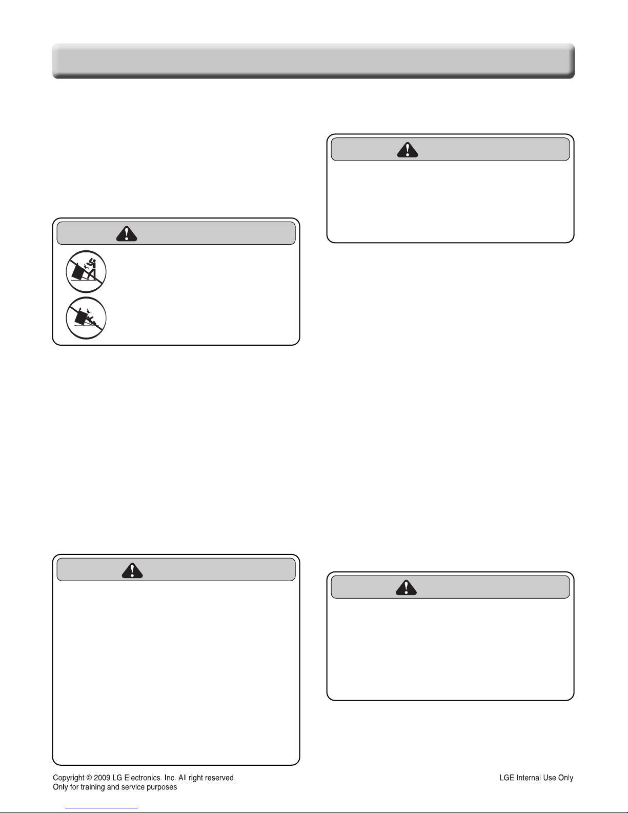
• DO NOT step or sit on the door and install the Anti-Tip
Bracket packed with range.
- The range could be tipped and injury might result from
spilled hot liquid, food, or the range itself.
- If the range is pulled away from the wall for cleaning,
service, or any other reason, ensure that the Anti-Tip
Device is properly reengaged when the range is pushed
back against the wall.
To reduce the risk of tipping of the range, the range must be
secured by properly installed anti-tip devices. To check if
the bracket is installed properly.
- Warming drawer : grasp the top rear edge of the Range
and carefully attempt to tilt it forward.
Verify that the anti-tip devices are engaged.
- Storage drawer : Remove drawer and verify leveling leg is
inserted into and fully secured by the anti-tip devices.
Refer to the installation manual for proper anti-tip bracket installation.
WARNING
• DO NOT touch burners, grates or
interior surfaces of oven.
-
Burners, grates may be hot even though they are off.
- Interior surfaces of an oven become hot enough to
cause burns.
• During and after use, do not touch, or
let clothing or other flammable
materials contact burners, grates or
interior surfaces of oven until they
have had sufficient time to cool.
-
Other surfaces of the appliance may become hot
enough to cause burns among these surfaces are
oven vent openings and surfaces near these
openings, oven doors, and windows of oven doors.
WARNING
• DO NOT store items of interest to
children in cabinets above a range or
on the back guard of a range.
- Children climbing on the range to reach items
could be seriously injured.
WARNING
• ALL RANGES CAN TIP
• INJURY TO PERSONS
COULD RESULT
• INSTALL ANTI-TIP DEVICES
PACKED WITH RANGE
• SEE INSTALLATION
• Do Not Leave Children Alone - Children should not be left
alone or unattended in area where appliance is in use. They
should never be allowed to sit or stand on any part of the
appliance.
• Never Use Your Appliance for Warming or Heating the
Room.
• Storage in or on Appliance – Flammable materials should
not be stored in an oven or near surface units. Be sure all
packing materials are removed from the appliance before
operating it. Keep plastics, clothes and paper away from parts
of the appliance that may become hot
• Wear Proper Apparel – Loose-fitting or hanging garments
should never be worn while using the appliance.
• Do Not Use Water on Grease Fires – Turn off oven to avoid
spreading the flame. Smother the fire or flame by closing the
door or use dry chemical, baking soda or foam- type
extinguisher.
• Make sure your range is properly adjusted by a qualified
service technician or installer for the type of gas (natural or
LP) that is to be used. Your range can be converted for use
with either type of gas.
• NEVER block the vents (air holes)of the range. They provide
the air inlet and outlet that are necessary for the range to
operate properly with correct combustion. Air openings are
located at the rear of the cooktop, at the top and bottom of the
oven door, and at the bottom of the range under the warming
drawer.