LG GBB530***F Series User manual

C AUTION
B E F OR E S E R VIC ING THE UNIT, R E A D THE " S A F E T Y
P R E C A UT IONS " IN THIS MA NUA L .
http://biz.lgs ervice.com
MODE L : C OL OR :
R E F R IG E R ATOR
SER VIC E MANUAL
R ef. No.R ef. No.
GBB532**** GBB531****
GBB530**** GBB539****
Ref. No.
GBF539****
Ref. No.
GBF530****

- 2 -
S AF E TY PR E C AUT IONS ....................................................................................................................................................... 2
S E R VIC ING P R E C A UTIONS ................................................................................................................................................... 3
S P E C IF IC A TIONS ................................................................................................................................................................4-7
P A R T S IDE NT IF IC A T IO N ...................................................................................................................................................8-12
INS TR UC TIONS F OR R E V E R S ING DOOR S WING ........................................................................................................13-15
DIS A S S E MB L Y .................................................................................................................................................................16-17
DOOR ................................................................................................................................................................................16
DOOR S WITC H .................................................................................................................................................................16
F AN AND F AN MOT OR .....................................................................................................................................................16
DE F R OS T C ONT R OL AS S E MBLY ...................................................................................................................................17
F R E E ZE R HE ATE R , S HE ATH ..........................................................................................................................................17
COMPRESSOR ( A + + a n d A s )ledoM+ ...................................................................................... ...................................18
PTC-STARTE R (A++ a n d A + M o d e l s ) ...................................................................................... . ..................................18
OLP ( O V E R L OAD P R O T E C T O R ) (A++ and A + M o d e l s ) ....................................................... . ..................................19
C OMP R E S S OR .................................................................................................................................................................20-28
AD J U S T M E N T .................................................................................................................................................................18-19
INVE R TE R LINE AR C OMP R E SSOR . ..........................................................................................................................20-28
HE A V Y R E P A IR ME THOD OF R E FR IG E R ATOR B Y AP P L IC ATION OF R E F R IG E R A NT ...........................................29-34
OUTLINE ....................................................................................................................... .....................................................29
HE AV Y R E P AIR S V C ME THOD ..................................................................................................................................30-34
C IR C UIT DIAG R A M ..........................................................................................................................................................35-4
TR OUB L E S HOOT ING (ME C HANIC AL P AR T) .................................................................................................................4-49
ANOTHE R E LE C TR IC C OMP ONE NT S ............................................................................................................................4
PTC AND OLP .....................................................................................................................................................................4
COMPRESSOR AND ELECTRIC COMPONENTS ......................................................................................... .........................4
S E R VIC E DIAG NOS IS C HAR T .........................................................................................................................................4
R E F R IG E R ATING C YC LE ...........................................................................................................................................4-
MIC OM FUNC TION & P C B C IR C UIT E XP L ANAT ION ....................................................................................................5-5
MIC OM E R R OR C ODE .....................................................................................................................................................5-5
P C B P IC T UR E ..................................................................................................................................................................5-6
TR OUB L E S HOOT ING WIT H E R R OR DIS P L A Y .............................................................................................................6-7
TR OUB L E S HOOT ING WIT HOUT E R R OR DIS P L AY ......................................................................................................7-8
R E F E R E NC E .....................................................................................................................................................................8-8
E XP L ODE D VIE W &R E P L AC E ME NT P A R TS L IS T ........................................................................................................8-
P leas e read the following instructions before s ervicing your
refrigerator.
1. C heck the s et for electric los ses .
2. Unplug prior to servicing to prevent electric s hock.
3. Whenever testing with power on, wear rubber gloves to
prevent electric shock.
4. If you use any kind of appliance, check regular current,
voltage and capacity.
5. D on't touc h me ta l produc ts in the fre e z e r with we t
hands. This may cause fros tbite.
6. P revent water from following onto electric elements in
the mechanical parts.
7. W hen s ta nding up a fte r ha ving c he c ke d the lowe r
s ection of the refrigerator with the upper door open,
move with care to avoid hitting the upper door.
8. When tilting the set, remove any materials on the set,
es pecially the thin plates (ex. G las s shelf or books .)
9. When s ervicing the evaporator, wear cotton gloves .
10. Lea ve the dis ass embly of the refrigerating cycle to a
s pecialized s ervice center. T he gas ins ide the circuit
may pollute the environment.
11. When you dis charge the refrigerant, wear the protective
safety glass es or goggle for eye safety.
12. When you repair the cycle s ys tem in refrigerator, the
work area is well ventilated.
E specially if the refrigerant is R 600
heat sources. (No smoking)
C ONTE NTS
S AF E TY P R E C AUT IONS

- 3 -
F ea tures of refrigera nt (R 600a)
•Achromatic and odor less gas.
•F lammable gas and the ignition (explosion) at 494°C .
•Upper/lower explosion limit: 1.8% ~8.4% /V ol.
F ea tures of the R 600a refrigerator
•C harging of 60% refrigerant compared with a R 134a model.
•The suction pressure is below 1bar (abs) during the operation.
•B ecaus e of its low s uction pressure, the external air may ow
in the cycle system when the refrigerant leak, and it caus es
malfunction in the compressor.
•T he dis pla ce ment of compressor us ing R 600a mus t be a t
leas t 1.7 times larger than that of R 134a.
•Any type of dryer is applicable (XH-5, 7, 9).
•The E VAP OR AT OR or any other cycle part that has welding
joint is hidden in the foam. (If not hidden inside, the whole
ele c tric pa rts mus t be te s te d with the L E AK A G E T E S T
according to the IE C S tandard.)
•The compressor has label of the refrigerant R 600a.
•Only the S VC man mus t have an access to the system.
After the refrigerant (R 600a) is completely dis charged,
repair any defective parts and replace the dryer. At any
cas e you must us e the LOK R ING for connecting or replacing
any part in the cycle (No F ire, No Welding). C harge the N2
gas in order to check for leakage from welding points and the
LOK R ING . If leakages are found, repair the defects again.
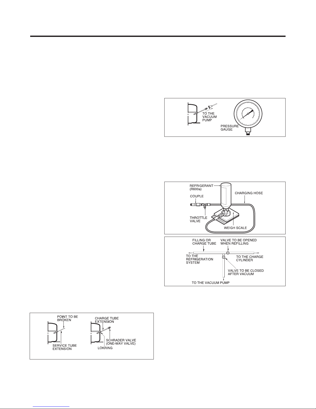
C onnect the S chrader valve to pump with the coupler. And
then turn the pump on for vacuum state (F igure 3). Let the
pump run until the low pressure gauge indicates the vacuum
(gauge pressure -1atm or -760mmHg, absolute pressure 0 ).
R ecommended vacuum time is 30 min.
After the s ys tem is completely va cuume d, ll it with the
refrigera nt R 600a up to what ha s been s pecied at your
refrigerator Name P late. T he amount of refrigerant (R 600a)
mus t be prec is ely mea s ured within the error of ±2g by an
electron scale (F igure 4).
If you us e the manifold connected with both the refrigerant
(R 600a) cylinder and the vacuum pump simultaneous ly, make
sure the pump valve is closed (F igure 5).
C onne c t the c ha r ging hos e ( tha t is c onne c te d to the
refrigerant (R 600a) cylinder) to the S chrader valve ins talled
on the s ervice tube. T hen, charge the refrigerant (R 600a) by
controlling the T hrottle valve. W hen you do s o, do not fully
open the Throttle valve because it may make damage to the
compressor. G ra dua lly cha rge the refrigerant (R 600a ) by
changing open and close the Throttle Valve (5g at each time).
The charging hose must use a one-way valve to prevent the
refrigerant reuence. C lose the S chrader valve cap after the
refrigerant (R 600a) is completely recharged.
A fte r you c omple tely re c ha rge the refrige ra nt ( R 600a ) ,
perform the leakage tes t by using a portable leakage detector
or s oa py wa te r. T e s t the low pre ssure (s uction) pa rts in
compressor o time and high pressure parts in compressor
on time. If the leakages are found, restart from the refrigerant
(R 600a) dis charging process and repairs defects of leaks .
After the leakage tes t, check the temperature of each parts of
the cycle. C heck with hands if the C ONDE NS E R a nd the
cas e (HOT -LINE pipe) that is contacted to the door gas ket
are warm. C onrm that fros t is uniform dis tributed on the
surface of the E V AP OR AT OR .
Ins tallation place
•Must be well ventilated.
•Must be 20 m3or larger.
•Must be no-s moking area.
•No ignitable factors must be pres ent.
Utilities
•R efrigerant cylinder (MAX NE T 300g)
•Manometer
•Vacuum pump (600ℓ/min)
•P iercing C lamp
•Quick coupler
•Hos es (5m-1E A, 1m-3E A)
•LO K R ING
•P ortable Leakage detector (3g/year)
•Nitrogen cylinder (for leakage tes t)
•C oncentration gauge
Make s ure before S ervicing
•R efrigerant
C onrm the refrigerant by checking Name P late and the label
on the compressor, after opening the C OVE R ASSE MB LY ,
B AC K -M/C .
•If the refrigerant is R 600a, you must not weld or apply a heat
source.
Air R echarging in C ompressor
B efore relling the re frigera nt, you mus t perform the tes t
according to C hapter 5 (T R OUB LE S HOOT ING C HAR T ). When
the de fe cts a re found, you mus t dis c ha rge the re s idua l
re frige r a nt ( R 600a ) in the outdoor. F o r dis c ha rging th e
refrigerant R 600a, break the narrow portion of tube extens ion
by hand or with a pipe cutter as shown in Figure 1. Leave it for
30min in outs ide to s tabilize the pressure with ambient. Then,
check the pressure by piercing the dryer part with piercing
pliers . If the refrigerant is not completely discharged, let the
refrigerator alone for more 30min in outs ide.
Attach the s ervice tube installed with a S chrader valve (one-
way valve) by using the LOK R ING (F igure 2). T hen, connect
the S c hra de r va lve ( one -wa y va lve ) to the pump tha t is
connected to the dis cha rging hos e le ading to the outs ide .
When dis charging the res idual refrigerant, repeat 3 cycle that
includes 3min of the pump running->pump o->30s ec of the
compressor running.
F igure 1 F igure 2
F igure 3
F igure 4
F igure 5
S E R VIC ING P R E C AUT IONS

DE F R OS T ING S YS T E M
DE F R OS TING DE V IC E
NE T W E IG HT
COOLING S YS T E M
TE MP E R ATUR E C ONT R OL
R E F R IG E R ANT WE IG HT
C O MP R E S S O R
E V AP O R AT OR
C ONDE NS E R
R E F R IG E R ATOR
C O MP AR TME NT
DO OR B AS K E T
FR E E ZE R
C OMP AR T ME NT
LU B R IC AT IO N OIL
DIME NS IONS (mm)
- 4 -
1. R ef. No: G B B530*****, G B F530*****
ITE MS
595(W) X 2010(H) X 650(D)
595(W) X 1900(H) X 650(D)
F an C ooling
Micom C ontrol
F ull Automa tic
Heater Defrost
Heater, S heath
R600a
H T S 5 5 M T
S 5 H F P
5HFP
P T C S tarting T ype
P in T ube T ype
S piral C ondenser
Wire C ondenser
R emovable G las s S helf
Vita, LE D(1E A)
C over, TV (L)
C over, TV (U)
F res h 0 Zone
Magic C ris per (1E A)
Vegetable Drawer (1E A)
Foldin g S h elf
Bott l e Rack
E gg T ray
Dairy C orner
B as ket
Water Tank
Tray Drawer (3E A)
Tray Ice
Ice B ox
Wire S helf (2E A)
•
-
-
-
3E A(option 2) 3E A(option 2)
(option )
(option )
3E A
-
G B B 530*** F*
•
••
••
••
••
••
••
•
-
•
•
••
••
••
••
••
•
•
•
•
•
••
••
••
••
-
-
-
-
-
-
- -
- -
--
-
-
3E A
3E A
-
-
-
G B B 530*** P*
67g (FLB124) 67g (FLA102)
No (FLA102/BMG089)
67g (FLA102)
61g (BMG089)
57g (BMG089)
61g (BMG089)
63g (CMA089)
61g (CMA089)
Yes(CMA089)
No (FLA102/BMG089)
Yes(CMA089)
65g (FMA102)
120cc(FMA102)
180cc(FLA102) 180cc(FLA102)
150cc(CMA089)
170cc(BMG089) 170cc(BMG089) 170cc(BMG089)
67g (FLA102)
61g (BMG089)
180cc(FLA102)
170cc(BMG089)
67g (FLA102)
61g (BMG089)
63g (CMA089)
180cc(FLA102)
150cc(CMA089)
170cc(BMG089)
150ccCMA089)
175cc(FLB124) 175cc(FLB124) 175cc(FLB124)
•
•
•
•
•
•
•
•
•
•
•
•
•
•
•
•
•
•
-
-
-
-
-
4E A
- -
-
-
GBB530*** W*
••
•
•
•
•
•
••
•
•
•
•
•
•
•
•
•
•
•
•
•
•
•
•
•
•
•
•
•
-
-
-
-
-
- -
3E A 2E A
3E A 3E A
-
•
•
•
-
G B F G B B530***X* G B B530***Z*
530*** P*
•
•
•
•
•
67g
-
•
-
•
•
•
•
•
•
•
•
•
•
•
-
-
-
2E A
3E A
•
•
•
-
G B B530***Q*
•
•
•
•
•
67g
-
-
-
- -
-
-
-
-
-
-
-
-
-
-
-
-
•
•
•
•
•
•
•
•
•
•
-
-
-
3E A
3E A
•
•
•
-
•
•
•
•
•
-
G B F530***Z*
-
-
•
•
•
•
•
•
•
•
•
•
-
-
-
3E A
3E A
•
•
•
•
-
•
•
•
•
•
S P E C IF IC ATIONS

- 5 -
1. R ef. No: G B B539*****, G B F539*****
S P E C IF IC AT IONS
DE F R OS TING S Y S T E M
DE F R OS TING DE VIC E
NE T W E IG HT
C OOLING S Y S TE M
TE MP E R ATUR E C ONT R OL
R E F R IG E R ANT WE IG HT
C O MP R E S S O R
E V AP O R AT OR
C ONDE NS E R
R E F R IG E R ATOR
C O MP AR TME NT
DO OR B AS K E T
FR E E ZE R
C OMP AR T ME NT
LU B R IC AT IO N OIL
DIME NS IONS (mm)
ITE MS
595(W) X 2010(H) X 650(D)
595(W) X 1900(H) X 650(D)
F an C ooling
Micom C ontrol
F ull Automa tic
Heater Defros t
Heater, S heath
R 600a
H T S 5 5 M T
S 5 H F P
P T C S tarting T ype
P in T ube T ype
S piral C ondenser
Wire C ondenser
R emovable G las s S helf
Vita, LE D(1E A)
C over, TV (L)
C over, TV (U)
F res h 0 Zone
Magic C ris per (1E A)
Vegetable Drawer (1E A)
Fold i ng Shelf
Bottle R ack
E gg T ray
Dairy C orner
B as ket
Water Tank
Tray Drawer (3E A)
Tray Ice
Ice B ox
Wire S helf (2E A)
•
-
-
-
2E A
(option )(option )
(option )
(option - )
(option - )
(option - )
(option 1) 2E A (option 1) 2E A (option 1) (option 1)
2E A
-
G B B 539***F*
•
••
••
••
••
••
••
•
-
•
•
••
••
••
••
••
•
•
•
•
••
••
••
••
-
-
-
-
-
(option )
•
-(option )
•
-
-
- -
- -
--
-
2E A
2E A
-
-
-
G B B 539*** P*
•
•
•
•
•
•
•
•
•
•
•
•
•
•
•
-
-
-
-
-
-
-
-
-
-
-
3E A
- -
-
G B B 539*** W*
••
•
•
•
•
•
•
••
•
•
•
•
•
•
•
•
•
•
• •
•
•
•
•
•
-
-
-
-
-
-
- -
-
-
-
-
-
-
-
-
-
-
-
-
2E A
3E A 2E A
-
•
•
•
-
G B F G B B539***F* G B B539***Z*
539*** W*
•
•
•
•
•
•
-
•
•
•
•
•
•
•
•
•
•
-
-
-
2E A (option 1)
2E A
•
•
•
-
•
•
•
•
•
67g (FLB124)
65g (FMA102)
120cc(FMA102)
175cc(FLB124)
67g (FLB124)
65g (FMA102)
120cc(FMA102)
175cc(FLB124)
67g (FLA102)
61g (BMG089)
63g (CMA089)
180cc(FLA102)
150cc(CMA089)
170cc(BMG089)
5HFP
67g (FLA102)
61g (BMG089)
180cc(FLA102)
170cc(BMG089)
No (FLA102/BMG089)
Yes(CMA089)
57g (BMG089)
61g (CMA089)
57g (BMG089)
61g (CMA089)
170cc(BMG089) 170cc(BMG089)
150ccCMA089) 150ccCMA089)

DE F R OS TING S Y S TE M
DE F R OS TING DE VIC E
NE T WE IG HT
C OOLING S Y S TE M
TE MP E R AT UR E C ONT R OL
R E F R IG E R ANT WE IG HT
C OMP R E S S OR
E V AP OR AT OR
C ONDE NS E R
R E F R IG E R AT OR
C OMP AR TME NT
DO OR B AS K E T
F R EEZE R
C OMP AR TME NT
LU B R IC AT IO N OIL
DIME NS IONS (mm)
- 6 -
1. R ef. No: G B B539*****, G B F539*****
ITE MS
595(W) X 2010(H) X 650(D)
595(W) X 1900(H) X 650(D)
F an C ooling
Micom C ontrol
F ull Automa tic
Heater Defrost
Heater, S heath
R 600a
P T C S tarting T ype
P in T ube T ype
S piral C ondens er
Wire C ondenser
R emovable G lass S helf
Vita, LE D(1E A)
C over, TV (L)
C over, TV (U)
F res h 0 Zone
Magic C ris per (1E A)
Vegetable Drawer (1E A)
E gg T ray
Dairy C orner
B as ket
Water Tank
Tray Drawer (3E A)
Tray Ice
Ice B ox
Wire S helf (2E A)
-
-
-
3E A
3E A
-
- -
G B B539**HW*
••
••
••
••
••
••
•
••
••
••
••
••
••
••
••
-
-
-
-
-
-
-
-
-
-
- -
-
-
3E A
3E A
-
-
-
GGBB539**HZ*
BB539**HP*
63g
-
•
•
•
•
•
•
•
•
•
•
•
•
•
•
•
-
-
-
-
-
-
-
-
-
3E A
3E A
-
-
67g
S5 H F P
S P E C IF IC AT IONS
57g (BMG089)
61g (CMA089)
170cc(BMG089)
150cc(CMA089)
5HFP

DE F R OS TING S Y S T E M
DE F R OS TING DE VIC E
NE T WE IG HT
C OOLING S Y S TE M
TE MP E R AT UR E C ONT R OL
R E F R IG E R ANT WE IG HT
C OMP R E S S OR
E V AP OR AT OR
C ONDE NS E R
R E F R IG E R AT OR
C OMP AR TME NT
DO OR B AS K E T
F R E E ZE R
C OMP AR TME NT
LU B R IC AT IO N OIL
DIME NS IONS (mm)
- 7 -
1. R ef. No: G B B530***M*, G B F539***M*
ITE MS
595(W) X 2010(H) X 650(D)
595(W) X 1900(H) X 650(D)
F an C ooling
Micom C ontrol
F ull Automa tic
Heater Defrost
Heater, S heath
R600a
HTS55M T
P T C S tarting T ype
P in T ube T ype
S piral C ondens er
Wire C ondenser
R emovable G las s S helf
Vita, LE D(1E A)
C over, TV (L)
C over, TV (U)
F res h 0 Zone
Magic C ris per (1E A)
Vegetable Drawer (1E A)
Fold ing Shelf
Bottel Rack
E gg T ray
Dairy C orner
B as ket
Water Tank
Tray Drawer (3E A)
Tray Ice
Ice B ox
Wire S helf (2E A)
-
-
- -
-
3E A
3E A
-
G B B530**QM*
•
•
••
••
••
••
••
••
••
••
•
• •
•
•
•
•
•
•
••
•
•
• •
•
••
•
••
•
-
-
-
-
--
170cc 170cc
-
2E A
2E A
-
-
-
G B B 539**QM*
61g 61g
S 5 H FP (5CST)
S P E C IF IC ATIONS

- 8 -
G B B530****
Model Name : GBB530**Q**, GBB530**C**
P A RTS I D E N T I F ICATION
Lamp
Removable
Glass Shelf
Removable
Glass Shelf
(Folding shelf
Optional)
Vegetable
Drawer (Used to
keep fruits and
vegetables etc.
fresh and crisper)
Fresh '0' Zone
(Optional)
Ice Tray
Wire Shelf
Freezer
Compartment
Leveling Screw
Basket Door
Basket Door
Bottle Rack
(Optional)
Dairy Corner
(Optional)
Egg Tray (Optional)
EZ Open
Handle
(Optional)

- 9-
G B B530*****
Model Name : GBF530**Q**
P A R T S I D E N T I F I C ATIO N
Lamp
Removable
Glass Shelf
Vegetable
Drawer (Used to
keep fruits and
vegetables etc.
fresh and crisper)
Fresh '0' Zone
(Optional)
Ice Tray
Wire Shelf
Freezer
Compartment
Leveling Screw
Basket Door
Water Tank
(Optional)
Basket Door
Dairy Corner
(Optional)
Egg Tray (Optional)
EZ Open
Handle
(Optional)
Bottle Rack
(Optional)
Removable
Glass Shelf
(Folding shelf
Optional)

- 10 -
G B B539*****
Model Name : GBB539**QF*, GBB539**QP*, GBB539**CF*, GBB539**CP*, GBB539**CZ*, GBB539**QZ*
P A R T S ID E NTI F I C A T I O N
Lamp
Removable
Glass Shelf
Vegetable
Drawer (Used to
keep fruits and
vegetables etc.
fresh and crisper)
Fresh '0' Zone
(Optional)
Freezer
Compartment
Leveling Screw
Basket Door
Basket Door
Dairy Corner
(Optional)
Egg Tray (Optional)
Ice Tray
Wire Shelf
EZ Open
Handle
(Optional)
Bottle Rack
(Optional)
Removable
Glass Shelf
(Folding shelf
Optional)

- 11-
G B B539****
Model Name : GBB539**QW*, GBB539**HW*
P A R T S ID E NTI F I C A T I O N
Lamp
Removable
Glass Shelf
Removable
Glass Shelf
Vegetable
Drawer (Used to
keep fruits and
vegetables etc.
fresh and crisper)
Ice Tray
Wire Shelf
(Optional)
Freezer
Compartment
Leveling Screw
Basket Door
Basket Door
EZ Open
Handle
(Optional)
Egg Tray (Optional)
Removable
Glass Shelf
(Folding shelf
Optional)

- 12-
G B B539****
Model Name : GBF539***W*
P A R T S I D E NTI F I C A TIO N
Lamp
Removable
Glass Shelf
Vegetable
Drawer (Used to
keep fruits and
vegetables etc.
fresh and crisper)
Ice Tray
Wire Shelf
Freezer
Compartment
Leveling Screw
EZ Open
Handle
(Optional)
Basket Door
Water Tank
(Optional)
Basket Door
Egg Tray (Optional)

- 13-
INS TR UC TIONS F OR R E VE R S ING DOOR S WING
This refrigerator allows the owner to change the door swing if desired. T he hinging of the doors can be changed
to the opposite s ide anytime you wish.
When revers ing the door s wing :
R ead the ins tructions all the way through before s tarting.
·Handle parts carefully to avoid s cratching paint.
·S et screws down by their related parts to avoid us ing them in the wrong places.
·P rovide a non-s cratching work surface for the doors .
IMP OR TA NT
Once you begin, do not move the cabinet until door-swing revers al is completed.
These instructions are for changing the hinges from the right side to the left side-if you ever want to change the hinges back
to the right side, follow these same instructions and reverse all references to left and right.
B efor R emoving the Doors , empty and R emove all the Door B as kets of both R efrigerator/F reezer Doors , including the B ank
Dairy. C lose both doors before removing hinge pins.
C aution :
Do not let either door drop to the oor. Doing so could damage the Door S top.
Warning E lectric S hoc k Hazard
Dis connect electrical supply to refrigerator before installing. F ailure to do so could result in death or s erious injury.

- 14-
1) R emove s crews(3) after removing a C AP (2) from the side
of the refrigerator room HANDLE (1).
The freezer room HANDLE (5) may be also disassembled in
a s ame may as the refrigerator room HANDLE (1). (2)
(4)
(4)
(1)
(5)
(3)
(2)
(3)
2) R emove the s crews(6) in the DE C O C OVE R (7).
R emove the DE C O C OV E R (7) and move the C OVE R
HING E (8) to side of DE C O C OV E R (7). Disassemble the
Hous ing C onnector(9) inside of the DE C O C OVE R (7).
3) R emove the s crews(10) in the C OV E R -P W B (11), and
remove the COVE R -P WB (11).
4) R emove the s crews(12) in the T OP C O VE R F R O NT (13)
and remove the TOP C OVE R F R ONT (13).
5) R emove the HOLDE R C OR D (14) placed in right and insert
it to center. And then move C OV E R F R O NT (16).
Take out the HOLDE R C OR D(s pare) (15) and to place in
the center of T OP C OV E R F R O NT (13), and insert to the
left side.
INS TR UC TIONS F OR R E VE R S ING DOOR S WING

- 15-
6) Take out the LEAD WIRE(17) assembly from the TOP
COVER FRONT(13) and assemble it on the left side.
7) Remove bolts(18) securing HINGE-U(19).
Uns crew of the hinge pin(20).
Place HINGE-U and seat hinge upside down and apply
them to left side of the refrigerator.
NOTE:
Seat hinge to be placed under the HINGEU(19).
8) Remove bolts(22) securing HINGEC(23) and then remove
HINGE-C(23).
Remove the freezer door. Move in left side of the
refrigerator CAP(24). Move to left side of the refrigerator
door BRACKET DOOR (25) and screw (26).
10) Assemble:
HINGE -L F reezer Door HINGE -C (23) R efrigerator Door
HINGE -U(19) T OP C OVE R FR ONT (13) C OV E R P WB (11)
C onnect the Hous ing C onnector(9) DE C O C OVE R (7) HANDLE (1) (5)
11) Remove Freezer and Refrigerator Door Gaskets and turn them 180˚.
Assemble them again and put some lubricant onto their surface.
9) Remove Bolts(27), HINGE-L (28), STOPPER (29), (30) and
Lavel(31).
Use the new HINGE-L in Drawer and attach a label to a
screw Hole.
(29)
(30)
(32)
(27)
INS TR UC TIONS F OR R E V E R S ING DOOR S WING
G AS K E T
LUBRICANT
NOTE:
Reversing the doors is not covered by the warranty.

- 16-
Figure 11
SHROUD
MOTOR DAMPER
SENSOR
GRILLE, FAN
BRACKET,
MOTOR FAN
3. FAN AND FAN MOTOR
1) Remove all of the freezer compartment,
(Involved wire shelf, ice maker)
2) Pull out the Grille Fan and Shroud F.
3) Disconnect the Housing of lead wire.
4) Remove three screws in Grille Fan.
5) Separate Shroud, F to the Grille Fan.
6) Loose three screws xed to the Bracket.
7) Pull out Bracket and then remove the Fan Motor
Assembly.
* Fan Motor Assembly can’t separate.
1. DOOR
•Freezer Door
1) Refer to previous chapter "Instruction for Reversing
Door Swing".
2) P ull out Door Gasket to remover from the Door
Foam Assembly, F .
2. DOOR SWITCH
1) Unplug the power cord from the outlet.
2) Loosen s ix screws in upper part and disconnect Top
Cover Front.
3) Disconnect Lead Wire from switch.
4) Disengage hook behind the switch by pressing it with
hands.
•Refrigerator Door
1) Refer to previous chapter "Instruction for Reversing
Door Swing".
2) Pull out the Door Gasket to remove from the Door
Foam Assembly, R .
G AS K E T
F igure 7
F igure 9
DI S A SSEMBL Y

- 17-
4. DE FR OS T C ONT R OL A SSE MB LY
Defros t C ontrol Assembly cons is ts of T hermis tor a nd F us e,
Melting. Thermistor functions to defrost automatically and it
is attached to metal side of the E vaporator and senses
temperature.
F us e, Melting is a kind of s afety device for preventing
overheating of the Heater when defrosting.
At the temperature of 77˚C , it stops the emission of heat
from the Heater.
1) P ull out the S hroud, F after removing the G rille.
- F reezer
P ull out the G rille. - F ridge
2) S eparate the connector connected with the Defrost
C ontrol Assembly and replace new one.
F igure 12
F us e, Melting
5. F R EEZE R HE AT E R , S HE AT H
In this refrigerator, Heater, S heath is us ed for defros ting
heater. During heating, the temperature of heater ris es
about 300~350˚C . Therefore, be careful not to burn while
servicing.
1) After removing the G rille and S hroud, separate the
Heater, S heath by disconnecting the connectors .
2) E xchanged Heater, S heath and connected the housing.
F igure 13
Heater, S heath
Thermistor
DI S A SSE M B L Y

- 18-
ADJUSTMENT
1. COMPRESSOR (In A++ and A+ Models)
1) Role
The compres sor intakes low temperature and low pres s ure
gas evaporated from E vaporator of the R efrigerator, and
condens es this gas to high temperature and high pres s ure
gas , and then plays delivering role to C ondenser.
2. PTC-STARTER (In A++ and A+ Models)
1) Composition of PTC-Starter
semiconductor s tarting device which us es ceramic
material and this material consists of B aTiO3.
(2) The higher the temperature is, the higher becomes the
resistance value. T hes e features are used as starting
device for the Motor.
2) Role of PTC-Starter
(1) P TC is attached to Hermetic C ompres sor us ed for
R efrigerator, S how C ase and starts Motor.
(2) C ompressor for hous ehold refrigerator applies to
single-phase induction Motor.
F or normal operation of the s ingle-phas e induction
and s ub-coil. After the starting is over, the current in
the above roles . S o, P T C is us ed as a motor starting
device.
2) Composition
The C ompressor is C ompos ed of C ompres sor Apparatus
compres sing gas , C ompressor Motor moving C ompres sor
Apparatus and C as e protecting C ompress or Apparatus
and Motor. T here is R elay Assembly (one set of
P T C S tarter and Over Load P rotector (OLP )) in
C ompres s or. On the other hand, becaus e the C ompressor
consists of 1/1000mm processing precision components
and is s ealed after production in absence of dust or
humidity, deal and repair with care.
3) Note for Usage
(1) Be careful not to allow over-voltage and over-current.
(2) No S trike
If applying forcible power or s trike (dropping or careless
dealing), poor operation and nois e may occur.
(3) Use proper electric components appropriate to the
C ompres sor.
(4) Note to K eep C ompres sor.
If C ompres s or gets wet in the rain and rust in the pin of
Hermetic Terminal, the res ult may be poor operation
and poor contact may caus e.
ssor inside in replacing the
C ompres s
noise.
3) PTC-Applied Circuit Diagram
•According to S tarting Method for the Motor
Figure 9
4) Motor Restarting and PTC Cooling
C ompres s or Motor operation, plug the power cord after
5 min. for pres s ure balance of R efrigerating C ycle and
P T C cooling.
(2) During normal operation of the C ompres s or Motor, P T C
elements generate heat continuous ly. T herefore, if P TC
isn't cooled for a while after the power has been shut
5) Relation of PTC-Starter and OLP
ssor and
the power is on before the P TC is cooled, (instant
misconnecting), the P T C isn't cooled and a res is tance
value grows. As a result, curr
subcoil and the Motor can't operate and the OLP
rrent in only in the
main-coil.
times , P T C is cooled and C ompres sor Motor performs
normal operation.
If OLP does n't operate when P T C is not cooled,
C ompres sor Motor is worn away and causes
OLP without fail.
6) Note to Use PTC-Starter
(1) Be careful not to allow over-voltage and over-current.
(2) No S trike
Don't apply a forcible power or s trike.
(3) K eep apart from any liquid.
If liquid such as oil or water away enter the P T C , P T C
materials it may break due to insulation breakdown of
the material itself.
(4) Don't change P TC at your convenience.
Don't disas s emble P TC and mold. If the exterior to the
P TC -s tarter is damaged, res istance value is altered
and it may cause poor starting of the compressor motor
may cause.
OV E R LOAD
P R OT E C T OR (O .L .P )
R E LAY AS S E MB LY
P T C S T AR T E R
R S IR
HE R ME T IC
TE R MINAL
C OMP R E S S O R
MOTOR

- 19-
3. OLP (OVER LOAD PROTECTOR)
(In A++ and A+ Models)
1) Denition of OLP
(1) OLP (O V E R L OAD P R O T E C T O R ) is a ttached to the
H erme tic C ompre s s or a nd protec ts the Motor by
cutt rrent in C ompressor Motor in case of over-
rising temperature by Bimetal in the OLP .
ssor motor, the
B imetal works by heating the heater inside the OLP ,
and the OLP protects Motor by cutt rrent which
ssor Motor.
2) Role of the OLP
(1) T he OLP is attached to the Hermetic C ompres sor us ed
for the R efrigerator and S how C ase and prevents the
Motor C oil from being s tarted in the C ompressor.
(2) Do not turn the Adjust S crew of the OLP in any way for
normal operation of the OLP .
(C ompos ition and connection Diagram of OLP )
C ONT AC T ING
P OINT C OV E R
B IME T AL
B IME T AL
HE AT E R
HE AT E R
TE R MINALS
ADJ US T
S C R E W
C ONT AC T ING
P OINT
Figure 20
ADJUSTMENT

- 20 -
COMPRESSOR
1. Inverter Linear Compressor
1) Method to Measure Compressor Winding Resistance
Normal Determination Criteria.
The compressor winding resistance can be determined as normal if resistance values show the values as described in
below gure when measuring resistance values of the harness (connected with compressor) to connect.
Connect201(CON201) of the main PWB as shown in below gure.
Check for defect of the inverter linear compressor in following orders:
Defect Determination Criteria
•Check connection status of the Compressor Connection Harness-P(Lead Wire) which is located at the M/C room where
resistance values measured at the CON201 Housing are shown as innite or several hundred MΩ . Separate connecting
wires of the M/C room (A-point in Figure) and then measure resistance values at the connecting wires again. The
compressor can be determined as normal if resistance values are shown as standard resistance value. Check connection
status of a harness.
Defect at M/C room connection contact or CON201 Housing contact, short-circuit of harness)
•Where resistance values measured at A-point are also shown as innite or several hundred MΩ , disassemble a cover PTC
of the compressor terminal and check the terminal connecting status at the B-point in Figure.
•Where there is no failure in the wiring status and resistance values are shown as innite or several hundred MΩ , it may be
determined as defect of compressor.
•Since if there is no failure in resistance values of the compressor, it may be defective Main PWB, replace the Main PCB
and check for normal operation of the compressor.
•When determining any defect through resistance measuring, it can be determined as normal if resistance values show as
descried in the below gure by measuring ①power and ③common terminal or ②full power and ③common terminal.
However, resistance values are measured when measuring ①power and ②full but measuring is meaningless since they
cannot become criteria for determining defect (measuring not required).
Caution
1. Be sure to powering o the refrigerator and measure after several minutes has passed.
2. If not accurately measuring resistance, wrong determination may be guided. (Dierence of resistance value of several W
or so may occur.)
Multi
Tester
CON201 Multi
Tester
Po : Power
Co : Common
N/C : Open terminal
Po N/C
Co
Multi
Tester
Multi
Tester
Because of ambient temperature or operating situations;
the values shown can have a slight devlation.
Earth
Hermetic terminal
Dead Short Check
Resistance
10 ~ 12 Ω
FLA102NAMA
OLP
This manual suits for next models
20
Table of contents
Other LG Refrigerator manuals

LG
LG LMXS307*6S Series User manual

LG
LG LTN19312 Series User manual

LG
LG LFC22760 Series User manual

LG
LG LSC 26905TT User manual

LG
LG LFD21870 Series Instruction Manual

LG
LG G B352C Series User manual

LG
LG LFXC24726S/03 User manual

LG
LG LFX25973SW.ASWCNA0 User manual

LG
LG LCF1153BBSL User manual

LG
LG LT22CBBSLN.APZGNGH User manual