LG GR-P247C User manual

GR-P247C
REFRIGERATOR
SERVICE MANUAL
GR-L247C

2
Table of Contents
Chapter 1 Safety Warning and Cautions ........................................................................................ 3
Chapter 2 Product Standards ......................................................................................................... 8
Chapter 3 Circuit Diagram ............................................................................................................... 9
Chapter 4 Appearance Size of Refrigerator and Name of Every Part ....................................... 10
1. Appearance Size of Refrigerator .................................................................................................. 10
2. Main Name ................................................................................................................................... 11
3. Flower Lamp Operation (Applicable to some models only) ......................................................... 12
Chapter 5 Micom Function ............................................................................................................ 13
1. Operation Panel Figure ................................................................................................................ 13
2. Description of Function ................................................................................................................ 13
Chapter 6 Explanation of Micom Circuit ...................................................................................... 20
1. Explanation of PWB Circuit .......................................................................................................... 20
2. Sensor Resistance Characteristics Table .................................................................................... 25
3. Door open Detection Circuit ......................................................................................................... 36
4. PWB Circuit Diagram ................................................................................................................... 39
Chapter 7 Operation Principle and Repair Method of Ice Maker & Dispenser ......................... 41
1. Operation Principle ...................................................................................................................... 41
2. Function of Ice Maker .................................................................................................................. 42
3. Diagnosis of Ice Maker & Failure ................................................................................................. 45
4. Circuit Part of Ice Maker .............................................................................................................. 46
Chapter 8 Compressor .................................................................................................................. 47
1. Inverter Linear Compressor ......................................................................................................... 47
Chapter 9 Heavy Repair Method of Refrigerator Applying R600a Refrigerant ........................ 51
1. Outline .......................................................................................................................................... 51
2. Heavy Repair SVC Method .......................................................................................................... 52
EXPLODED VIEW ........................................................................................................................... 58

3
Safety Warning and Cautions
▶Cautions for safety’ should be observed since they are for previously prevent accidents and dangers when
properly use or repair products in a safe manner.
▶Cautions are classified into ‘Warning’ and ‘Caution’ and meaning of them are as follows
Warning
Warning Warning means symbol to inform any accidents that may result in large danger
such as death or severe injury, etc when violating instructions.
Caution Caution means symbol to inform any accidents that may result in injury or
physical damage of houses or furniture, etc when violating instructions.
Be cautious of electric shock.
Control board (PWB Main and Sub)
uses power supply of about 310V.
Check that power plugs are not
pressed by the rear side of
refrigerator.
Damage of power plugs
could result in fire or
electric shock.
Use dedicate socket for power
socket.
Inserting various products into
a power socket at the same time
for use could result in fire due to
overheat of the socket part.
Do not allow consumers to directly
repair, disassemble or modify
refrigerator.
Harm, electric shock
or fire could occur.
Chapter 1 Safety Warning and Cautions
Be cautions of air ventilation in case of repairing refrigerator
cycle.
Remove heat source or fire appliance for working since R600a refrigerant is
inflammable. (Absolute no-smoking)

4
Safety warnings and cautions
Warning
If grounding is required, be sure to
perform grounding.
Be sure to
perform grounding
if deemed there is
danger of electric
shock by water or
moisture.
Grounding nut
Grounding wire
More than
75cm
Copper
plate
Do not allow to restore
inflammable ether, benzene,
alcohol, chemical drugs, LP gas,
etc in a refrigerator.
There is danger of
explosion and fire.
EtherBenzene
Chemical
drugs
LP gas
Don allow to keep drugs or
academic data, etc in a refrigerator.
in change of quality
or danger due to
unexpected
reaction.
Inputting products requiring strict
temperature control may result
When getting refrigerator away,
remove its door and do
not leave refrigerator
at a place where
children play.
If children go in it
and are entrapped in
it, it is dangerous.
Take power plugs from socket for
cleaning or repair.
In addition, plug out or plug in
with the wet hands.
Electric shock or
harm may occur.
Firstly take power socket out for
Electric shock may occur.
Check that dusts are adhered to
the power socket and securely
insert plugs by the end of pin so
that shaking may not occur.
Dust or incomplete
connection may
result in fire.
When dusts etc are stained to the
pin part of the power socket,
cleanly wipe out them.
Fire may occur.

5
Safety warnings and cautions
Warning
Expand or modify length of power
plugs to use.
Electric shock or
fire may occur
due to electrical
damage of power
cables.
Do not place heavy objects on a
refrigerator.
Dropping of objects
when opening or closing
doors may injury.
Do not hang to the door of a
refrigerator.
The refrigerator may
upset or the hands may
be held between doors
and damaged. Especially,
be cautious of children.
Do not use an inflammable spray
near a refrigerator.
There is danger of fire since
it is inflammable material.
Leave fire appliances at a remote
location.
There is danger of fire.
Do not touch a refrigerator or
socket when gas leaks and open
the door for ventilation.
There is danger of
burning due to
explosion and
sparking.
Do not spray inside or outside of
the refrigerator.
Bad insulation of
electrical part may
result in electric
shock or fire.
Do not use a refrigerator for other
purpose than for home purpose
(keeping of medical drugs or
experimental materials,
for vessel)
Unexpected danger
such as fire, electric
shock or deterioration
of objects kept.
Always use inundated
refrigerator after service.
Electric shock or fire may occur.

6
Safety warnings and cautions
Caution
Do put the vessel that flower base,
cup, cosmetics or drugs, etc
are contained on the
refrigerator.
Fire or electric shock may occur, or
injury due to dropping may occur.
Do not accumulate objects on a
refrigerator or do not keep
foods in random method.
Dropping of objects when opening
or closing the door may cause
physical injury.
Do not put bottles, etc in the
freezing room.
There is injury danger due to
icing and breaking of
contents.
Be sure to rated parts for
replacement of electric parts.
Check marking of model, rated voltage, rated
current, operation temperature, etc of
electrical parts.
Accurately arrange wiring of the
housing part for failure repair.
Check that the hanging
part of the housing part
is firmly suspended.
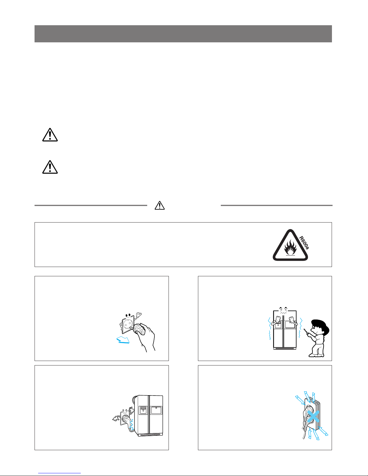
Do not damage, process or forcedly
bend, take out or twist power cords.
Damage of power cords may
cause fire or electric shock.
Entirely remove dusts or foreign
materials from housing part, wiring
part and checking part, etc for
failure repair.
Danger of fire can be
prevented from tracking, short, etc.
Check assembling status of parts
after failure repair.
Parts should show same status
before repair.
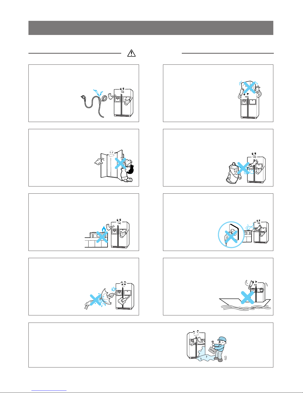
Check that there is a track that
moisture is penetrated into electric
parts.
If there is a track that moisture is penetrated,
replace parts or take a necessary step such
as insulation tapping.
Insert power plug into a socket
after more than 5 minutes pass
when taking out plugs and
then inserting them again.
Unreasonable operation of a
compressor may cause failure.
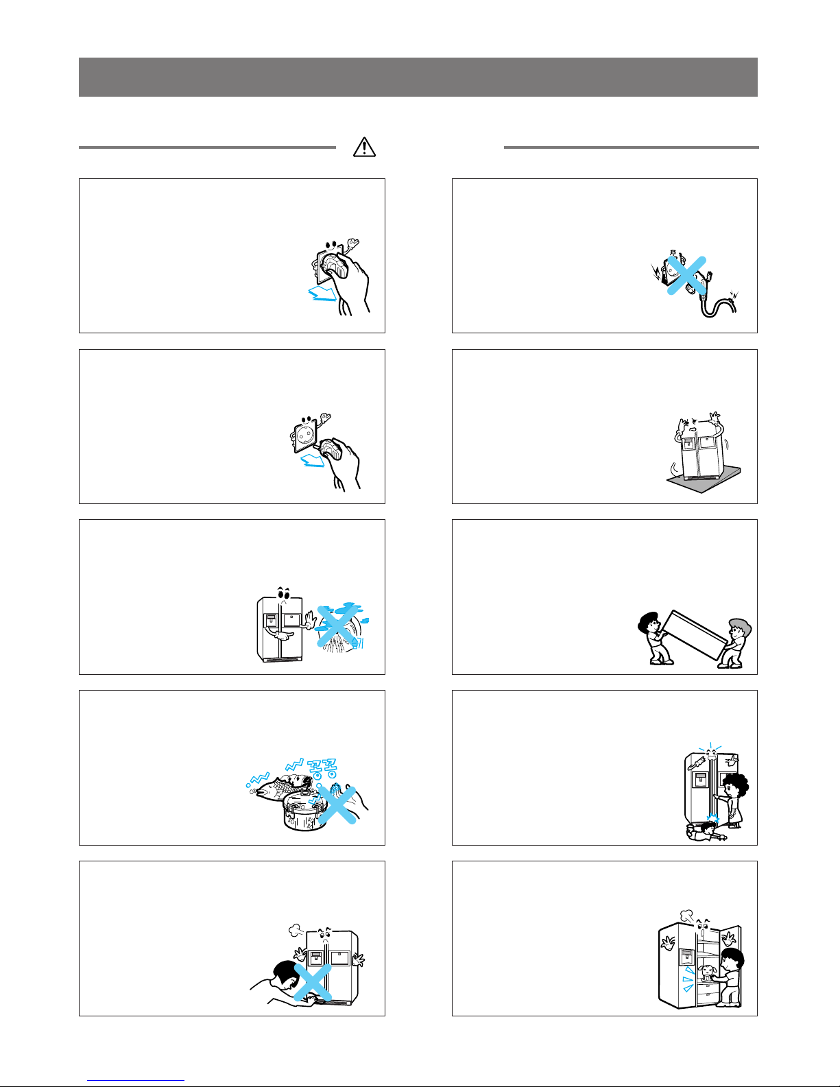
Do not put the hands or tools, etc into the
ice discharging outlet to check proper
operation of the ice feeding motor.
Damage of parts or injury of the hands may occur.

7
Safety warnings and cautions
Caution
power plugs catching with the end
of plugs without catching cords.
Fire may occur due to electric
shock or short-circuit.
Do not use power cords or power
plugs when they are damaged or
holes of power plugs are loose.
Fire may occur due to
electric shock or
short-circuit.
Take power plugs from the socket
when not using them for a long
time.
Electric shock, electrical
leakage or fire may occur
due to weaken insulation.
Do not install the product at the
place where the floor is strong and
horizontal.
If installing the product at
unstable place, the refrigerator
may upset due to closing or
opening of doors of refrigerator
and user may be damaged.
Do not install product at a place
with much moisture and where
water spatters.
Deterioration of insulation
may cause electrical
leakage.
Transport product catching with
handles on the bottom side and
the top side when transporting.
damaged since the hands
are slipped. Danger of fire
can be prevented from
tracking, short, etc.
If not catching with handles, you can be
Do not touch foods or vessels
(made of metal) in the freezing
room with the wet hands.
You may be frostbitten.
Be caution since a person near the
refrigerator may be damaged when
opening or closing the doors.
Be cautious since the hands or
foots are lay between door gaps
and children beside the doors may
be damaged by the corners of
product.
Do not put the hands under tha
bottom of the refrigerator.
The bottom side of the
refrigerator is made of
iron plate and so you
may be damaged.
Do not put live animals in the
refrigerator.

8
Product Standards
Chapter 2 Product Standards
617
205
412
910 X 788 X 1785
AC220~240/50~60Hz
135
90 ±15%[W]
200 ±15%[W]
160 ±15%[W]
Indirect cooling(F/R Control)
Micom(Outside)
Micom(Outside)
Forced method
Auto
Auto
Forced method
Cyclo-Pentane
4
1
1
-
2
3
1
1
2
IPM operation
Pin tube type
Forced convection method
HTS60MT(190 cc)
R600a(75 g)
0.85
0.9
MOLECULAR SIEVE XH-9
4~5 hours (vary depending on condition)
9~11hours (vary depending on condition)
F-Room: 3Min, R-Room: 5Min
F-Room: 5℃, R-Room: Returned to defrost function when reaching to 10℃
250/72℃
AC240V (F-Room:200W, R-Room:150W)
-
DC 12V/0.5W
AC220V / 4.3W
-
AC230V / 8W
DC 0.8W
MRA12300-9201
DC 13V
DC 14V
12V / 8.7W
12V / 8.7W
250V/0.5A
250V/0.5A
250V/9A
12.25 ㎟
DC 12V
230V~240V 50Hz
20RPM
240V/50Hz
DC12V
220V~240V/50~60Hz
DC12V
Effective inner
capacity
Heater
Rated consumption power
Temperature control
Defrost
F-Room
R-Room
F-Room
R-Room
F-Room
R-Room
Method
Start
End
Evaporation
Type of heat shield
Shelf
Auto door ice-maker
door ice-maker
-35℃special R-Room
Fixed drawer
Shelf
Egg container
Vacuum shielding vegetable room
Vegetable room
Outer dimension (W x D x H)
Rated voltage and frequency
Product weight (kg)
Rated consumption power of motor
Cooling method
Total inner capacity(L)
F-Room
R-Room
GR-P247C
Model Name
Divison
Freezing cycle
Electrical
parts
standard
Ice and water
dispenser
Compressor driving method
Evaporator
Condenser
F-Room oil
Type of refrigerant
Dryer (drying tube)
Overload protective device
Cold/freezing fan motor
Fan motor for cooling condenser
Inside lamp at F-Room
Inside lamp at R-Room
Flower lamp switch
Door switch (F-Room/R-Room)
Home bar door switch
Flower lamp
Main Fuse
Power cord
Icemaker unit
Ice feeding and clashing motor
(Motor, Geared)
Solenoid cube
Duct door Motor
Water Valve
Pump(Option)
Capillary tube
Product
-related parts
Parts related
with dewing
prevention
For preventing
ice making
F-Room
R-Room
Initial defrost
Defrost cycle
Rest time
Defrost sensor
Temp. fuse (rated/ operation temperature)
Heater sheath
Dispenser duct door heater
Chute heater
R-Room home bar heater
F-Room home bar heater
Dispenser heater
Water supply heater

9
Product Standards
Chapter 2 Product Standards
617
205
412
910 X 788 X 1785
AC220~240/50~60Hz
135
90 ±15%[W]
200 ±15%[W]
160 ±15%[W]
Indirect cooling(F/R Control)
Micom(Outside)
Micom(Outside)
Forced method
Auto
Auto
Forced method
Cyclo-Pentane
4
1
1
-
2
3
1
1
2
IPM operation
Pin tube type
Forced convection method
HTS60MT(190 cc)
R600a(75 g)
0.85
0.9
MOLECULAR SIEVE XH-9
4~5 hours (vary depending on condition)
9~11hours (vary depending on condition)
F-Room: 3Min, R-Room: 5Min
F-Room: 5℃, R-Room: Returned to defrost function when reaching to 10℃
250/72℃
AC240V (F-Room:200W, R-Room:150W)
-
DC 12V/0.5W
-
AC230V / 8W
DC 0.8W
MRA12300-9201
DC 13V
DC 14V
12V / 8.7W
12V / 8.7W
250V/0.5A
250V/9A
12.25 ㎟
DC 12V
230V~240V 50Hz
20RPM
240V/50Hz
DC12V
220V~240V/50~60Hz
DC12V
Effective inner
capacity
Heater
Rated consumption power
Temperature control
Defrost
F-Room
R-Room
F-Room
R-Room
F-Room
R-Room
Method
Start
End
Evaporation
Type of heat shield
Shelf
Auto door ice-maker
door ice-maker
-35℃special R-Room
Fixed drawer
Shelf
Egg container
Vacuum shielding vegetable room
Vegetable room
Outer dimension (W x D x H)
Rated voltage and frequency
Product weight (kg)
Rated consumption power of motor
Cooling method
Total inner capacity(L)
F-Room
R-Room
GR-L247C
Model Name
Divison
Freezing cycle
Electrical
parts
standard
Ice and water
dispenser
Compressor driving method
Evaporator
Condenser
F-Room oil
Type of refrigerant
Dryer (drying tube)
Overload protective device
Cold/freezing fan motor
Fan motor for cooling condenser
Inside lamp at F-Room
Inside lamp at R-Room
Flower lamp switch
Door switch (F-Room/R-Room)
Home bar door switch
Flower lamp
Main Fuse
Power cord
Icemaker unit
Ice feeding and clashing motor
(Motor, Geared)
Solenoid cube
Duct door Motor
Water Valve
Pump(Option)
Capillary tube
Product
-related parts
Parts related
with dewing
prevention
For preventing
ice making
F-Room
R-Room
Initial defrost
Defrost cycle
Rest time
Defrost sensor
Temp. fuse (rated/ operation temperature)
Heater sheath
Dispenser duct door heater
Chute heater
R-Room home bar heater
F-Room home bar heater
Dispenser heater
Water supply heater

10
Circuit Diagram
MODEL : GR-P247C / GR-L247C
Chapter 3 Circuit Diagram

11
Appearance Size of Refrigerator and Name of Every Part
1. Appearance Size of Refrigerator
Chapter 4 Appearance Size of Refrigerator and Name of Every Part
ltem
Width
Depth
Height
Minimum air
circulation
space
Model Model
Width(A)
When opening door by 90
°
(including handle) (B)
Case (including back handle) (C)
After disassembling door (including hinge, L) (D)
Including door (not including handle) (E)
Including handle (F)
When opening door by 90
°
(G)
Cabinet (H)
Including cover PWB (J)
Including door (K)
Top part
Side
Rear part
GR-P247C / GR-L247C
910
1126
615
638
715
788
1156.5
1750
1784
1785
300↑
20↑
50↑
(Unit : mm)
Front View
Plane View

12
Appearance Size of Refrigerator and Name of Every PartAppearance Size of Refrigerator and Name of Every Part
2. Major Name
MODEL : GR-P247C
Cover Hinge Cover PWB
Door Ice-maker
Oil Product Corner
R-Room Shelf
Mobile Egg Vessel
R-Room Basket
R-Room Home Bar
Fresh Vegetable Room Cover
Fresh Vegetable Room
Vacuum Shielding Type
of Vegetable Room
Fresh Vegetable Room Cover
R-Room Basket
Fresh Vegetable Room
Nano Hardwood Charcoal
Deodorization
F-Room Shelf
F-Room Drawer
F-Room Basket

13
Appearance Size of Refrigerator and Name of Every Part
2. Major Name
MODEL : GR-L247C
Cover Hinge Cover PWB
Door Ice-maker
Oil Product Corner
R-Room Shelf
Mobile Egg Vessel
R-Room Basket
Fresh Vegetable Room Cover
Fresh Vegetable Room
Vacuum Shielding Type
of Vegetable Room
Fresh Vegetable Room Cover
R-Room Basket
Fresh Vegetable Room
Nano Hardwood Charcoal
Deodorization
F-Room Shelf
F-Room Drawer
F-Room Basket

14
Micom Function
1. Operating panel
Chapter 5 Micom Function
1-1. GR-P247C / GR-L247C
Express freezer
button
Dispenser light
on/off button &
filter reset
button(3secs)
Dispenser
Selection Button
Temperature
adjustment
button for freezer
compartment
Temperature
adjustment button
for refrigerator
compartment
Door open alarm &
lock button(3secs)
1-2. Display Second Function
1. Buzzer sound mute Mode
When the power of the refrigerator is turned on for the first time, the buzzer icon lights up and when the door is opened for a
long time, the buzzer goes off.
Press the Alarm/Lock key once to activate and again to deactivate the function.
2. Display Power saving Mode
If there is no entry 20~60 seconds after the power of the display is turned on (60 seconds if no button is pressed after the
power is turned on and 20 seconds when a button is pressed), it automatically switches to the power saving mode to display
only the current selection of dispenser and lock status. All icons on the display will be turned on when the door is opened or
the button is pressed.
When you want to cancel the power saving mode, press the Express FRZ button and Freezer Button simultaneously for
more than 5 seconds, and when the mode is canceled, all segments of the displays shows the current status.
If you want to use the Power Saving Mode again, press the same buttons in the same method as canceling.

15
2. Function description
2-1. Funnction of Temperature Selection
Division
Change of
Indication
Lamp
Type-1
(88-LCD)
Power Initially On
5th Press
Freezer Control
-19
℃
-15
℃
-19
℃
-15
℃
6th Press
-16
℃
-16
℃
7th Press
-17
℃
-17
℃
8th Press
-18
℃
-18
℃
9th Press
-19
℃
-19
℃
1st Press
-20
℃
-20
℃
2nd Press
-21
℃
-21
℃
3rd Press
-22
℃
-22
℃
4th Press
-23
℃
-23
℃
Division
Change of
Indication
Lamp
Type-1
(88-LCD)
Power Initially On
4th Press 5th Press 6th Press 7th Press 1st Press 2nd Press 3rd Press
Refrigeration Control 3
℃
6
℃
5
℃
4
℃
3
℃
2
℃
1
℃
0
℃
3
℃
6
℃
5
℃
4
℃
3
℃
2
℃
1
℃
0
℃
1. The actual inner temperature varies varies depending on the food status, as the indicated setting temperature is a target
temperature, not actual temperature within refrigerator.
2. Refrigeration function is weak in the initial time. Please adjust temperature as above after using refrigerator for minimum
2~3 days.

16
2-2. Automatic ice maker
•The automatic ice maker can automatically make 6 pieces of ice cube at a time, 50~60 pieces a day. But these quantities
may be varied according to various conditions including how many times the refrigerator door opens and closes.
•Ice making stops when the ice storage bin is full.
•If you don’t want to use automatic ice-maker, change the ice-maker switch to ON-OFF.
If you want to use automatic ice-maker again, change the switch to OFF-ON.
NOTE : It is normal that a noise is produced when ice made is dropped into the ice storage bin.
2-3. When ice maker does not operate smoothly
Ice is lumped together
•When ice is lumped together, take the ice lumps out of the ice storage bin, break them into small pieces, and then place
them into the ice storage bin again.
•When the ice maker produces too small or lumped together ice, the amount of water supplied to the ice maker need to be
adjusted. Contact the service center.
※If ice is not used frequently, it may lump together.
Power failure
•Ice may drop into the freezer compartment. Take the ice storage bin out and discard all the ice then dry it and place it
back. After the machine is powered again, crushed ice will be automatically selected.
The unit is newly installed
•It takes about 12 hours for a newly installed refrigerator to make ice in the freezer compartment.
2-4. Express freezing
1. Express freezing is function to improve cooling speed of the freezing room by consecutively operating compressors and
freezing room fan.
2. Express freezing is released if power failure occurs and then returns to the original status.
3. Temperature setting is not changed even if selecting the express freezing.
4. The change of temperature setting at the freezing room or the cold storage room is allowed with express freezing
selected and prrocessed.
5. The cold storage room operates the status currently set with Express freezing selected and procesed.
6. If selecting the Express freezing, the Express freezing function is released after continuously operating compressor and
freezing room fan.
7. If frost removal starting time is arrived during Express freezing, Express freezing operation is done only for the remaining
time after completion of frost removal when the Express freezing operation time passes 90 minutes. If passing 90
minutes, Express freezing operation is done only for 2 hours after completion of frost removal.
8. If pressing Express freezing button during frost removal, the Express freezing LED is turned on but if pressing the
Express freezing, compressor operates after the remaining time has passed.
9. If selection Express freezing within 7 minutes (delay for 7 minutes of compressor) after the compressor stops,
compressor operates after the remaining time has passed.
10. The freezing room fan motor operates at the high speed of RPM during operation of Express freezing.

17
2-5. Control of variable type of freezing room fan
1. To increase cooling speed and load response speed, MICOM variably controls freezing room fan motor at the high speed
of RPM and standard RPM.
2. MICOM only operates in the input of initial power or special freezing operation or load response operation for the high
speed of RPM and operates in the standard RPM in other general operation.
3. If opening doors of freezing / cold storage room or home bar while fan motor in the freezing room operates, the freezing
room fan motor normally operates (If being operated in the high speed of RPM, it converts operation to the standard
RPM). However, if opening doors of freezing room or home bar, the freezing room fan motor stops.
4. As for monitoring of BLDC fan motor error in the freezing room, MICOM immediately stops the fan motor by determining
that the BLDC fan motor is locked or poor if there would be position signal for more than 65 seconds at the BLDC motor.
Then it displays failure (refer to failure diagnosis function table) at the display part of refrigerator, performs re-operation in
the cycle of 30 minutes. If normal operation is performed, poor status is released and refrigerator returns to the initial
status (reset).
2-6. Control of M/C room fan motor
1. The M/C room fan motor performs ON/OFF control by linking with the COMP.
2. It controls at the single RPM without varying RPM.
3. Failure sensing method is same as in fan motor of freezing fan motor (refer to failure diagnosis function table for failure
display).
2-7. Door opening alarm
1. Buzzer generates alarm sound if doors are not closed even when more than a minute consecutively has passed with
doors of freezing / cold storage room or home bar opened.
2. Buzzer rings three times in the interval of 0.5 second after the first one-minute has passed after doors are opened and
then repeats three times of On/Off alarm in the cycle of every 30 seconds.
3. If all the doors of freezing / cold storage room or home bar are closed during door open alarm, alarm is immediately
released.
2-8 Ringing of button selection buzzer
1. If pressing the front display button, “Ding ~ “ sound rings.
2-9. Ringing of compulsory operation, compulsory frost removal buzzer
1. If pressing the test button in the main PCB, “Phi ~ “ sound rings.
2. In selecting compulsory operation, alarm sound is repeated and completed in the cycle of On for 0.2 second and Off for
1.8 second three times.
3. In selecting compulsory frost removal, alarm sound is repeated and completed in the cycle of On for 0.2 second , Off for
0.2 second, On for 0.2 second and Off for 1.4 second three times.
Doors of freezing /
cold storage room
or home bar
BUZZER

18
2-10. Function of Trouble Diagnosis(88-LED)
1. Failure diagnosis function is function to facilitate service when nonconforming matters affecting performance of product
during use of product.
2. In occurrence of failure, pressing the function adjustment button does not perform function and only alarm sound
(“Ding~”) rings.
3. If nonconforming matters occurred are released during display of failure code, MICOM returns to the original state
(Reset).
4. Failure code is displayed on the display part of setting temperature for the freezing room and the display part of setting
temperature for the cold storage room of LED, which are placed at the display part of a refrigerator. All the LED graphics
other than a failure code are turned off
NOTE1) "Er rt", "Er SS", "Er r2", "Er IS", "Er It" Appears on the display when Express Frz. key and Freezer temp. key pressed at the same time for 1sec.
NOTE2) Except 5 Errors displayed above, all the errors are displayed on the panel after 3 hours from the initial error.
NOTE3) All the errors can be displayed within the 3-hour period upon pressing the Express Frz. key and the Freezer temp. key at the same time for
1 second or longer.
ABNORMAL
FREEZER SENSOR
1
ON FOR 30
MINUTES/
OFF FOR 10
MINUTES
FREEZER SENSOR SHORT&OPEN
CIRCUIT
Er FS
Er rS
Er r2
FdS
rdS
FdH
rdH
Er FF
Er rF
Er CF
Er CO
Er rt
Er IS
Er It
Er SS
ABNORMAL FREEZER DEFROST
SENSOR
4
○○○○○○
○○○○○○
○○○○○○
○○○○○○
○○○○○○
○○○○○○
ABNORMAL REFRIGERATOR
DEFROST SENSOR
5
FAILED FREEZER DEFROSTING
6
7
FAILED REFRIGERATOR
DEFROSTING
8
ABNORMAL FREEZER FAN
MOTOR
9
ABNORMAL REFRIGERATOR FAN
MOTOR
10
ABNORMAL CONDENSOR FAN
MOTOR
11
ABNORMAL COMMUNICATION
12
ABNORMAL AMBIENT SENSOR
13
ABNORMAL ICE-MAKER SENSOR
14
ABNORMAL ICE-MAKER UNIT
15
ABNORMAL WATER-TANK
SENSOR
○
○
○○○○○
NO
DETROST
○○○
NO
DETROST ○
○○○○○
○
OFF (RE-
INSPECTS AFTER
30 MINUTES)
○○○○
○○
OFF (RE-
INSPECTS AFTER
30 MINUTES)
○○○
○○○
OFF (RE-
INSPECTS AFTER
30 MINUTES)
○○
DEFROST HEATER, TEMPERATURE
FUSE SHORT CIRCUIT, UNPLUGGED
CONNECTOR (INDICATED 4 HOUR
LATER AFTER TROUBLE)
MORTOR DEFECT, HOKED OF LEAD
WIRE TO FAN CONTACT OF
STRUCTURE WITH FAN, SHORT OR
OPEN OF LEAD WIRE(THERE NO
SIGNAL OF BLDC FAN MOTOR MORE
THAN 65 SECONDS IN OPERATION OF
FAN MOTOR
SHORT OR OPEN OF LEAD WIRE
CONNECTING BETWEEN MAIN PCB
AND DISPLAY PCB, TRANSMISSION
TR AND RECEIVING PART.
AMBIENT SENSOR SHORT&OPEN
CIRCUIT
ICE-MAKER SENSOR SHORT&OPEN
CIRCUIT
FAULTY ICE-MAKER UNIT MOTOR OR
HALLIC, LEAD WIRE SHORT&OPEN
CIRCUIT, FAULTY MOTOR DRIVING
CIRCUIT
WATER-TANK SENSOR SHORT&OPEN
CIRCUIT
ABNORMAL REFRIGERATOR
SENSOR1(R1)
(UPPER PART IN THE
REFRIGERATOR COMPARTMENT)
2
○○○○○
REFRIGERATOR SENSOR(R1)
SHORT&OPEN CIRCUIT
ABNORMAL REFRIGERATOR
SENSOR2(R2)
(UPPER PART IN THE
REFRIGERATOR COMPARTMENT)
3
○○○○○○
REFRIGERATOR SENSOR(R2)
SHORT&OPEN CIRCUIT
REFRIGERATOR DEFROST SENSOR
SHORT&OPEN CIRCUIT
FREEZER DEFROST SENSOR
SHORT&OPEN CIRCUIT
NO ITEM CONTENTS OF FAILURE
COMPRESSOR
FREEZER FAN
MOTOR
REFRIGERATOR
FAN MOTOR
CONDENSER
FAN MOTOR
FREEZER
DEFROST
HEATER
REFRIGERATOR
DEFROST
HEATER
FAILURE CODE INDICATION PART
FREEZER ROOM
NOTCH
TEMPERATURE
DISPLAY
REFRIGERATOR
ROOM NOTCH
TEMPERATURE
DISPLAY
PRODUCT OPERATION STAUS IN FAILURE
CAUTION 1) DEFECT FAILURE CODE IS INDICATED ON THE DISPLAY PART OF SETUP TEMPERATURE FOR THE COLD STORAGE ROOM AND
OF SETUP TEMPERATURE FOR THE FREEZING ROOM, AND THE OTHER DISPLAY PART IS TURNED OFF.
2) MAKE A PROPER OPERATION THROUGH REAPPLICATION AFTER ALWAYS TURNING OFF POWER WHEN DIAGNOSING FAILURE
AND FINISHING TEST MODE.
MICOM FAILURE DIAGNOSIS TABLE
(1) FAILURE DIAGNOSIS FUNCTION ○: PROPER OPERATION

19
Micom Function
2-11. Test Function
1. Test function is function to find out any failed part in the failure status or check function of PWB and the product.
2. The test button is placed on the main PCB (test switch) of the refrigerator. The refrigerator ends the test mode after Max.
2 hours irrespective of modes and returns to normal status (reset).
3. The function control button is not detected during test mode.
4. When ending test mode, take out power cords and insert them again so as to become normal status.
5. If defect such as sensor failure during test mode is detected, release Test Mode to display failure code.
6. Test Mode is not performed even if pressing the test button during display of failure code.
MODE OPERATION CONTENTS REMARKS
PRESS THEST
BUTTON ONCE
<STRONG COLD
MODE>
1.CONTINUOUS OPERATION OF COMPRESSOR
AND CONDENSER FAN MOTOR.
2.ALL DEFROST HEATERS TURNS OFF
3.10 MINUTES IN EARLY STAGE REFRIGERATOR
FAN MOTOR ON
4.AFTER 10 MINUTES ALL FAN MOTORS ON WHEN
THE FREEZER SENSOR IS ABOVE -5°C AND
REFRIGERATOR SENSOR IS ABOVE +15°C
5.JUST REFRIGERATOR FAN MOTOR
ON WHEN THE FREEZER SENSOR
IS BELOW -14°C AND
REFRIGERATOR SENSOR IS ABOVE
+1.5°C
6.REMAINING CONDITION FREEZER
FAN MOTOR ON
FREEZER FAN MOTOR TURNS OFF
IN FREEZER ROOM DOOR OPENING.
REFRIGERATOR FAN MOTOR TURNS
OFF IN REFRIGERATOR ROOM DOOR
OPENING.
RETURNS TO THE NORMAL MODE
WHEN THE FREEZER DEFROST
SENSOR IS ABOVE +5°C AND
REFRIGERATOR DEFROST SENSOR
IS ABOVE +18.°C
TEST1
PRESS TEST
BUTTON ONCE AT
THE TEST MODE 1
STATUS
<FORCED DEFROST
MODE>
PRESS TEST
BUTTON ONCE AT
THE TEST MODE 2
STATUS
1.COMPRESSOR OFF
2.ALL FAN MOTORS OFF
3.ALL DEFROST HEATERS ON
RETRUING TO INITIAL STATUS COMPERSSOR WILL OPERATE
AFTER DELAY FOR 3 MINUTES
4.ALL DISPLAY GRAPHICS TURNS
OFF (ONLY FAILURE CODE
INDICATION PART TURNS ON “22
22” STATUS)
TEST2
NORMAL
STATUS

20
Micom Function
2-12. Functions performed when Ice Dispenser and Water Dispenser are mounted
1. This is function to dispense ice and water outside without opening doors.
2. If pressing the Dispenser Pressing Switch (rubber button) after selecting ice (cube ice, slice ice) or water, relevant ice
and water come out. However, when selecting ice, the duct door is opened by electric solenoid (duct door, solenoid) if
pressing the Dispenser Pressing Switch. The duct door is closed after it remains for 5 seconds in open status if pressing
and then releasing the Dispenser Pressing Switch.
3. Function to dispense ice and water out stops in the F-door open status.
4. If there is no OFF signal for 3 minutes after pressing the Dispenser Pressing Switch after selecting ice (cube ice, crushed
ice) or water, the refrigerator automatically turns off both gear motor and solenoid (cube, water).
However, the solenoid (duct door) stops when 5 seconds pass after turning off.
(This is for preventing coil-short due to heating of solenoid.)
5. Dispenser Lamp On/Off Function
If pressing the Dispenser Pressing Switch after selecting ice (cube ice, crushed ice) or water, the lamp on the dispenser
part turns on and if releasing it, turns off.
6. Water/Crushed Ice/Cube Select Function
1) This is function to operate the refrigerator as Water/Crushed Ice/Cube function on the function control part depending
on user s selection. If pressing the Select Dispenser button, display and selection are done.
2) For the initial Power On, cube ice is automatically selected.
3) If pressing the Press Switch when ices are generated in the ice bank for selecting Crushed Ice, the refrigerator
operates the gear motor so that crushed ices are supplied outside.
4) If pressing the Press Switch when ices are generated in the ice bank for selecting Cube Ice, the refrigerator operates
the gear motor so that crushed ices are supplied outside.
This manual suits for next models
1
Table of contents
Other LG Refrigerator manuals