LG 55SL80 User manual

Order Number : GETEC-C1-09-170 FCC Class B Certification
Test Report Number : GETEC-E3-09-089 Page 1 / 1
EUT Type: LCD TV/ Monitor
FCC ID.: BEJ42SL90UA
APPENDIX G
: USER’S MANUAL

Please read this manual carefully before operating
your set and retain it for future reference.
The model and serial number of the TV is located
on the back and one side of the TV.
Record it below should you ever need service.
LED L D TV
OWNER’S MANUAL
42LH90
47LH90
55LH90
P/NO : SAC33601910 (0907-REV00)
www.lgusa.com / www.lg.ca
This product qualifies for ENERGY STAR in the “factory
default (Home Use ” setting.
Changing the factory default settings or enabling other fea-
tures may increase power consumption that could exceed the
limits necessary to qualify for ENERGY STAR.
Model:
Serial:
1-800-243-0000 USA, Consumer User
1-888-865-3026 USA, Commercial User
1-888-542-2623 CANADA
LG Customer nformation Center
42SL80
47SL80
55SL80
42SL90
47SL90
L D TV
OWNER’S MANUAL

WARNING / CAUTION
The lightning flash with arrowhead
symbol, within an equilateral triangle, is
intended to alert the user to the presence
of uninsulated “dangerous voltage” within the
product’s enclosure that may be of sufficient
magnitude to constitute a risk of electric shock to
persons.
The exclamation point within an equilateral
triangle is intended to alert the user to
the presence of important operating and
maintenance servicing) instructions in the litera-
ture accompanying the appliance.
TO REDUCE THE RISK OF ELECTRIC SHOCK
DO NOT REMOVE COVER (OR BACK . NO
USER SERVICEABLE PARTS INSIDE. REFER TO
QUALIFIED SERVICE PERSONNEL.
WARNING/CAUTION
TO REDUCE THE RISK OF FIRE AND ELECTRIC
SHOCK, DO NOT EXPOSE THIS PRODUCT TO
RAIN OR MOISTURE.
NOTE TO CABLE/TV INSTALLER
This reminder is provided to call the CATV system
installer’s attention to Article 820-40 of the National
Electric Code U.S.A.). The code provides guidelines for
proper grounding and, in particular, specifies that the
cable ground shall be connected to the grounding system
of the building, as close to the point of the cable entry
as practical.
WARNING / CAUTION
To prevent fire or shock hazards, do not expose
this product to rain or moisture.
FCC NOTICE
Class B digital device
This equipment has been tested and found to comply
with the limits for a Class B digital device, pursuant to
Part 15 of the FCC Rules. These limits are designed
to provide reasonable protection against harmful
interference in a residential installation. This equipment
generates, uses and can radiate radio frequency energy
and, if not installed and used in accordance with the
instructions, may cause harmful interference to radio
communications. However, there is no guarantee that
interference will not occur in a particular installation.
If this equipment does cause harmful interference to
radio or television reception, which can be determined
by turning the equipment off and on, the user is
encouraged to try to correct the interference by one
or more of the following measures:
- Reorient or relocate the receiving antenna.
- Increase the separation between the equipment and
receiver.
- Connect the equipment to an outlet on a circuit
different from that to which the receiver is connected.
- Consult the dealer or an experienced radio/TV
technician for help.
This device complies with part 15 of the FCC Rules.
Operation is subject to the following two condi-
tions: 1) This device may not cause harmful)
interference, and 2) this device must accept any
interference received, including interference that
may cause undesired operation of the device).
Any changes or modifications not expressly approved
by the party responsible for compliance could void
the user’s authority to operate the equipment.
CAUTION
Do not attempt to modify this product in any way
without written authorization from LG Electronics.
Unauthorized modification could void the user’s
authority to operate this product

3
IMPORTANT SAFETY INSTRUCTIONS
SAFETY INSTRUCTIONS
Read these instructions.
Keep these instructions.
Heed all warnings.
Follow all instructions.
Do not use this apparatus near water.
Clean only with dry cloth.
Do not block any ventilation openings. Install in
accordance with the manufacturer’s instructions.
Do not install near any heat sources such as
radiators, heat registers, stoves, or other
apparatus including amplifiers) that produce
heat.
Do not defeat the safety purpose of the polarized
or grounding-type plug. A polarized plug has
two blades with one wider than the other. A
grounding type plug has two blades and a
third grounding prong, The wide blade or the
third prong are provided for your safety. If the
provided plug does not fit into your outlet,
consult an electrician for replacement of the
obsolete outlet.
Protect the power cord from being walked on
or pinched particularly at plugs, convenience
receptacles, and the point where they exit from
the apparatus.
Only use attachments/accessories specified by
the manufacturer.
Use only with the cart, stand, tripod, bracket,
or table specified by the manufacturer, or sold
with the apparatus. When a cart is used, use
caution when moving the cart/apparatus com-
bination to avoid injury from tip-over.
Unplug this apparatus during lighting storms
or when unused for long periods of time.
Refer all servicing to qualified service personnel.
Servicing is required when the apparatus has
been damaged in any way, such as power-
supply cord or plug is damaged, liquid has
been spilled or objects have fallen into the
apparatus, the apparatus has been exposed to
rain or moisture, does not operate normally, or
has been dropped.
1
2
3
4
5
7
8
6
9
10

4
SAFETY INSTRUCTIONS
Never touch this apparatus or antenna during
a thunder or lighting storm.
When mounting a TV on the wall, make sure
not to install the TV by the hanging power and
signal cables on the back of the TV.
Do not allow an impact shock or any objects to
fall into the product, and do not drop onto the
screen with something.
CAUTION concerning the Power Cord:
It is recommend that appliances be placed
upon a dedicated circuit; that is, a single
outlet circuit which powers only that appliance
and has no additional outlets or branch
circuits. Check the specification page of this
owner's manual to be certain.
Do not connect too many appliances to the
same AC power outlet as this could result in
fire or electric shock.
Do not overload wall outlets. Overloaded wall
outlets, loose or damaged wall outlets, extension
cords, frayed power cords, or damaged or
cracked wire insulation are dangerous. Any of
these conditions could result in electric shock
or fire. Periodically examine the cord of your
appliance, and if its appearance indicates damage
or deterioration, unplug it, discontinue use of
the appliance, and have the cord replaced with
an exact replacement part by an authorized
servicer. Protect the power cord from physical
or mechanical abuse, such as being twisted,
kinked, pinched, closed in a door, or walked
upon. Pay particular attention to plugs, wall
outlets, and the point where the cord exits the
appliance.
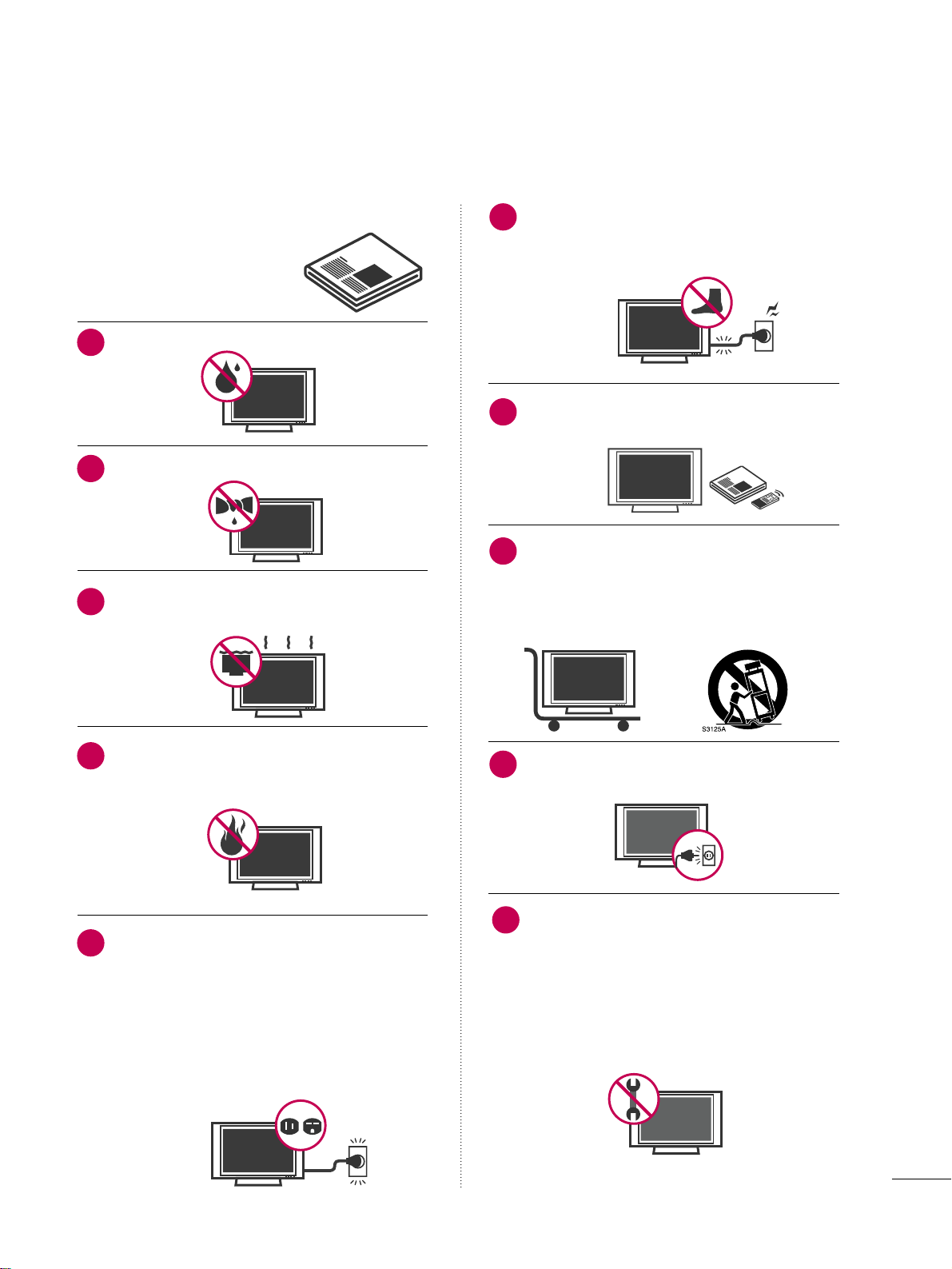
Do not make the TV with the power cord
plugged in. Do not use a damaged or loose
power cord. Be sure do grasp the plug when
unplugging the power cord. Do not pull on the
power cord to unplug the TV.
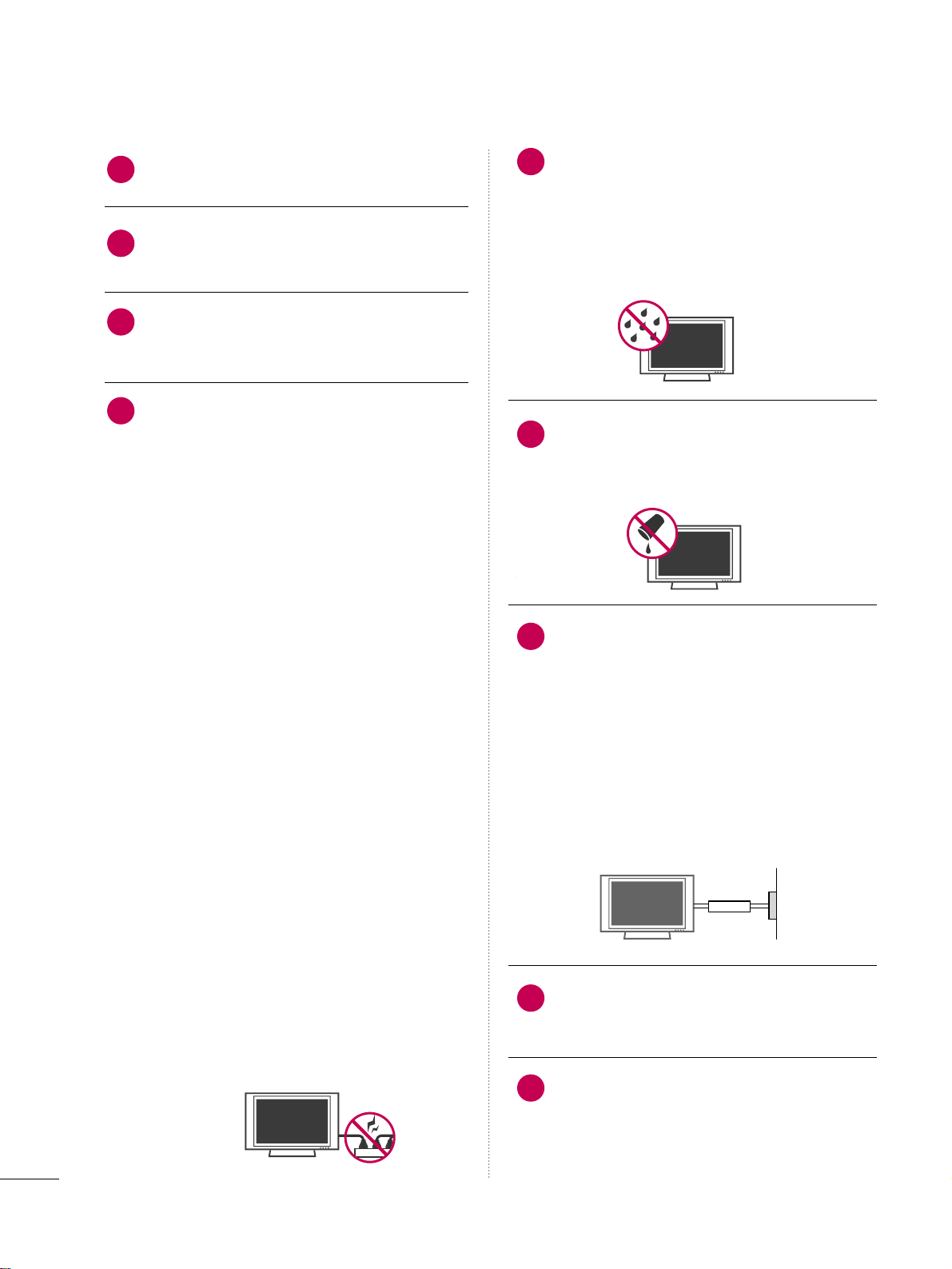
WARNING - To reduce the risk of fire or electrical
shock, do not expose this product to rain,
moisture or other liquids. Do not touch the TV
with wet hands. Do not install this product
near flammable objects such as gasoline or
candles or expose the TV to direct air
conditioning.
Do not expose to dripping or splashing and do
not place objects filled with liquids, such as
vases, cups, etc. on or over the apparatus e.g.
on shelves above the unit).
GGRROOUUNNDDIINNGG
Ensure that you connect the earth ground wire
to prevent possible electric shock i.e. a TV
with a three-prong grounded AC plug must be
connected to a three-prong grounded AC out-
let). If grounding methods are not possible,
have a qualified electrician install a separate
circuit breaker.
Do not try to ground the unit by connecting it
to telephone wires, lightening rods, or gas
pipes.
DDIISSCCOONNNNEECCTTIINNGG DDEEVVIICCEE FFRROOMM MMAAIINNSS
Mains plug is the disconnecting device. The
plug must remain readily operable.
As long as this unit is connected to the AC wall
outlet, it is not disconnected from the AC
power source even if you turn off this unit by
SWITCH.
12
11
14
13
16
17
18
19
Power
Supply
Short-circuit
Breaker
15

5
AANNTTEENNNNAASS
OOuuttddoooorr aanntteennnnaa ggrroouunnddiinngg
If an outdoor antenna is installed, follow the
precautions below. An outdoor antenna system
should not be located in the vicinity of over-
head power lines or other electric light or
power circuits, or where it can come in contact
with such power lines or circuits as death or
serious injury can occur.
Be sure the antenna system is grounded so as
to provide some protection against voltage
surges and built-up static charges.
Section 810 of the National Electrical Code
NEC) in the U.S.A. provides information with
respect to proper grounding of the mast and
supporting structure, grounding of the lead-in
wire to an antenna discharge unit, size of
grounding conductors, location of antenna dis-
charge unit, connection to grounding elec-
trodes and requirements for the grounding
electrode.
AAnntteennnnaa ggrroouunnddiinngg aaccccoorrddiinngg ttoo tthhee
NNaattiioonnaall EElleeccttrriiccaall CCooddee,, AANNSSII//NNFFPPAA 7700
CClleeaanniinngg
When cleaning, unplug the power cord and
scrub gently with a soft cloth to prevent
scratching. Do not spray water or other liquids
directly on the TV as electric shock may occur.
Do not clean with chemicals such as alcohol,
thinners or benzene.
MMoovviinngg
Make sure the product is turned off,
unplugged and all cables have been removed. It
may take 2 or more people to carry larger TVs.
Do not press against or put stress on the front
panel of the TV.
VVeennttiillaattiioonn
Install your TV where there is proper ventila-
tion. Do not install in a confined space such as
a bookcase. Do not cover the product with
cloth or other materials e.g.) plastic while
plugged in. Do not install in excessively dusty
places.
If you smell smoke or other odors coming from
the TV or hear strange sounds, unplug the power
cord contact an authorized service center.
Do not press strongly upon the panel with
hand or sharp object such as nail, pencil or
pen, or make a scratch on it.
Keep the product away from direct sunlight.
If the TV feels cold to the touch, there may be
a small “flicker” when it is turned on. This is
normal, there is nothing wrong with TV.
Some minute dot defects may be visible on the
screen, appearing as tiny red, green, or blue
spots. However, they have no adverse effect on
the monitor's performance.
Avoid touching the LCD screen or holding your
finger s) against it for long periods of time.
Doing so may produce some temporary dis-
tortion effects on the screen.
20 23
24
25
26
27
21
22
Antenna Lead in Wire
Antenna Discharge Unit
(NEC Section 810-20)
Grounding Conductor
(NEC Section 810-21)
Ground Clamps
Power Service Grounding
Electrode System (NEC
Art 250, Part H)
Ground Clamp
Electric Service
Equipment
NEC: National Electrical Code
ON DISPOSAL
(Only Hg lamp used LCD TV)
The fluorescent lamp used in this product contains
a small amount of mercury. Do not dispose of
this product with general household waste.
Disposal of this product must be carried out in
accordance to the regulations of your local authority.

PREPARATION
9
ACCESSORIES
PREPARATION
Ensure that the following accessories are included with your TV. If an accessory is missing, please contact the
dealer where you purchased the TV.
The accessories included may differ from the images below.
Owner’s Manual Power Cord
CD Manual
OOppttiioonn EExxttrraass
* Wipe spots on the exterior only with
the polishing cloth.
* Do not wipe roughly. Excessive pres-
sure may cause scratches or discol-
oration.
Polishing Cloth
Not included with all models
D-sub 15 pin Cable
When using the VGA D-sub 15 pin
cable) PC connection, the user
must use shielded signal interface
cables with ferrite cores to maintain
standards compliance.
OOnnllyy 4422//4477//5555LLHH9900
1.5V 1.5V
Remote Control, Batteries
FAV
MUTE
Q.MENU
MENU
AVMODE
RETURN
VOL CH
123
456
78
0
9
FLASHBK
P
A
G
E
INPUT
INFO
LIST
ENTER
POWER
TV
ENERGY SAVING
ON/OFF
MARK
Protection Cover
Screws for stand assembly
(Refer to P.14
Screw for stand fixing
(Refer to P.21
x 4
(For 42/47LH90
(For 42LH90
OOnnllyy 4422//4477SSLL9900
Bolts for stand assembly
(Refer to P.16
Cable Management Clip
(Refer to P.19
Cable Holder
(Refer to P.19
x 1
OOnnllyy 4422//4477//5555SSLL8800
Bolts for stand assembly
(Refer to P.15
Cable Management Clip
(Refer to P.18
Protection Cover
(Refer to P.15
x 8
(Except 55SL80
Cable Holder
(Refer to P.18
Simple Remote Control,
Batteries
1.5V 1.5V
CH
VOL
FLASHBACK
TV/INPUT
x 3 x 4
POWER
AV
MODE
ENERGYSAVING
P
A
G
E
CHVOL
FAV
MARK/
MUTE
ON/OFF
123
45
0
6
789
LIST
FLASHBACK
INPUT
MENURATIO
Q.MENU
RETURN
INFO
ENTER
TV
or

PREPARATION
10
FRONT PANEL INFORMATION
PREPARATION
■
Image shown may differ from your TV.
INPUT
MENU
ENTER
CH
VOL
CHANNEL ( ,
Buttons
VOLUME (+, -
Buttons
ENTER Button
MENU Button
INPUT Button
POWER Button
AC power control switch
SPEAKER
Power/Standby Indicator
Illuminates red in standby mode.
Illuminates white when the TV is switched on.
Can be adjusted using the PPoowweerr IInnddiiccaattoorrin the
OPTION menu. GGpp..8844)
Remote Control Sensor,
Intelligent Sensor
Adjusts picture according to the
surrounding conditions
42/47/55LH90
42/47/55SL80
Main power switch
(For 42/47/55SL80
OFF ON
Remote Control Sensor
INPUT
MENU
ENTER
CH
VOL
INPUT
Button
POWER
Button
MENU
Button
ENTER
Button
CHANNEL
(,
Buttons
VOLUME
(-, +
Buttons
Power/Standby Indicator
Illuminates red in standby mode.
Illuminates blue when the TV is switched on Can be adjusted
using the PPoowweerr IInnddiiccaattoorrin the OPTION menu. GGpp..8844).
Intelligent Sensor
Adjusts picture
according to the
surrounding con-
ditions
GGDo not step on the glass stand or subject it to any impact.It may break, causing possible
injury from fragments of glass, or the TV may fall.
GGDo not drag the TV. The floor or the product may be damaged.
NOTE
!

PREPARATION
11
■
Image shown may differ from your TV.
42/47SL90
Main power switch
(For 42/47SL90
OFF ON
Power/Standby Indicator
Illuminates red in standby mode.
Illuminates blue when the TV is switched on Can be
adjusted using the PPoowweerr IInnddiiccaattoorrin the OPTION
menu. GGpp..8844).
GGDo not step on the glass stand or subject it to any impact.It may break, causing possible
injury from fragments of glass, or the TV may fall.
GGDo not drag the TV. The floor or the product may be damaged.
NOTE
!
INPUT
MENU
ENTER
CH
VOL
CHANNEL ( ,
Buttons
VOLUME (+, -
Buttons
ENTER Button
MENU Button
INPUT Button
POWER Button
Sensor de Control Remoto
Sensor Inteligente
Ajusta la imagen
según las condi-
ciones del entorno.

PREPARATION
1
PREPARATION
BACK PANEL INFORMATION
■
Image shown may differ from your TV.
VIDEO
AUDIO
L R
RS-232C IN
(
CONTROL&SERVICE)
AUDIO IN
(RGB/DVI)
OPTICAL DIGITAL
AUDIO OUT
ANTENNA/
CABLE IN
RGB IN (PC)
AV IN 1
COMPONENT IN
2
3
1
2
1
MONO
()
AUDIOVIDEO
/DVI IN
( )
( )
LR
R
1
6 57
9
( )
( )
( )
AV IN 2
L/MONO
R
AUDIO
VIDEO
USB IN
IN 4
1
8
4
3
42/47/55LH90
VIDEO
AUDIO
L R
(
CONTROL&SERVICE)
RS-232C IN
AUDIO IN
(RGB/DVI)
DIGITAL
AUDIO OUT
OPTICAL
ANTENNA/
CABLE IN
RGB IN (PC)
COMPONENT IN
2
3
1
1
2
MONO
()
AUDIOVIDEO
/DVI IN
LR
R
AV IN 1
R
4 3 6 5
1
7
42/47/55SL80
( )
R
R
9
( )
R
USB IN
IN 4
R
( )
R
AV IN 2
L/MONO
R
AUDIO
VIDEO
6
8

PREPARATION
13
42/47SL90
AV (Audio/Video IN
Analog composite connection. Supports standard
definition video only 480i).
HDMI/DVI IN, HDMI IN
Digital Connection.
Supports HD video and Digital audio. Doesn’t
support 480i.
Accepts DVI video using an adapter or HDMI to
DVI cable not included).
RGB IN (PC
Analog PC Connection. Uses a D-sub 15 pin cable
VGA cable).
AUDIO IN (RGB/DVI
1/8" 0.32 cm) headphone jack for analog PC
audio input.
OPTICAL DIGITAL AUDIO OUT
Digital optical audio output for use with amps and
home theater systems.
Note: In standby mode, this port doesn’t work.
ANTENNA/CABLE IN
Connect over-the air signals to this jack.
Connect cable signals to this jack.
RS-232C IN (CONTROL & SERVICE PORT
Used by third party devices.
This port is used for Service or Hotel mode.
COMPONENT IN
Analog Connection.
Supports HD.
Uses a red, green, and blue cable for video & red
and white for audio.
USB IN
Used for viewing photos/movies and listening to
MP3s.
Power Cord Socket
For operation with AC power.
Caution: Never attempt to operate the TV on DC
power.
1
3
4
8
9
7
6
5
VIDEO
AUDIO
L R
(
CONTROL&SERVICE)
RS-232C IN
AUDIO IN
(RGB/DVI)
DIGITAL
AUDIO OUT
OPTICAL
ANTENNA/
CABLE IN
RGB IN (PC)
COMPONENT IN
2
3
1
1
2
MONO
()
AUDIOVIDEO
/DVI IN
LR
R
AV IN
( )
R
USB IN
IN 4
8
4 3 6 5
1
7
ANTENNA
IN
L/MONO
R
AUDIO
VIDEO
CABLE IN
9

PREPARATION
3
ANTENNA OR CABLE CONNECTION
■
To prevent damage do not connect to the power outlet until all connections are made between the devices.
■
Image shown may differ from your TV.
1. Antenna (Analog or Digital)
Wall Antenna Socket or Outdoor Antenna without a Cable Box
Connections.
For optimum picture quality, adjust antenna direction if needed.
. Cable
Wall
Antenna
Socket
Outdoor
Antenna
(VHF, UHF)
Cable TV
Wall Jack
Multi-family Dwellings/Apartments
(Connect to wall antenna socket)
RF Coaxial Wire (75 ohm)
Single-family Dwellings /Houses
(Connect to wall jack for outdoor antenna)
Be careful not to bend the copper wire
when connecting the antenna.
Copper Wire
■To improve the picture quality in a poor signal area, please purchase a signal amplifier and install properly.
■If the antenna needs to be split for two TV’s, install a 2-Way Signal Splitter.
■If the antenna is not installed properly, contact your dealer for assistance.
( )
R
( )
R

EXTERNAL EQUIPMENT SETUP
4
EXTERNAL EQUIPMENT SETUP
HD RECEIVER SETUP
This TV can receive digital over-the-air/digital cable signals without an external digital set-top box. However, if
you do receive digital signals from a digital set-top box or other digital external device.
Component Connection
1. How to connect
Connect the video outputs Y, PB, PR)of the digital set-
top box to the CCOOMMPPOONNEENNTT IINN VVIIDDEEOO 11 or 22
jacks on the TV. Match the jack colors Y = green, PB=
blue, and PR= red).
Connect the audio output of the digital set-top box to
the CCOOMMPPOONNEENNTT IINN AAUUDDIIOO 11or 22 jacks on the TV.
2
1
. How to use
■Turn on the digital set-top box.
Refer to the owner’s manual for the digital set-top box operation.)
■Select the CCoommppoonneenntt11or 22 input source on the TV
using the IINNPPUUTTbutton on the remote control.
■To prevent the equipment damage, never plug in any power cords until you have finished connecting all equipment.
■
This part of EXTERNAL EQUIPMENT SETUP mainly use picture for 4422//4477//5555LLHH9900.
Y, CB/PB, CR/PR
Supported Resolutions
Horizontal Vertical
Frequency KHz)Frequency Hz)
15.73 59.94
15.73 60.00
31.47 59.94
31.50 60.00
44.96 59.94
45.00 60.00
33.72 59.94
33.75 60.00
26.97 23.976
27.00 24.00
33.71 29.97
33.75 30.00
67.432 59.94
67.50 60.00
Resolution
720x480i
720x480p
1280x720p
1920x1080i
1920x1080p
Signal
480i
480p
720p
1080 i
1080 p
Component
Yes
Yes
Yes
Yes
Yes
HDMI
No
Yes
Yes
Yes
Yes
AV IN 1
2
3
1
MONO
()
AUDIOVIDEO L R
/DVI IN
( )
VIDEO
AUDIO
L R
COMPONENT IN
2
1
Y L RPBPR
( )
1

EXTERNAL EQUIPMENT SETUP
5
HDMI Connection
Connect the digital set-top box to HHDDMMII//DDVVII IINN 11,
22, 33, or 44 jack on the TV.
No separate audio connection is necessary.
HDMI supports both audio and video.
1. How to connect
. How to use
■Turn on the digital set-top box.
Refer to the owner’s manual for the digital set-top box.)
■Select the HHDDMMII11, HHDDMMII22, HHDDMMII33, or HHDDMMII44 input
source on the TV using the IINNPPUUTTbutton on the remote
control.
2
1
HDMI-DTV
Horizontal Vertical
Frequency KHz)Frequency Hz)
31.47 59.94
31.50 60.00
44.96 59.94
45.00 60.00
33.72 59.94
33.75 60.00
26.97 23.976
27.00 24.00
33.71 29.97
33.75 30.00
67.432 59.94
67.50 60.00
Resolution
720x480p
1280x720p
1920x1080i
1920x1080p
( )
EO
AUDIO
L R
RS-232C IN
(
CONTROL&SERVICE)
AUDIO IN
(RGB/DVI)
O
A
C
RGB IN (PC)
AV IN 1
OMPONENT IN
1
MONO
()
AUDIOVIDEO L R
2
3
1
/DVI IN
HDMI OUTPUT
( )
1
GGCheck HDMI cable over version 1.3.
If the HDMI cables don’t support HDMI version 1.3, it can
cause flickers or no screen display. In this case use the lat-
est cables that support HDMI version 1.3.
GGHDMI mode supports PCM, Dolby Digital audio format.
NOTE
!

EXTERNAL EQUIPMENT SETUP
6
EXTERNAL EQUIPMENT SETUP
DVI to HDMI Connection
( )
( )
AUDIO
L R
RS-232C IN
(
CONTROL&SERVICE)
OPTICAL DIG
AUDIO OU
ANTENNA
CABLE IN
RGB IN (PC)
AV IN 1
ENT IN
1
MONO
()
AUDIOLR
2
3
1
/DVI IN
AUDIO IN
(RGB/DVI)
L R
DVI OUTPUT AUDIO
1
GGA DVI to HDMI cable or adapter is required for this con-
nection. DVI doesn't support audio, so a separate audio
connection is necessary.
NOTE
!
Connect the DVI output of the digital set-top box to
the HHDDMMII//DDVVII IINN 11, 22, or 33jack on the TV.
Connect the digital set-top box audio output to the
AAUUDDIIOO IINN RRGGBB//DDVVII))jack on the TV.
1. How to connect
. How to use
■Turn on the digital set-top box.
Refer to the owner’s manual for the digital set-top box.)
■Select the HHDDMMII11, HHDDMMII22, or HHDDMMII33 input source on the
TV using the IINNPPUUTTbutton on the remote control.
2
1

EXTERNAL EQUIPMENT SETUP
8
EXTERNAL EQUIPMENT SETUP
Composite (RCA Connection
VIDEO
AUDIO
L R
COMPONENT IN
2
3
1
2
1
/DVI IN
( )
( )
AV IN 1
MONO
()
AUDIOVIDEO LR
L R
VIDEO
AUDIO
HDMI Connection
( )
O
AUDIO
L R
RS-232C IN
(
CONTROL&SERVICE)
AUDIO IN
(RGB/DVI)
OPT
A
AN
C
RGB IN (PC)
AV IN 1
MPONENT IN
1
MONO
()
AUDIOVIDEO L R
2
3
1
/DVI IN
HDMI OUTPUT
( )
1
Connect the AAUUDDIIOO/VVIIDDEEOOjacks between TV and
DVD. Match the jack colors Video = yellow, Audio Left
= white, and Audio Right = red)
1. How to connect
. How to use
■Turn on the DVD player, insert a DVD.
■Select the AAVV11or AAVV22input source on the TV using the
IINNPPUUTTbutton on the remote control.
■Refer to the DVD player's manual for operating instructions.
1
Connect the HDMI output of the DVD to the
HHDDMMII//DDVVII IINN 11, 22, 33 or 44jack on the TV.
No separate audio connection is necessary.
HDMI supports both audio and video.
1. How to connect
. How to use
■Select the HHDDMMII11, HHDDMMII22, HHDDMMII33, or HHDDMMII44input
source on the TV using the IINNPPUUTTbutton on the remote
control.
■Refer to the DVD player's manual for operating instructions.
2
1
GGCheck HDMI cable over version 1.3.
If the HDMI cables don’t support HDMI version 1.3, it can
cause flickers or no screen display. In this case use the lat-
est cables that support HDMI version 1.3.
NOTE
!
1

EXTERNAL EQUIPMENT SETUP
30
PC SETUP
EXTERNAL EQUIPMENT SETUP
This TV provides Plug and Play capability, meaning that the PC adjusts automatically to the TV's settings.
VGA (D-Sub 15 pin Connection
RS-232C IN
(
CONTROL&SERVICE)
OPTICAL DIGITAL
AUDIO OUT
ANTENNA/
CABLE IN
2
3
1
( )
R
/DVI IN
AUDIO IN
(RGB/DVI)
RGB IN (PC)
RGB OUTPUT
AUDIO
( )
1
Connect the VGA output of the PC to the RRGGBB IINN
PPCC))jack on the TV.
Connect the PC audio output to the AAUUDDIIOO IINN
RRGGBB//DDVVII))jack on the TV.
1. How to connect
. How to use
■Turn on the PC and the TV.
■Select the RRGGBB--PPCCinput source on the TV using the
IINNPPUUTTbutton on the remote control.
2
1
DVI to HDMI Connection
( )
O
AUDIO
L R
RS-232C IN
(
CONTROL&SERVICE)
OP
A
A
C
RGB IN (PC)
AV IN 1
MPONENT IN
MONO
()
AUDIOVIDEO L R
AUDIO IN
(RGB/DVI)
2
3
1
/DVI IN
AUDIO
DVI OUTPUT
1
Connect the DVI output of the PC to the HHDDMMII//DDVVII
IINN 11, 22, or 33jack on the TV.
Connect the PC audio output to the AAUUDDIIOO IINN
RRGGBB//DDVVII))jack on the TV.
1. How to connect
. How to use
■Turn on the PC and the TV.
■Select the HHDDMMII11, HHDDMMII22, or HHDDMMII33input source on
the TV using the IINNPPUUTTbutton on the remote control.
2
1
GGCheck HDMI cable over version 1.3.
If the HDMI cables don’t support HDMI version 1.3, it can
cause flickers or no screen display. In this case use the lat-
est cables that support HDMI version 1.3.
NOTE
!

EXTERNAL EQUIPMENT SETUP
31
NOTES
!
Supported Display Specifications (RGB-PC, HDMI-PC)
Resolution
720x400
640x350
Horizontal Vertical
Frequency KHz)Frequency Hz)
31.468 70.09
31.469 70.08
31.469 59.94
37.879 60.31
48.363 60.00
47.776 59.87
47.712 60.015
63.981 60.02
75.00 60.00
66.587 59.934
67.50 60.00
640x480
800x600
1024x768
1280x768
1280x1024
1360x768
1600x1200
1920x1080
RGB-PC
1920x1080
HDMI-PC
GGTo get the best picture quality, adjust the PC graph-
ics card to 1920x1080.
GGDepending on the graphics card, DOS mode may
not work if an HDMI to DVI Cable is in use.
GGIn PC mode, there may be noise associated with
the resolution, vertical pattern, contrast or bright-
ness. If noise is present, change the PC output to
another resolution, change the refresh rate to
another rate or adjust the brightness and contrast
on the PICTURE menu until the picture is clear.
GGAvoid keeping a fixed image on the screen for a
long period of time. The fixed image may become
permanently imprinted on the screen.
GGDepending on the graphics card, some resolution
settings may not allow the image to be positioned
on the screen properly.
GGIf the screen is truncated using HDMI-PC
1920x1080, try changing the aspect ratio to JJuusstt
ssccaann.
GGWhen selecting HDMI-PC, set the “Input Label -
PC” in the OPTION menu.

EXTERNAL EQUIPMENT SETUP
3
EXTERNAL EQUIPMENT SETUP
Screen Setup for PC mode
Selecting Resolution
You can choose the resolution in RGB-PC mode.
The PPoossiittiioonn, PPhhaassee, and SSiizzeecan also be adjusted.
Select PPIICCTTUURREE.
Select SSccrreeeenn RRGGBB--PPCC)).
Select RReessoolluuttiioonn.
Select the desired resolution.
1024 x 768
1280 x 768
1360 x 768
Auto Config.
Resolution
Position
Size
Phase
Reset
SCREEN
Move
Prev.
1
MENU
3
4
2
ENTER
ENTER
ENTER
5
ENTER
Enter
Move
PICTURE
E
RG
• Brightness 50
• Sharpness 50
• Color 50
• Tint 0
• Advanced Control
• Picture Reset
Screen (RGB-PC)
LED Local Dimming :On

EXTERNAL EQUIPMENT SETUP
33
Auto Configure
Automatically adjusts picture position and minimizes image instability. After adjustment, if the image is still
not correct, try using the manual settings or a different resolution or refresh rate on the PC.
Select SSccrreeeenn RRGGBB--PPCC)).
Select AAuuttoo CCoonnffiigg...
Auto Config.
Resolution
Position
Size
Phase
Reset
SCREEN
Move
Prev.
To Set
3
2
ENTER
ENTER
Select YYeess.
4
ENTER
Start Auto Configuration.
5
ENTER
Select PPIICCTTUURREE.
1
MENU
■If the position of the image is still not
correct, try Auto adjustment again.
■If picture needs to be adjusted again
after Auto adjustment in RGB-PC, you
can adjust the PPoossiittiioonn, SSiizzee or
PPhhaassee.
Yes No
Enter
Move
PICTURE
E
RG
• Brightness 50
• Sharpness 50
• Color 50
• Tint 0
• Advanced Control
• Picture Reset
Screen (RGB-PC)
LED Local Dimming :On
This manual suits for next models
15
Table of contents
Other LG TV manuals