CONTENTS
EOIN
EINES
5
casas
a
ccaeten
sexes
soaah
aaa
annus
ccadectassd
eas
c
aataet
aahnrdtnadeneoussccasy
ates
Sista
aan
2
DAISY
PreCaG
ti
ONS
555s
wistesiels
Sas
Geascareasisiee
esters
tesstack
pec
anaes
sata
eeaeetaee
3
SELVICHIIG
PRECAUTIONS
55
sccsscssscivsscctins
cetera
cetaneinussipanvrndensintvisteeleis
arsed
nauilade
aes
4
SPO
CUL
IC
AEE
OINS
stat
tnasdevcusvinsirascalucesurts
cecbeadnetodaeantanetin
aan
ndieaneetntecton
paid
ina
veoks
6
Control
DESSripet
tis
ceicesssssscasicsedssschassassvagdsecccstuvavesdcdesaviceQopnaseesdante
bevecseeevesdiatacentecavissiesecdcies!
7
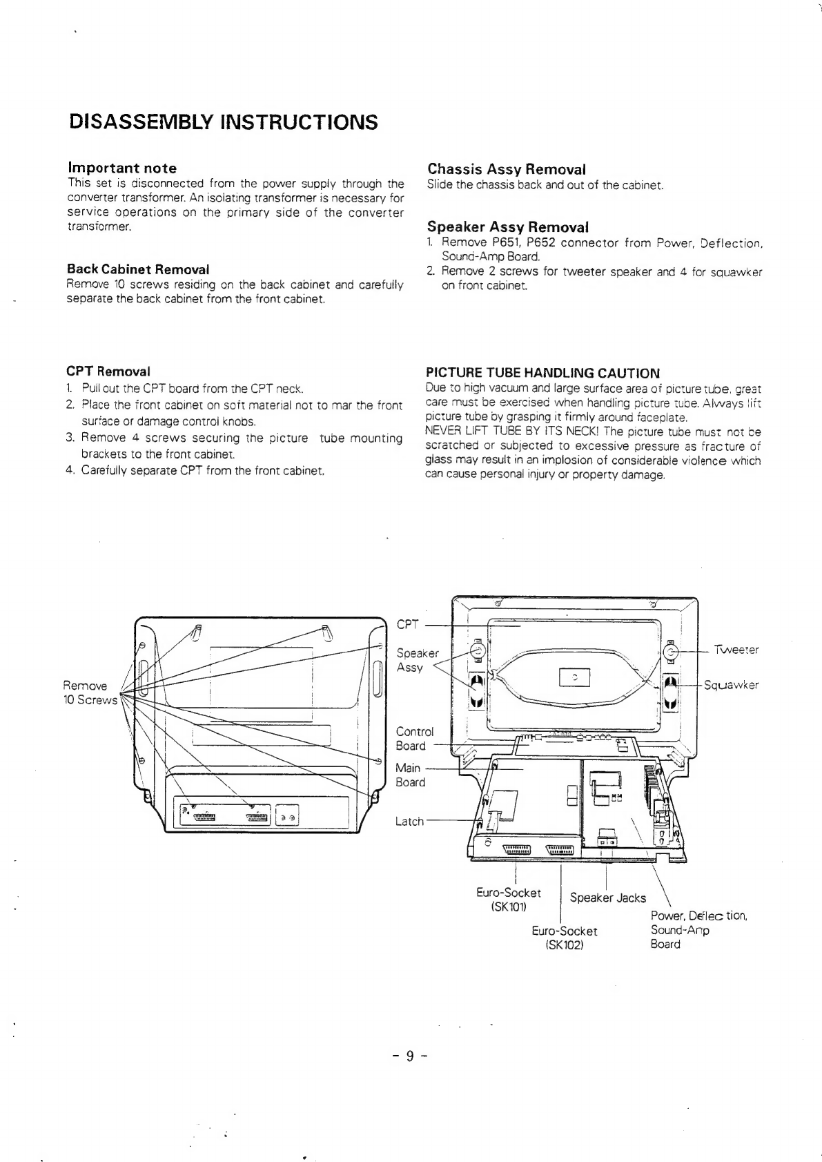
Disassembly
INStructiOns
.....c..cscssssscssssscssssssssssssessesssssssssecssssessscssucssssssesstssssscssssssssssssessensensece
9
ERI
O
USE
VW
sess
ie
ak
Gia
ca
ee
aa
aca
ead
ct
ta
Santa
a
ean
ee.
10
Exploded
View
Parts
List
.........ssssssssssssssssssssssesssssserssessssesssessrsasecesssssessoscessssesssssssssstasosessneeses
11
Replacement
Parts
List
...........ssccssssscsssssscssssssssesssesensesssssusessesssessnersssvscesessesssanserstarsescessesuesene
12
Scie
rata
tice
Deicke
ean
ese
siesta
cucu
ss
eases
cis
oates
esas
ovnpvaaendceanclvaseoviusgueibslen
Retetaasodkthecsieoek
BMG
INGO
Ease
cssi
cicadas
ces
deeacte
tessa
cade
aasaers
ET
coc
crea
aeactec
pleat
eetatae
lends
oh
&