LG M2362D User manual

www.lg.com
OWNER’S MANUAL
MONITOR TV
MONITOR TV MODELS
Please read this manual carefully before operating
your set and retain it for future reference.
ENGLISH
M2362D

1
PREPARATION
FRONT PANEL CONTROLS
■
This is a simp ified representation of the front pane . The image shown may be somewhat different from your set.
INPUT
Button
INPUT
MENU
PR
VOL
OK
MENU
Button
OK
Button
VOLUME
Buttons
PROGRAMME
Buttons
Power
Button
Headphone
Jack
IR receiver
(Remote contro er
receiver)
LLiigghhtt SSeennssoorr
This is ens for ight sensor
se ect outside uminance,
when setting AUTO
BRIGHT ON.
PPoowweerr IInnddiiccaattoorr
i uminates b ue when the
set is switched on.
Note:You can adjust
Power indicator in the
OPTION menu.

22
PREPARATION
BACK PANEL INFORMATION
PPoowweerr CCoorrdd SSoocckkeett
This set operates on AC power. The vo tage is indicated
on the Specifications page. Never attempt to operate
the set on DC power.
HHDDMMII IInnppuutt ((NNoott SSuuppppoorrtt PPCC))
Connect a HDMI signa to HDMI IN.
Or DVI (VIDEO) signa to HDMI IN with DVI to HDMI
cab e.
RRGGBB//DDVVII AAuuddiioo IInnppuutt
Connect the audio from a PC.
OOppttiiccaa DDiiggiittaa AAuuddiioo OOuutt
Connect digita audio from various types of eguipment
RRGGBB IINNPPUUTT ((PPCC))
Connect the output from a PC.
UUSSBB IINN
DDVVII--DD IInnppuutt
Connect the output from a PC.
RRSS--223322CC IINN ((CCOONNTTRROOLL && SSEERRVVIICCEE)) PPOORRTT
Connect to the RS-232C port on a PC.
CCoommppoonneenntt IInnppuutt
Connect a component video/audio device to these
jacks.
AAuuddiioo//VViiddeeoo IInnppuutt
Connect audio/video output from an externa device to
these jacks.
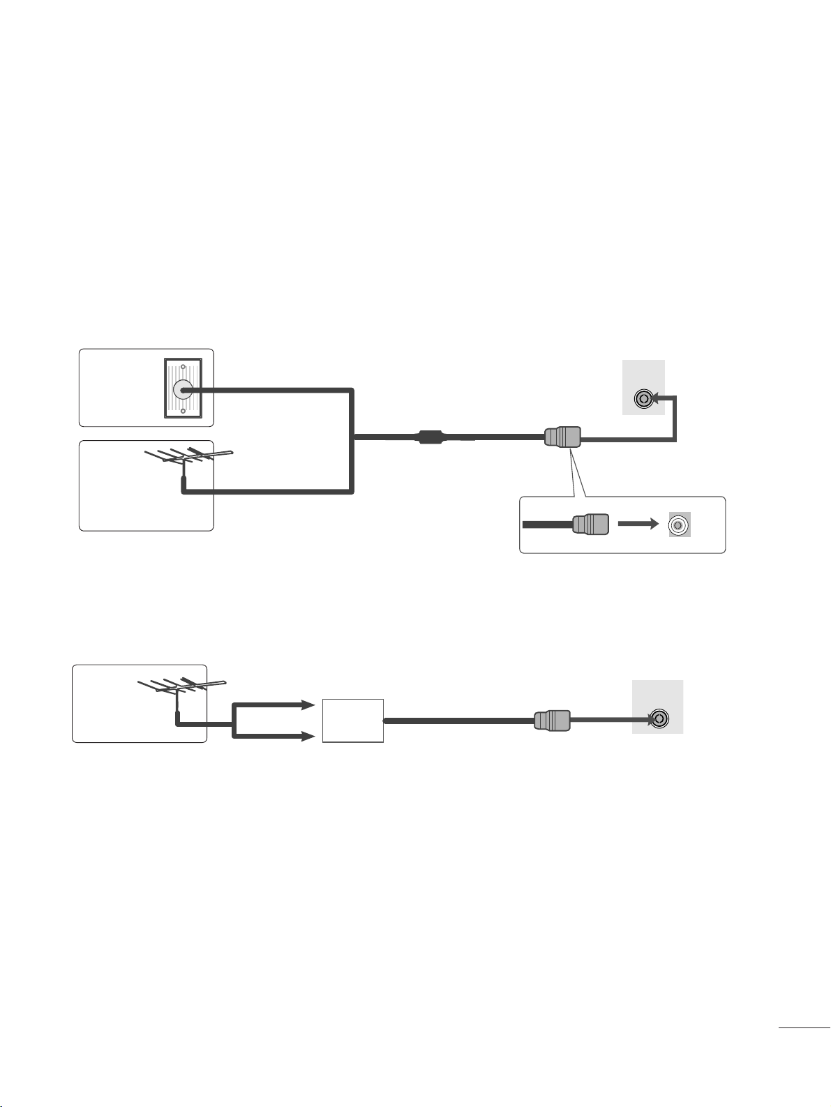
AAnntteennnnaa IInnppuutt
Connect over-the-air signa s to this jack.
1
2
3
4
5
6
7
8
9
10
11
■
This is a simp ified representation of the back pane . The image shown may be somewhat different from your set.
AC IN
AUDIO IN
(RGB/DVI) OPTICAL
DIGITAL
AUDIO OUT
VIDEO
COMPONENT
IN
AV IN
VIDEO -AUDIO-
(MONO)
AUDIO
Y
P
B
P
R
L
R
RS-232C IN
(CONTROL & SERVICE)
USB IN
RGB IN (PC)
DVI-D IN (PC)
HDMI IN 1
AC IN
ANTENNA/
CABLE IN
LR
2
8910
1
2
76 11
53 4

33
PREPARATION
STAND INSTALLATION
■
The image shown may be somewhat different from your set.
2
3
Carefully place the product screen side down on a
cushioned surface that will protect product and
screen from damage.
Insert the SSttaanndd BBaasseeinto the product
Turn the SSttaanndd BBaassee LLoocckkthrough 90°to fix the stand base to the stand body.
SSttaanndd BBaassee LLoocckk
<<LLoocckkeedd>>
4 5
O
P
E
N
O
P
E
N
O
P
E
N
O
P
E
N
SSttaanndd BBaassee

44
PREPARATION
DETACHING STAND
■
The image shown may be somewhat different from your set.
2
3
4
Place the set screen side down on a cushion or
soft cloth.
Detach the monitor to the SSttaanndd BBaasseeby
turning the screw to the left.
Turn the SSttaanndd BBaassee LLoocckk through 90°to separate the Stand Base from the Stand Body.
Pushing LLaattcchhinside, Take the stand base from stand body.
O
P
E
N
O
P
E
N
O
P
E
N
O
P
E
N
O
P
E
N
O
P
E
N
LLaattcchh
SSttaanndd BBaassee

55
PREPARATION
DETACHING STAND BODY
1. Remove the screw 2 point.
2. Pu the stand body.
■
The image shown may be somewhat different from your set.
■
Remove the Stand Body in the same way as the fo owing when using it as a Wa Hook.

66
PREPARATION
DESKTOP PEDESTAL INSTALLATION
For proper ventilation, allow a clearance of 10 c on each side and fro the wall.
10 c
10 c
10 c
10 c
WALL MOUNT: HORIZONTAL INSTALLATION
For proper ventilation, allow a clearance of 10 c on each side and fro the wall. Detailed installation
instructions are available fro your dealer, see the optional Tilt Wall Mounting Bracket Installation and
Setup Guide.
10 c
10 c
10 c 10 c
10 c

77
PREPARATION
POSITIONING YOUR DISPLAY
■
The image shown may be somewhat different from your set.
Adjust the position of the pane in various ways for maximum comfort.
•• TTiitt rraannggee
LOCATION
Position your set so that no bright ight or sun ight fa s direct y onto the screen. Care shou d be taken not to expose
the set to any unnecessary vibration, moisture, dust or heat. A so, ensure that the set is p aced in a position to a ow a
free f ow of air. Do not cover the venti ation openings on the back cover.
If you intend to mount the set to a wa , attach Wa mounting interface (optiona parts) to the back of the set.
When you insta the set using the wa mounting interface (optiona parts), attach it carefu y so it wi not drop.
- Be sure to use screws and a wa mount that meet VESA standards.
- Using screws onger than those recommended might damage the product.
- Using screws that do not meet VESA standards might either damage the product or resu t in it coming away from the
wa . We wi not be he d responsib e for any damage resu ting from fai ure to fo ow these instructions.
< Screw Mounting Interface Dimension >
100mm x 100mm ho e spacing
-5
°
15
°
WWaarrnniinngg::
When adjusting the ang e of the screen,do not put your
finger(s)in between the head of the monitor and the stand
body.You can hurt your finger(s).

88
PREPARATION
KENSINGTON SECURITY SYSTEM
- The product is equipped with a Kensington Security System connector on the back pane . Connect the
Kensington Security System cab e as shown be ow.
- For detai ed insta ation and use of the Kensington Security System, refer to the user’s guide provided with the
Kensington Security System.
For further information, contact hhttttpp::////wwwwww..kkeennssiinnggttoonn..ccoomm, the internet homepage of the Kensington
company. Kensington se s security systems for expensive e ectronic equipment such as notebook PCs and
LCD projectors.
NOTE
- The Kensington Security System is an optiona accessory.
NOTES
a. If the product fee s co d to the touch, there may be a sma “f icker” when it is turned on.
This is norma , there is nothing wrong with product.
b. Some minute dot defects may be visib e on the screen, appearing as tiny red, green, or b ue spots. However,
they have no adverse effect on the monitor's performance.
c. Avoid touching the LCD screen or ho ding your finger(s) against it for ong periods of time.
Doing so may produce some temporary distortion effects on the screen.

99
AV 1 AV 2
ANTENNA/
CABLE IN
AV 1 AV 2
ANTENNA/
CABLE IN
EXTERNAL EQUIPMENT SETUP
■For optimum picture qua ity, adjust antenna direction.
■An antenna cab e and converter are not supp ied.
■To prevent equipment damage, never p ug in any power cords unti you have finished connecting a equipment.
Mu ti-fami y Dwe ings/Apartments
(Connect to wa antenna socket)
Sing e-fami y Dwe ings /Houses
(Connect to wa jack for outdoor antenna)
Outdoor
Antenna
(VHF, UHF)
Wa
Antenna
Socket
RF Coaxia Wire (75 ohm)
ANTENNA CONNECTION
Antenna
UHF
Signa
Amp ifier
VHF
■In poor signa areas, to get better picture qua ity, insta a signa amp ifier to the antenna as shown above.
■If signa needs to be sp it for two TVs, use an antenna signa sp itter for connection.

1100
EXTERNAL EQUIPMENT SETUP
Connect the SET-TOP outputs to the CCOOMMPPOONNEENNTT IINN
VVIIDDEEOOsockets (Y PBPR) on the set.
Connect the audio cab e from the SET-TOP to CCOOMMPPOO--
NNEENNTT IINNAAUUDDIIOOsockets of the set.
Press the IINNPPUUTTbutton to se ect CCoommppoonneenntt..
2
3
1
HD RECEIVER SETUP
■To prevent the equipment damage, never p ug in any power cords unti you have finished connecting a equipment.
■
The image shown may be somewhat different from your set.
When connecting with a component cab e
Signa
480i/576i
480p/576p
720p/1080i
108 0 p
Component
Yes
Yes
Yes
Yes
HDMI
No
Yes
Yes
Yes
VIDEO
COMPONENT
IN
AUDIO
Y
P
B
P
R
L
R
1
2

1111
EXTERNAL EQUIPMENT SETUP
When connecting with a HDMI
Connect the HDMI output of the digita set-top box to the
HHDDMMII IINNjack on the set.
1
Connect the digita set-top box to HHDDMMII IINN jack on
the set.
Connect the audio output of the digita set-top box to
the AAUUDDIIOO IINN ((RRGGBB//DDVVII)) jack on the set.
Turn on the digita set-top box. (Refer to the owner’s
manua for the digita set-top box.)
2
3
1
When connecting with a HDMI to DVI cab e
NOTE
!
G
HDMI Input does not support PC mode. If it is connected PC, the screen may not be disp ayed proper y.
or
HDMI IN 1
1
HDMI IN 2
HDMI IN 2
DVI OUTPUT
AUDIO
RL
AUDIO IN
(RGB/DVI)
HDMI IN 1
12
or

1122
EXTERNAL EQUIPMENT SETUP
DVD SETUP
When connecting with a component cab e
Component Input ports
To get better picture qua ity, connect a DVD p ayer to the component input ports as shown be ow.
Component ports on the set
YP
BPR
Video output ports
on DVD p ayer
Y
Y
Y
Y
PB
B-Y
Cb
Pb
PR
R-Y
Cr
Pr
Connect the video output sockets (Y PBPR) of the DVD to
the CCOOMMPPOONNEENNTT IINN VVIIDDEEOO sockets (Y PBPR) of the set.
Connect the audio cab e from the DVD to CCOOMMPPOONNEENNTT
IINN AAUUDDIIOO sockets of the set.
Press the IINNPPUUTTbutton to se ect CCoommppoonneenntt.
Press the PPLLAAYYbutton on the DVD.
The DVD p ayback picture appears on the screen.
2
3
4
1
VIDEO
COMPONENT
IN
AUDIO
Y
P
B
P
R
L
R
1
2

1133
EXTERNAL EQUIPMENT SETUP
When connecting HDMI cab e
Connect the HDMI output of the DVD to the
HHDDMMII IINN jack on the set.
1
GSet can receive the video and audio signa simu taneous y by using a HDMI cab e.
G If the DVD p ayer does not support Auto HDMI, you need to set the DVD output reso ution appropriate y.
NOTE
!
or
HDMI IN 1
1
HDMI IN 2

1144
EXTERNAL EQUIPMENT SETUP
VCR SETUP
■To avoid picture noise (interference), eave an adequate distance between the VCR and set.
■Typica y a sti picture is shown on the VCR. If a user uses 4:3 picture format for a ong time, an afterimage
may remain on the sides of the screen.
OUTPUT
SWITCH
ANT IN
R
S-VIDEO VIDEO
ANT OUT L
AV 1 AV 2
ANTENNA/
CABLE IN
Wa Jack
Antenna
1
2
When connecting with an antenna
Connect the RF out socket of the VCR to the aeria socket of the set.
Connect the aeria cab e to the RF aeria in socket of the VCR.
Store the VCR channe on a desired programme number using the ‘Manua
programme tuning’ section.
Se ect the programme number where the VCR channe is stored.
Press the PPLLAAYY button on the VCR.
1
2
3
4
5

1155
EXTERNAL EQUIPMENT SETUP
WWhheenn ccoonnnneeccttiinngg wwiitthh aa RRCCAA ccaabbee
Connect the audio/video out sockets of the VCR to
AUDIO/VIDEO in sockets of the set.
Press the INPUT button to se ect AV.
Press the PLAY button on the VCR.
The VCR p ayback picture appears on the screen.
2
3
1
NOTE
!
GIf you have a mono VCR, connect the audio cab e from the VCR to the AUDIO L/MONO jack of the set.
VIDEO ANT IN
ANT OUT
S-VIDEO LR
AV 1 AV 2
VIDEO AUDIO
(MONO)
LR
AV IN
1
Connect the USB device to the UUSSBB IINN jacks on the
side of set.
After connecting the UUSSBB IINN jacks, you use the UUSSBB
function. (Gpp..8800)
2
1
USB SETUP
AV 1 AV 2
USB IN
Connect one end of an optica cab e to the TV Digita
Audio (Optica )Output port.
Connect the other end of the optica cab e to the digi-
ta audio (Optica )input on the audio equipment.
Set the ““TTVV SSppeeaakkeerr ooppttiioonn -- OOffff ””in the AUDIO
menu.(Gpp..6633). Refer to the externa audio equipment
instruction manua for operation.
Sending the TV’s audio signa to externa audio equipment via the Digita Audio Output (Optica ) port.
If you want to enjoy digita broadcasting through 5.1-channe speakers, connect the OPTICAL DIGITAL AUDIO
OUT termina on the back of TV to a DVD Home Theater (or amp).
2
1
DIGITAL AUDIO OUT SETUP
GDo not ook into the optica output port. Looking at the
aser beam may damage your vision.
CAUTION

1166
EXTERNAL EQUIPMENT SETUP
PC SETUP
This product provides P ug and P ay capabi ity, meaning that the PC adjusts automatica y to the set's settings.
When connecting with a D-sub 15 pin cab e
4
Connect the signa cab e from the monitor output socket of
the PERSONAL COMPUTER to the PC input socket of the set.
Connect the audio cab e from the PC to the AAUUDDIIOO IINN
((RRGGBB//DDVVII))sockets of the set.
Press the INPUT button to se ect RRGGBB.
Switch on the PC, and the PC screen appears on the set.
The set can be operated as a PC monitor.
2
3
1
RGB OUTPUT AUDIO
AUDIO IN
(RGB/DVI)
RGB IN (PC)
12
NOTE
!
GYou must use shie ded signa interface cab es (D sub 15 pin cab e, DVI cab e) with ferrite cores to maintain
standard comp iance for the product.
GConnect the signa input cabe and tighten the screws by turning them c ockwise.

1177
EXTERNAL EQUIPMENT SETUP
When connecting with a DVI cab e
Connect the DVI output of the PC to the DDVVII--DD IINN
jack on the set.
Connect the audio cab e from the PC to the AAUUDDIIOO
IINN ((RRGGBB//DDVVII))sockets of the set.
2
1
NOTE
!
G
If the set is co d, there may be a sma “f icker” when the
set is switched on. This is norma , there is nothing
wrong with the set.
G
If possib e, use the 1920x1080 @ 60 Hz video mode
to obtain the best image qua ity for your LCD monitor.
If used with other reso utions, some sca ed or
processed pictures may appear on the screen. The set
has been preadjusted to the mode 1920x1080 @ 60
Hz.
G
Some dot defects may appear on the screen, ike Red,
Green or B ue spots. However, this wi have no impact
or effect on the monitor performance.
G
Do not press the LCD screen with your finger for a ong
time as this may produce some temporary distortion
effects on the screen.
G
Avoid keeping a fixed image on the set’s screen for pro-
onged periods of time. The fixed image may become
permanent y imprinted on the screen; use a screen
saver when possib e.
AUDIO
DVI OUTPUT
AUDIO IN
(RGB/DVI)
DVI-D IN (PC)
12
GConnect the signa input cabe and tighten the screws by turning them
c ockwise.

1188
EXTERNAL EQUIPMENT SETUP
Tie cab es together with a cab e tie as shown in the
i ustration.
BACK COVER FOR WIRE ARRANGEMENT
Cab e tie
R
R

1199
EXTERNAL EQUIPMENT SETUP
RGB/DVI[PC]
HDMI[DTV] (Not Support PC)
60
60
50
50
60
60
60
60
50
24
30
50
60
60
31 . 469
31 . 5
31 . 25
37.5
44.96
45
33.72
33.75
28.125
27
33.75
56.25
67.43
67.5
Reso ution
720x480/60p
720x576/50p
1280x720/60p
1280x720/50p
Horizonta
Frequency(kHz) Vertica
Frequency(Hz)
1920x1080/60i
1920x1080/50i
1920x1080/24p
1920x1080/30p
1920x1080/50p
Reso ution
640x480
800x600
720x400
1024x768
Horizonta
Frequency(kHz) Vertica
Frequency(Hz)
31 . 468 70
31 . 469 60
37.500 75
37.879 60
46.875 75
48.363 60
60.123 75
67.500 75
63.981 60
79.976 75
64.674 60
65.290 60
75.000 60
66.587 60
1280x1024
1152x864
1680x1050
1920x1080
1600x1200
1920x1080/60p
SUPPORTED DISPLAY RESOLUTION
Other manuals for M2362D
1
Other LG TV manuals