-3-
SAFETY PRECAUTIONS
BEFORE OPERATING THIS VACUUM CLEANER, READ THIS SERVICE MANUAL THOROUGHLY,
AND OBSERVE EACH POINT CAREFULLY.
P/NO: 3828Fi5870A
1. Change the paper bag or clean the cloth
bag in case the indicator moves toward red.
1) If the dust bag is full, intake power will be reduced.
2) When the dust bag is full of dust, pull out the dust
bag from the inside of body base.
2. Filter
1) The filter is composed of a moter safety filter, an
exhaust filter and a paper bag or a cloth bag.
2) Never use the vacuum cleaner without filters.
It may harm to the motor.
3) When the cloth bag, the moter safety filter and the
exhaust filter are soiled, wash the filter with neutral
cleanser.
Note : Re-use of the cloth bag, clean filter and
exhaust filter.
• Never wash the filter in a washing machine or in a
dishwasher.
• Never use hot water for washing the filter.
• Re-use the filter after drying it completely in the
shade.
• Do not dry near fire or direct sun ray.
3. Dust indicator
Dust indicator shows you red color when the filter is full
of dust.
Then, change the paper bag with new one or clean the
cloth bag.
4. Avoid suction such materials as:
1) Liquid or wet dust: Clogging the ventilation holes,
reduces the intake power significantly and harms the
motor.
2) Inflammable liquids such as benzene, alcohol or sol-
vents.
3) Burning objects such as cigarette butts.
4) Bulky objects such as vinyl, paper, etc.
5) Sharp objects such as needles, pins, metal or glass
particles, etc.
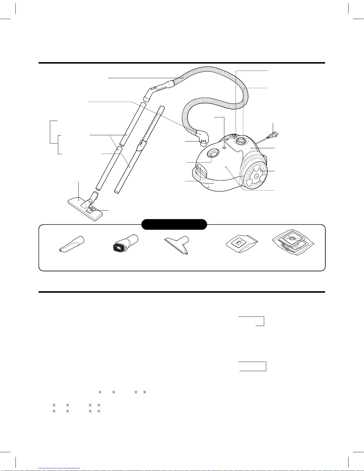
5. Attachments
• Nozzle : For cleaning wooden floor, the room floor and
carpet.
• Crevice Tool: for cleaning any crevice, inside corners
of window frames.However, do not use the crevice tool
more than 20 minutes because it may cause harm to
the motor.
• Dusting brush : For cleaning clothes curtains.
6. Close supervision is necessary when this
vacuum cleaner is used by or near children.
Children's carelessness may cause damage
to the cleaner or injure persons.
7. Air exhausted from the vacuum cleaner is
normally warm. But if extraordinarily hot air
is exhausted, check if the extension wands,
hose or dust bag is clogged or not.
8. Electric shock could occur if used outdoors
or on wet surfaces.
CAUTIONS
BEFORE ATTEMPTING TO SERVICE OR ADJUST ANY PART OF THE VACUUM CLEANER, DISCONNECT THE ELEC-
TRICAL POWER SUPPLY CORD FROM THE WALL OUTLET.
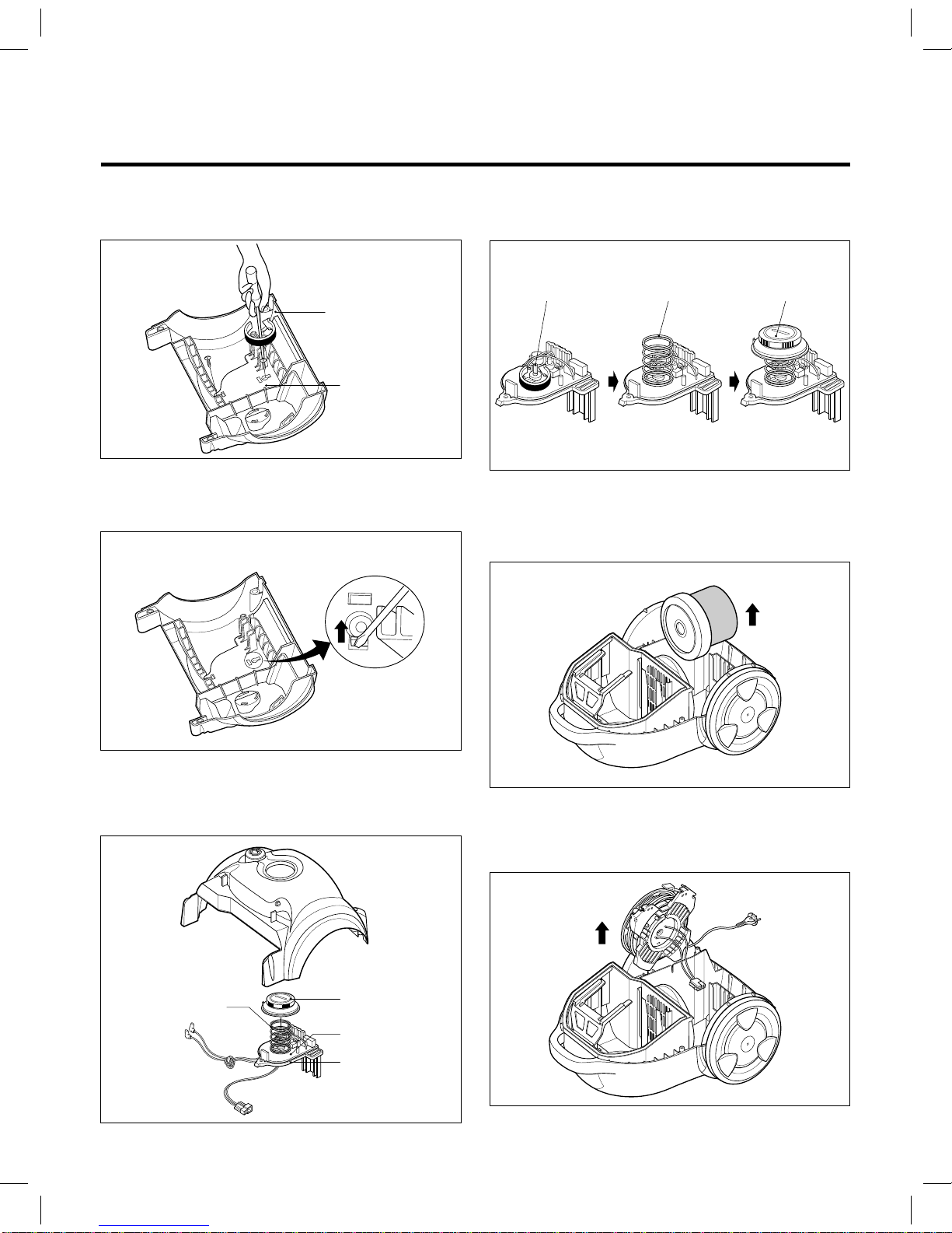
1. Motor exchange
1) Separate the body cover and body base by unfastening the screws.
2) Disconnect the lead wires.
3) Lift the old motor and replace it with a new one.
2. In case of exchanging other parts, refer to the exploded view.