LG DT6101SAU User manual

Instruction Manual
PartNO. 383EW5N001T(MFL30049915)
M
odel Numbers
DT6101SAU
DT6101SSA

EN 2
2
Instructions Manual
INDEX
RECOMMENDATIONS AND SUGGESTIONS......................................................................................................................3
CHARACTERISTICS..............................................................................................................................................................4
INSTALLATION......................................................................................................................................................................5
USE.........................................................................................................................................................................................7
MAINTENANCE......................................................................................................................................................................8

EN 3
3
RECOMMENDATIONS AND SUGGESTIONS
INSTALLATION
The manufacturer will not be held liable for any damages resulting from
incorrect or improper installation.
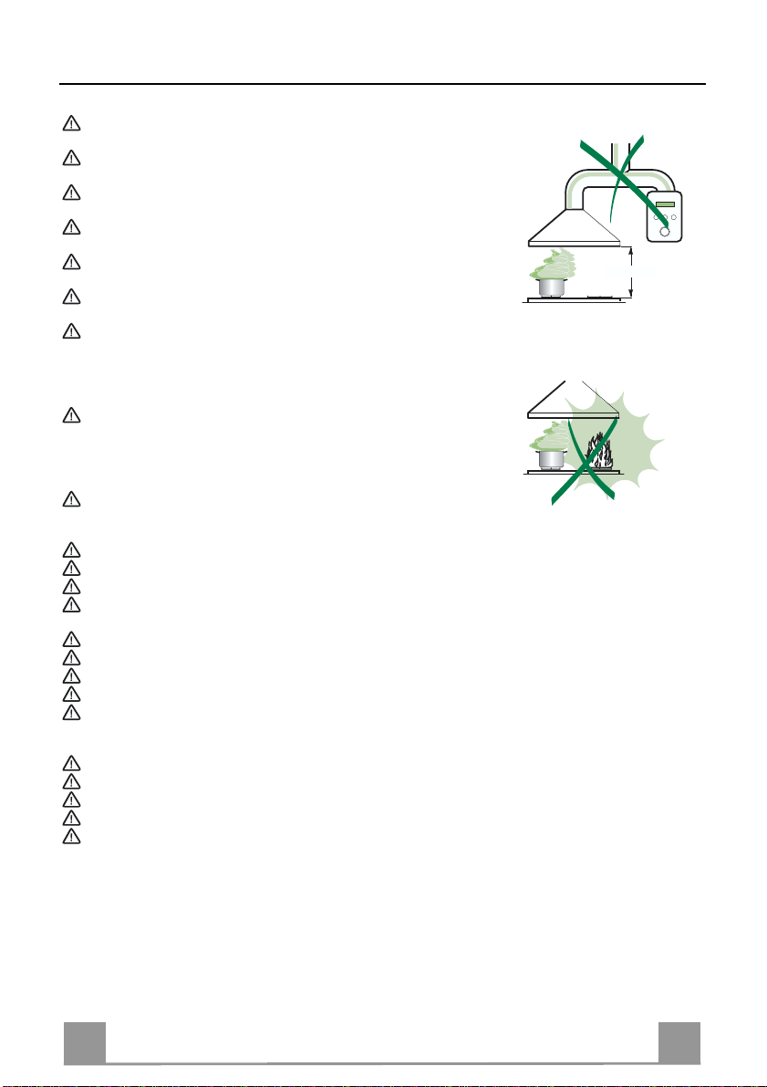
The minimum safety distance between the cooker top and the extractor
hood is 650mm.
Check that the mains voltage corresponds to that indicated on the rating
plate fixed to the inside ofthe hood.
For Class I appliances, check that the domestic power supply guarantees
adequate earthing.
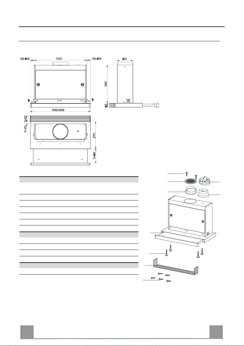
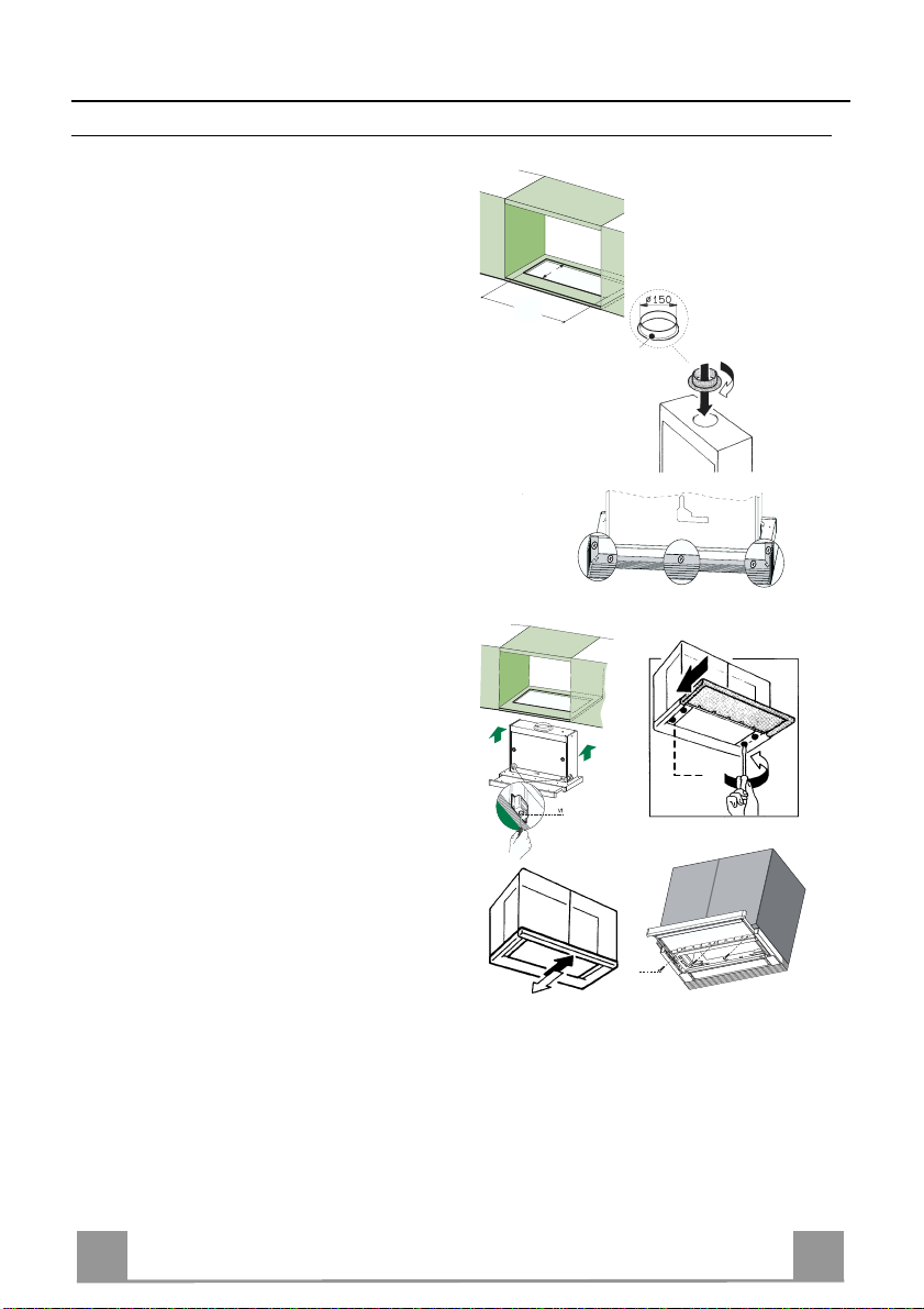
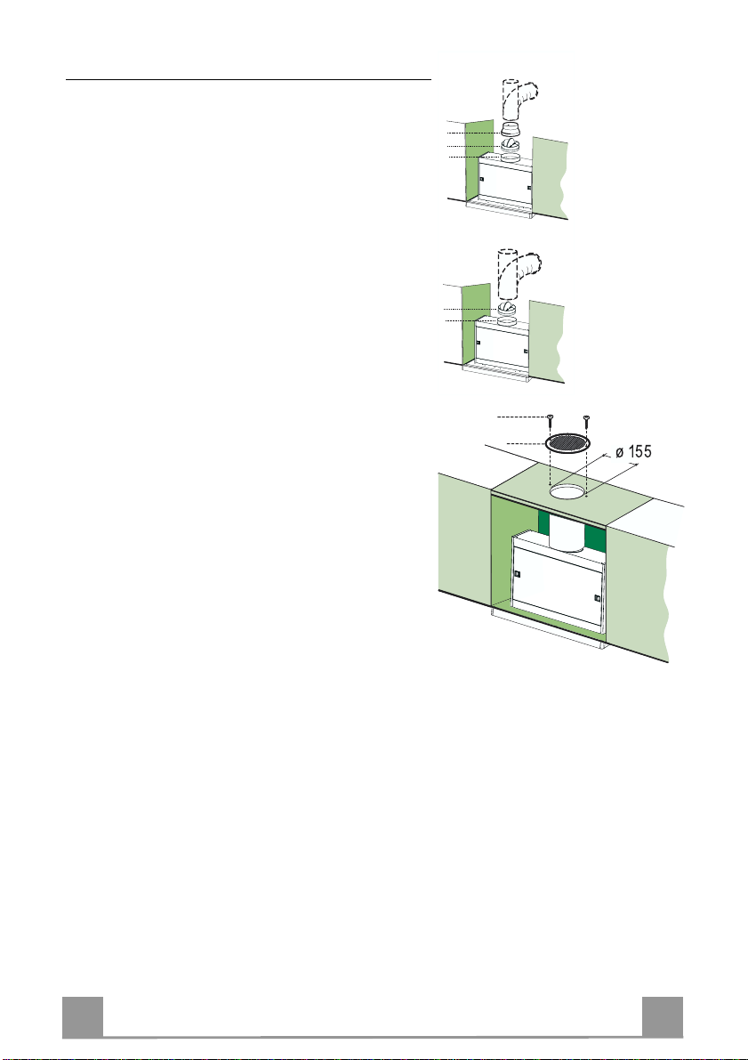
Connect the extractorto the exhaustflue through a pipeof minimumdiame-
ter 120 mm. The route of the flue must beas short as possible.
Do not connect the extractor hood to exhaust ducts carrying combustion
fumes (boilers, fireplaces, etc.).
If the extractor is used in conjunction with non-electrical appliances (e.g.
gas burning appliances), a sufficient degree of aeration must be guarante-
ed in the room in order to prevent the backflow of exhaust gas. The kitchen
must have an opening communicating directly with the open air in order to
guarantee the entry of clean air.
Installation of the extractor hood over a solid-fuel burner(coal, wood,etc.)
which could constitute a potential fire hazard (e.g. due to flying sparks) is
only permitted if the burner is equipped with an enclosed, non-removable
cover and all country-specific regulations are observed. This restriction do-
se not apply to gascookersand gashobs.
Regulations concerning the discharge of air have to be fulfilled.
USE
The extractor hood has been designed exclusivelyfor household use to eliminate kitchen smells.
Neveruse the hood for purposesotherthan for which ithas been designed.
Never leave high naked flames under the hood when it is in operation.
Adjust the flame intensity to direct it onto the bottom of the pan only, making sure that it does not engulf the si-
des.
Deep fat fryers must be continuously monitored during use: overheated oil can burst into flames.
The hood should not beused by children orpersons not instructed in its correct use.
Do not use the appliance if it is damaged in any way.
Neveroperate the extractor hood withouta grease filter.
Do not flambe food directly under theextractor hood.
MAINTENANCE
Switch off orunplug the appliance from the mains supplybefore carryingout anymaintenancework.
Cleanand/orreplace the Filters after the specified time period.
Clean the hood usinga damp cloth and a neutral liquid detergent.
Defective bulbs should be replaced immediately to preventthe remaining bulbsfrom overloading.
There is a fire riskif cleaning isnot carried outin accordance with the instructions.
650 mm min.

EN 4
4
CHARACTERISTICS
Dimensions
Components
Ref. Q.ty Product Components
11 Hood Body, complete with: Controls, Light, Blower,
Filters
81 Directional Air Outlet grille
91 Flange ø 150 mm
10a 1 Reducer Flange ø150-120 mm
10b 1 Damper
20 1 Closing element
Ref. Q.ty Installation Components
12a 4 Screws3,5 x16
12e 2 Screws2,9 x12,7
12f 5 Screws 2,9 x 9,5
Q.ty Documentation
1 Instruction Manual
9
1
12a
20
12f
10a
12e
810b

EN 5
5
INSTALLATION
Drilling the Support surface and Fitting the Hood
• The Hood can be fitted directly on the
lower surface of the Wall Units (650 mm
min. above the Cooker Top) using the snap-
on Side Supports.
• Make an opening on the lower surface of
the Wall Unit, as indicated. (fig.1)
• Choose the correct flange measure basing
on the air outlet diameter and insert it to the
upper air outlet opening. (fig.2)
• Screw the closing profile 20 onto the rear
part of the hood, using the screws 12f (2.9
x 9.5) provided. (fig.3)
• Open the sliding suction panel.
• Remove the metal grease filters one by one
after having disconnected the relative fas-
tening elements.
• Close the sliding suction panel again.
• Insert the Hood until the snap-on side sup-
ports click into place. (fig.4)
• Open the sliding suction panel.
• Lock in position by tightening the screws
Vf from underneath the Hood. (fig.4)
• If necessary, adjust the whole filter holder
unit and proceed as follows:
• Loosen the four adjustment screws Vr
and close the sliding panel again. (fig.5)
• Move the entire filter holder unit until it
is properly aligned with the wall unit.
(fig.6)
• Keeping the hood canopy still, open the
sliding panel and lock the adjustment
screws again. (fig.5)
• The hood can now be fastened to the
wall unit using the four screws 12a (3.5
x 16) provided. (fig.7)
• Replace the metal grease filters.
• Close the sliding suction panel again.
523
162
1
9
10a
10a
10b
2
4
V
5
6
12a
7
3

EN 6
6
Connections
DUCTED VERSION AIR EXHAUST SYSTEM
When installing the ducted version, connect the hood to
the chimney using either a flexible or rigid pipe ø 150
or 120mm, the choice of which is left to the installer.
• Install the Flange ø 150 mm 9.
• Install the Dumper 10b ø 150 on the Flange ø 150 9.
To install a ø 120
• Install a reducer Flange 10a on the Dumper 10b.
• Fix the pipe in position using sufficient pipe clamps
(not supplied).
• Remove any activated charcoal filters.
ø 120
10b
9
10a
ø 150
10b
9
RECIRCULATION VERSION AIR OUTLET
• Cut a hole ø 155 mm in the wall unit over the hood.
• Insert the flange 9on the hood body outlet.
• Connect the hood body outlet to the top part of the
wall unit using a rigid or flexible pipe ø 150 mm, to
be selected by the installer.
• Fix the pipe in position using sufficient pipe clamps
(not supplied).
• Fix the directional grille 8on the recirculation air
outlet using the 2 screws 12e (2,9 x 9,5) provided.
• Ensure that the activated charcoal filters have been
inserted.
12e
8
ELECTRICAL CONNECTION
• Connect the hood to the mains through a two-pole switch having a contact gap of at least 3
mm..

EN 7
7
USE
L
M
By pulling out the sliding panel it is possible to automatically activate all the hood functions.
By simply closing the sliding panel all the functions are switched off.
SWITCH FUNCTIONS
LLight Switches the lighting system on and off
MMotor Switches the extractor motor on and off
1. Low speed, used for a continuous and silent air change in the presence
of light cooking vapour.
2. Medium speed, suitable for most operating conditions, thanks to an op-
timum relation between hood performance and noise.
3. Maximum speed, suitable when the highest cooking vapour emission
has to be eliminated for longer periods.

EN 8
8
MAINTENANCE
Grease filters
CLEANING METAL CASSETTE GREASE FILTERS
• The filters must be cleaned every 2 months, or more frequently
in case of particularly heavy use of the hood. Filters can be
washed in a dishwasher.
• Pull out the sliding suction panel.
• Remove the filters one by one, after having disconnected the
relative fastening elements.
• Wash the filters, taking care not to bend them. Let them get dry
before refitting them. (The colour of the filter surface may
change throughout the time but this has no influence to the fil-
ter efficiency).
• When refitting the filters, make sure that the handle is visible
on the outside.
• Close the sliding suction panel.
Charcoal filter (Recycling version)
REPLACING CHARCOAL FILTERS
• These filters are not washable and cannot be regenerated, and
must be replaced approximately every four months or more
frequently by particularly heavy use.
• Pull out the sliding suction panel.
• Remove the grease filters.
• Remove the saturated carbon filter by releasing the fixing
hooks
• Replace the grease filters.
• Close the sliding suction panel.
Light Replacement
20 W Halogen lamp.
• Remove the metal terminals fixing the metal panel.
• Slide the metal panel out of one of the fastening clips. Lower
the unfastened part of the panel slightly, so that it can be com-
pletely removed.
• Extract the lamp from the Support.
• Replace with another of the same type, making sure that the
two pins are properly inserted in the lamp holder socket holes
• Replace the metal panel in reverse order.
When switched on, the halogen bulbs become very hot. Even
for some time after the bulbs have been switched off there is
still a risk of burns.


436003255_ver2
This manual suits for next models
1
Table of contents
Other LG Ventilation Hood manuals