LG LZ-H0106BA0 User manual

LG
Ventilation System
SERVICE MANUAL
LG
CAUTION
website http://www.lgservice.com
• BEFORE SERVICING THE UNIT, READ THE SAFETY
PRECAUTIONS IN THIS MANUAL.
• ONLY FOR AUTHORIZED SERVICE PERSONNEL.
MODELS: LZ-H0106BA0
LZ-H0156BA0
LZ-H0256BA0
LZ-H0506BA0
LZ-H0502BA0
LZ-H0806BA0
LZ-H0802BA0
LZ-H1006BA0
LZ-H1002BA0
LZ-H1506BA0
LZ-H1502BA0
LZ-H2006BA0
LZ-H2002BA0

2Ventilation System
Ventilation System Service Manual
TABLE OF CONTENTS
Safety Precautions..................................................................................................3
Standards for Model ..............................................................................................6
Product Standards .................................................................................................7
Descriptions for operation and functions .........................................................14
How to disassemble ............................................................................................17
Disassemble Diagram(Deal Drawing) and SVC Parts List ...............................22
Wiring Diagram ....................................................................................................32
Control Part Detailed Drawing ............................................................................36
Descriptions for Control Circuit .........................................................................38
Troubleshooting ...................................................................................................40
Feature Dimensions Diagram ..............................................................................47
Accessaries / Option ...........................................................................................52

Safety Precautions
Service Manual 3
Safety Precautions
To prevent injury to the user or other people and property damage, the following instructions must
be followed.
■Incorrect operation due to ignoring instruction will cause harm or damage. The seriousness is
classified by the following indications.
■Meanings of symbols used in this manual are as shown below.
This symbol indicates the possibility of death or serious injury.
This symbol indicates the possibility of injury or damage.
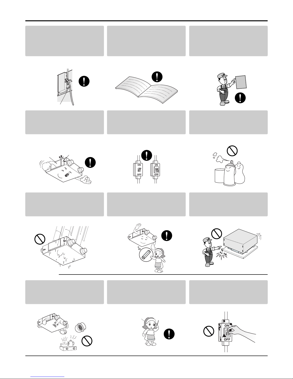
■For Installation
Be sure not to do.
Be sure to follow the instruction.
For electric working(wiring work),
contact Service Center or agency
you purchased the product.
• If you disassemble of repair
arbitrarily, it may cause fire or
electric shock.
Install in a place capable of the
product's weight.
• If the product is installed in a place
incapable of its weight, it may cause
an accident by its dropping.
Do not arbitrarily disassemble,
repair, or modify the product.
• It may cause fire or electric shock.
Be sure to undertake
grounding work.
• If you do not undertake grounding
work, it may cause electric shock.
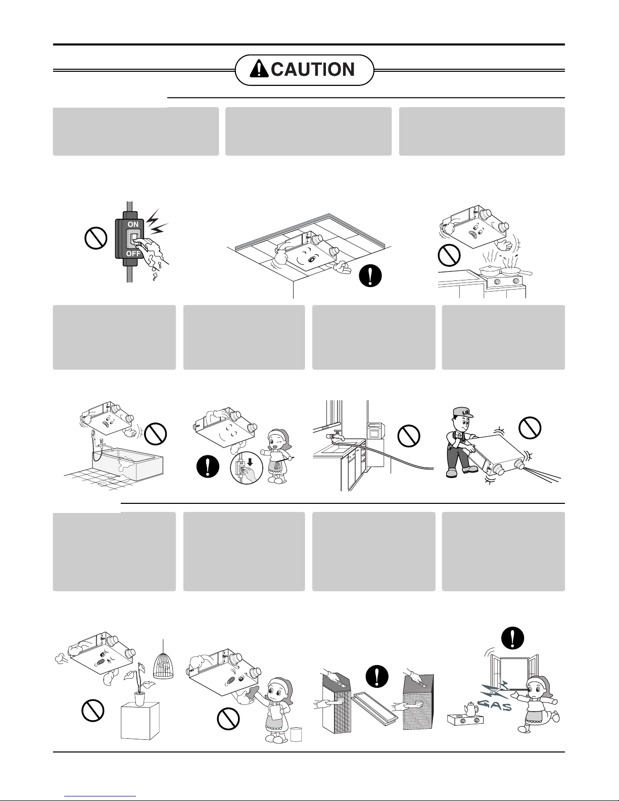
Use an netted inlet for
external air to prevent birds
from entering.
• Remove any clogs such as bird nest.
It may cause an oxygen deficiency in
a room.
Install the air intake where
polluted air can not be directly
sucked in.
• It may cause various accidents,
including suffocation, due to the
suction of harmful gasses(CO, etc.)
service center
solid surface
More than
1m apart

Safety Precautions
4Ventilation System
Wire with prescribed wire and
fix firmly to prevent it from
being pulled out by external
impact.
•Improper wiring and fixing may
cause fire.
Install in accordance with
installation manual.
•Improper installation may cause fire
and electric shock.
Electric works should be undertook
by an expert in accordance with
installation manual and the
indicated circuit diagram.
•Improper use of wires and electric
may cause fire and electric shock.
Be sure to install covers for
inspection and control box.
•If not, water and dust infiltrating into
the product may cause fire and
electric shock.
Be sure to install electric leakage
circuit breakers(ELB) and exclusive
switch(switch for electrics).
•If not, it may cause fire and electric
shock.
Do not keep flammable
materials or volatile gas near
the product.
•It may cause fire and breakdown.
Be sure to keep the product
out of water.
•It may cause electric shock and
breakdown.
Use a fuse in standardized
capacity.(Use a standardized
capacity fuse)
•It may cause fire and electric shock.
When unpacking, keep the
product from scratches and
sharp materials(object).
•If not, it may cause physical damage.
Keep out of inflammable.
•It may cause fire.
For the flooded product,
contact Service Center.
Do not use damaged electric
leakage circuit breaker or
switch.
•It may cause fire and electric shock.
■For use
cord clamp
Technical
standards
for electric
work
Maintenance Cover Control Box Cover
service center

Safety Precautions
Service Manual 5
Do not touch electric leakage
circuit breaker or switch with
wet hands.
•It may cause electric shock.
Install the product in an
insulated space.
•
If the product is installed outside of
insulating layer(surface), it may cause a
dew formation inside main body, electric
shock, and dropping of condensed water.
Do not install in oily place
such as kitchen and factory.
•It may cause breakdown due to oils
stained to filter or electric heat
exchanger.
Do not install in
humid place such as
bathroom.
•It may cause electric shock
and breakdown.
Switch the power off
during cleaning.
•It may cause fire and
electric shock.
Do not connect
grounding line to
window frame
(chassis) and tap.
•It has a danger of electric
shock.
Do not carry the
product alone.
•Otherwise, it may cause
physical damage.
Do not use for special
purposes and places
including animals and
plants, sensitive
equipment, and art pieces.
•Otherwise, it may cause
physical damage.
Do not use strong
detergent such as
wax or thinner in case
of cleaning, instead
use soft cloth.
•It ruins external
appearance due to
discoloration or scratches
on the product.
Clean filter and heat
exchanger regularly
with your gloves on.
•With a large quantity of
dust in the product, the
effect of ventilation may be
reduced. (it may not well
ventilated)
In case of gas leakage,
open the window to
change air(ventilate)
before using remote
controller.
•It may cause explosion
and fire.
■For Installation
■For use
solid surface
grounding line

Standards for Model
6Ventilation System
Standards for Model
Product Type
B: duct type hidden in ceiling
T: cassette type for ceiling
W: for window
Electrical Rating
6 : 1Ø, 220-240V, 50Hz
Function
A : Basic L : Nano Plasma + Clean(Wall mounted)
C : Plasma(Ceiling Cassette) G : Low Static Moter
Serial No.
Marking in a developed order.
Serial No.
Marking in a developed order.
Grade
S:Standard
D: Deluxe
Additional Functions
B: Base Model
M : possible to connect Multi V
Product Name
ZCON(Controller)
Ventilation Capacity(Ventilating Ability
Excluding the first digit of ventilating capacity per hour
50:500CMH
Heat Exchange Mode
H: Total heat(including humidity)
T: Sensible heat(temperature only)
Product classification
LZ : ventilation
LZ-H0506BA0

Product Standards
Service Manual 7
Product Standards
Item(format) Unit LZ-H0106BA0
Power Ø,V,Hz
Ventilation Mode -
Wind velocity -
Electric current A
Electricity consumption W
Airflow m3/h
External static press Pa
Temperature efficiency %
Enthalpy efficiency Heating %
Cooling %
Noise dB(A)
Air Filter -
Weight kg
Dimensions mm
1, 220-240, 50
Total heat ventilation
Super High High Low
0.32 0.3 0.28
68 60 50
100 100 70
40 35 30
78 78 80
68 68 70
58 58 60
28 26 20
Non-woven fabric filter
24
590(W) x 590(D) x 204(H)
Item(format) Unit LZ-H0156BA0
Power Ø,V,Hz
Ventilation Mode -
Wind velocity -
Electric current A
Electricity consumption W
Airflow m3/h
External static press Pa
Temperature efficiency %
Enthalpy efficiency Heating %
Cooling %
Noise dB(A)
Air Filter -
Weight kg
Dimensions mm
1, 220-240, 50
Total heat ventilation
Super High High Low
0.36 0.36 0.35
83 80 78
150 150 90
70 55 45
75 75 79
62 62 69
55 55 59
32 30 22
Non-woven fabric filter
24
590(W) x 590(D) x 204(H)

Product Standards
8Ventilation System
Item(format) Unit LZ-H0256BA0
Power Ø,V,Hz
Ventilation Mode -
Wind velocity -
Electric current A
Electricity consumption W
Airflow m3/h
External static press Pa
Temperature efficiency %
Enthalpy efficiency Heating %
Cooling %
Noise dB(A)
Air Filter -
Weight kg
Dimensions mm
1, 220-240, 50
Total heat ventilation
Super High High Low
0.55 0.5 0.34
130 115 80
250 250 150
65 50 40
80 80 85
70 70 78
64 64 68
32 28 21
Non-woven fabric filter
27
596(W) x 640(D) x 320(H)
Item(format) Unit LZ-H0506BA0
Power Ø,V,Hz
Ventilation Mode -
Wind velocity -
Electric current A
Electricity consumption W
Airflow m3/h
External static press Pa
Temperature efficiency %
Enthalpy efficiency Heating %
Cooling %
Noise dB(A)
Air Filter -
Weight kg
Dimensions mm
1, 220-240, 50
Total heat ventilation General ventilation
Super High High Low Super High High Low
1.51 1.39 1.06 1.51 1.39 1.06
260 225 200 260 225 200
500 500 320 500 500 320
150 60 28 150 60 28
82 82 86 - - -
79 79 83 - - -
76 76 80 - - -
34 32 25 34 32 25
Non-woven fabric filter
52
988(W) x 1,014(D) x 273(H)

Product Standards
Service Manual 9
Item(format) Unit LZ-H0502BA0
Power Ø,V,Hz
Ventilation Mode -
Wind velocity -
Electric current A
Electricity consumption W
Airflow m3/h
External static press Pa
Temperature efficiency %
Enthalpy efficiency Heating %
Cooling %
Noise dB(A)
Air Filter -
Weight kg
Dimensions mm
1, 220, 60
Total heat ventilation General ventilation
Super High High Low Super High High Low
1.25 1.07 0.9 1.25 1.07 0.9
258 235 195 258 235 195
500 500 320 500 500 320
200 70 28 200 70 28
82 82 86 - - -
79 79 83 - - -
76 76 80 - - -
34 32 25 34 32 25
Non-woven fabric filter
45
988(W) x 1,014(D) x 273(H)
Item(format) Unit LZ-H0806BA0
Power Ø,V,Hz
Ventilation Mode -
Wind velocity -
Electric current A
Electricity consumption W
Airflow m3/h
External static press Pa
Temperature efficiency %
Enthalpy efficiency Heating %
Cooling %
Noise dB(A)
Air Filter -
Weight kg
Dimensions mm
1, 220-240, 50
Total heat ventilation General ventilation
Super High High Low Super High High Low
2.8 2.7 2.6 2.8 2.7 2.6
405 360 320 405 360 320
800 800 660 800 800 660
200 110 60 200 110 60
79 79 82 - - -
70 70 75 - - -
65 65 70 - - -
36 34 30 36 34 30
Non-woven fabric filter
67
1,062(W) x 1,140(D) x 365(H)

Product Standards
10 Ventilation System
Item(format) Unit LZ-H0802BA0
Power Ø,V,Hz
Ventilation Mode -
Wind velocity -
Electric current A
Electricity consumption W
Airflow m3/h
External static press Pa
Temperature efficiency %
Enthalpy efficiency Heating %
Cooling %
Noise dB(A)
Air Filter -
Weight kg
Dimensions mm
1, 220, 60
Total heat ventilation General ventilation
Extremely strong
Strong
Weak(mild)
Extremely strong
Strong
Weak(mild)
3.1 3.0 2.5 3.1 3.0 2.5
585 555 470 585 555 470
800 800 660 800 800 660
200 110 60 200 110 60
79 79 82 - - -
70 70 75 - - -
65 65 70 - - -
36 34 30 36 34 30
Non-woven fabric filter
67
1,062(W) x 1,140(D) x 365(H)
Item(format) Unit LZ-H1006BA0
Power Ø,V,Hz
Ventilation Mode -
Wind velocity -
Electric current A
Electricity consumption W
Airflow m3/h
External static press Pa
Temperature efficiency %
Enthalpy efficiency Heating %
Cooling %
Noise dB(A)
Air Filter -
Weight kg
Dimensions mm
1, 220-240, 50
Total heat ventilation General ventilation
Extremely strong
Strong
Weak(mild)
Extremely strong
Strong
Weak(mild)
3.0 2.9 2.6 2.8 2.7 2.4
560 540 470 560 540 470
1,000 1,000 800 1,000 1,000 800
160 90 50 200 110 60
75 75 78 - - -
66 66 71 - - -
61 61 66 - - -
37 35 31 37 35 31
Non-woven fabric filter
67
1,062(W) x 1.140(D) x 365(H)

Product Standards
Service Manual 11
Item(format) Unit LZ-H1002BA0
Power Ø,V,Hz
Ventilation Mode -
Wind velocity -
Electric current A
Electricity consumption W
Airflow m3/h
External static press Pa
Temperature efficiency %
Enthalpy efficiency Heating %
Cooling %
Noise dB(A)
Air Filter -
Weight kg
Dimensions mm
1, 220, 60
Total heat ventilation General ventilation
Extremely strong
Strong
Weak(mild)
Extremely strong
Strong
Weak(mild)
3.5 3.4 2.9 3.5 3.4 2.9
675 655 560 675 655 560
1,000 1,000 800 1,000 1,000 800
200 110 60 200 110 60
75 75 78 - - -
66 66 71 - - -
61 61 66 - - -
37 35 31 37 35 31
Non-woven fabric filter
67
1,062(W) x 1,140(D) x 365(H)
Item(format) Unit LZ-H1506BA0
Power Ø,V,Hz
Ventilation Mode -
Wind velocity -
Electric current A
Electricity consumption W
Airflow m3/h
External static press Pa
Temperature efficiency %
Enthalpy efficiency Heating %
Cooling %
Noise dB(A)
Air Filter -
Weight kg
Dimensions mm
1, 220-240, 50
Total heat ventilation General ventilation
Extremely strong
Strong
Weak(mild)
Extremely strong
Strong
Weak(mild)
5.6 5.4 5.2 5.6 5.4 5.2
950 925 795 950 925 795
1,500 1,500 1,200 1,500 1,500 1,200
200 110 60 200 110 60
79 79 82 - - -
70 70 75 - - -
65 65 70 - - -
39 37 33 39 37 33
Non-woven fabric filter
146
1,313(W) x 1,140(D) x 737(H)

Product Standards
12 Ventilation System
Item(format) Unit LZ-H2006BA0
Power Ø,V,Hz
Ventilation Mode -
Wind velocity -
Electric current A
Electricity consumption W
Airflow m3/h
External static press Pa
Temperature efficiency %
Enthalpy efficiency Heating %
Cooling %
Noise dB(A)
Air Filter -
Weight kg
Dimensions mm
1, 220-240, 50
Total heat ventilation General ventilation
Super High High Low Super High High Low
6.0 5.8 5.2 5.6 5.4 4.8
1,020 970 860 1,020 970 860
2,000 2,000 1,600 2,000 2,000 1,600
160 90 50 200 110 60
75 75 78 - - -
66 66 71 - - -
61 61 66 - - -
42 38 33 42 38 33
Non-woven fabric filter
146
1,313(W) x 1,140(D) x 737(H)
Item(format) Unit LZ-H1502BA0
Power Ø,V,Hz
Ventilation Mode -
Wind velocity -
Electric current A
Electricity consumption W
Airflow m3/h
External static press Pa
Temperature efficiency %
Enthalpy efficiency Heating %
Cooling %
Noise dB(A)
Air Filter -
Weight kg
Dimensions mm
1, 220, 60
Total heat ventilation General ventilation
Super High High Low Super High High Low
6.2 6.0 5.0 6.2 6.0 5.0
1,190 1,151 960 1,190 1,151 960
1,500 1,500 1,280 1,500 1,500 1,280
200 110 70 200 110 70
79 79 82 - - -
70 70 75 - - -
65 65 70 - - -
39 37 33 39 37 33
Non-woven fabric filter
146
1,313(W) x 1,140(D) x 737(H)

Product Standards
Service Manual 13
Item(format) Unit LZ-H2002BA0
Power Ø,V,Hz
Ventilation Mode -
Wind velocity -
Electric current A
Electricity consumption W
Airflow m3/h
External static press Pa
Temperature efficiency %
Enthalpy efficiency Heating %
Cooling %
Noise dB(A)
Air Filter -
Weight kg
Dimensions mm
1, 220, 60
Total heat ventilation General ventilation
Super High High Low Super High High Low
7.0 6.8 5.8 7.0 6.8 5.8
1,344 1,306 1,122 1,344 1,306 1,122
2,000 2,000 1,600 2,000 2,000 1,600
200 110 70 200 110 70
75 75 78 - - -
66 66 71 - - -
61 61 66 - - -
42 38 33 42 38 33
Non-woven fabric filter
146
1,313(W) x 1,140(D) x 737(H)

Descriptions for operation and functions
14 Ventilation System
Descriptions for operation and functions
Main Body
1
5
6
2
4
3
Models: LZ-H0106BA0 / LZ-H0156BA0
1. Blower for Air Supply
A blower for sucking outside air.
2. Control Box
3. Blower for Exhausting
A blower for draining polluted air outside.
4. Maintenance cover
5. Total Heat Exchanger
Exchanges temperature and moisture between air
supply air and exhaust air.
6. Air Filter
Prevents clogging of the Total heat exchanger due to
❈The figure of Total heat Exchanger can be different by the Product Model.
15
4
6
2
3
1. Air Filter
Prevents clogging of the Total heat exchanger due to
dust.
2. Total Heat Exchanger
Exchanges temperature and moisture between air
supply air and exhaust air.
3. Blower for Exhausting
A blower for draining polluted air outside.
4. Control Box
5. Blower for Air Supply
A blower for sucking outside air.
6. Maintenance cover
Models: LZ-H0256BA0

Descriptions for operation and functions
Service Manual 15
1
2
3
4
5
6
7
8
Models: LZ-H0506BA0 / LZ-H0502BA0
1. Maintenance Cover
2. Air Filter
It prevents dust from clogging in Total Heat Exchanger.
3. Total Heat Exchanger
It changes temperature and humidity between
Supplying Air and exhausted air.
4. Blower for Exhausting Air
It is a fan for discharging the contaminated air to
outdoor.
5. Control box
6. Blower for Exhausting Air
It is a fan for inhaling exterior air into an indoor space.
7. Damper plate(board)
It converts exchanging mode between total heat
ventilation and general ventilation.
8. Total Heat Exchanger holder
It is used in guiding for the installation of Total Heat
Exchanger.
❈The form of Total Heat Exchanger varies according to models.
1
5
6
7
8
2
3
4
Models: LZ-H0806BA0 / LZ-H0802BA0 / LZ-H1002BA0 / LZ-H1006BA0
1. Maintenance Cover
2. Air Filter
It prevents dust from clogging in Total Heat Exchanger.
3. Total Heat Exchanger
It changes temperature and humidity between
Supplying Air and exhausted air.
4. Blower for Exhausting Air
It is a fan for discharging the contaminated air to
outdoor.
5. Control box
6. Blower for Supplying Air
It is a fan for inhaling exterior air into an indoor space.
7. Damper plate(board)
It converts exchanging mode between total heat
ventilation and general ventilation.
8. Total Heat Exchanger holder
It is used in guiding for the installation of Total Heat
Exchanger.

Descriptions for operation and functions
16 Ventilation System
1
2
3
4
5
6
7
8
Models: LZ-H1506BA0 / LZ-H1502BA0 / LZ-H2006BA0 / LZ-H2002BA0
(Ventilation System remote controller ZCON-BS2) remote controller is a separate purchase.
1. Maintenance Cover
2. Air Filter
It prevents dust from clogging in Total Heat Exchanger.
3. Total Heat Exchanger
It changes temperature and humidity between
Supplying Air and exhausted air.
4. Blower for Exhausting Air
It is a fan for discharging the contaminated air to
outdoor.
5. Control box
6. Blower for Supplying Air
It is a fan for inhaling exterior air into an indoor space.
7. Damper plate(board)
It converts exchanging mode between total heat
ventilation and general ventilation.
8. Total Heat Exchanger holder
It is used in guiding for the installation of Total Heat
Exchanger.
❈The form of Total Heat Exchanger varies according to models.
❈Some functions may not work depending on models. (according to models).
LCD remote controller
Program set
Room Temp
HI
MED
LO
Timer
On
Set no. Time
Off
01 03 05 07 09 11 13 15 17 19 21 23
Operation unit
ZONE
1234
AUTO SWING
AUTO
JET
Heater
Defrost
Preheat
Humidify
Filter Out door
Time
OPERATION SET TEMP FAN SPEED
SUB FUNCTION
Timer
Program
Hour
Cancel
Week Holiday
Set/Clr
PLASMA
RESET
Min
1
2
5
6
7
8
9
10
11
12
13
3
4
When the cover is open,
1. Display Screen
2. Heater Button
3. Button for time setting/ canceling, and weekend
setting/date selecting/ weekend selecting
4. Play/ Stop Button
5. Delaying time Button
6. Quick ventilation Button
7. Ventilating Mode Button
8. Air flow selection Button
9. Humidification Button
10. Power-saving/filter cleaning Button
11. Plasma Button
12. Time Reset Button

How to disassemble
Service Manual 17
Models: LZ-H0106BA0 / LZ-H0156BA0
How to disassemble
In case of service, operate through inspecting tool(hole) installed on the surface of ceiling.
For main part disassembly, follow the instructions below.
Control Box
•Unscrew the control box cover, and disassemble.
Total Heat Exchanger, Filter
•Take the Maintenance Cover off, and take them out. (in
case that the Maintenance Cover is screwed up,
unscrew it first.)
•Be careful of sharp area when taking the Air Filter out.
•Be careful not to drop the Total Heat Exchanger from
the main body when detaching.
Fan
•Take the fan out after taking the Maintenance Cover off.
(in case that the Maintenance Cover is screwed up,
unscrew it first.)
•Be careful of sharp area when taking the fan out.
control box cover
screw
screw
Maintenance
Cover

How to disassemble
18 Ventilation System
Models: LZ-H0256BA0
Control Box
•Unscrew the control box cover, and disassemble.
Total Heat Exchanger, Filter
•Take the Maintenance Cover off, and take them out. (in
case that the Maintenance Cover is screwed up,
unscrew it first.)
•Be careful of sharp area when taking the Air Filter out.
•Be careful not to drop the Total Heat Exchanger from
the main body when detaching.
Fan
•Take the fan out after taking the Maintenance Cover off.
(in case that the Maintenance Cover is screwed up,
unscrew it first.)
•Be careful of sharp area when taking the fan out.
Screw Control box cover
Maintenance
Cover
Main Body
Setting Knob
Total Heat
Exchanger
Clamp Cord
In case of service, operate through inspecting tool(hole) installed on the surface of ceiling.
For main part disassembly, follow the instructions below.

How to disassemble
Service Manual 19
Models: LZ-H0506BA0 / LZ-H0502BA0
Control Box
•Unscrew the control box cover, and disassemble.
Total Heat Exchanger, Filter
•Take the Maintenance Cover off, and take them out. (in
case that the Maintenance Cover is screwed up,
unscrew it first.)
•Be careful of sharp area when taking the Air Filter out.
•Be careful not to drop the Total Heat Exchanger from
the main body when detaching.
Fan
•Take the fan out after taking the Maintenance Cover off.
(in case that the Maintenance Cover is screwed up,
unscrew it first.)
•Be careful of sharp area when taking the fan out.
Control box cover
Screw
Maintenance Cover
Main body
Main body
In case of service, operate through inspecting tool(hole) installed on the surface of ceiling.
For main part disassembly, follow the instructions below.

How to disassemble
20 Ventilation System
Models: LZ-H0806BA0 / LZ-H0802BA0 / LZ-H1006BA0 / LZ-H1002BA0
Control Box
•Unscrew the control box cover, and disassemble.
Total Heat Exchanger, Filter
•Take the Maintenance Cover off, and take them out. (in
case that the Maintenance Cover is screwed up,
unscrew it first.)
•Be careful of sharp area when taking the Air Filter out.
•Be careful not to drop the Total Heat Exchanger from
the main body when detaching.
Fan
•Take the fan out after taking the Maintenance Cover off.
(in case that the Maintenance Cover is screwed up,
unscrew it first.)
•Be careful of sharp area when taking the fan out.
Control box cover
Screw
Maintenance Cover
Main body
Main body
In case of service, operate through inspecting tool(hole) installed on the surface of ceiling.
For main part disassembly, follow the instructions below.
This manual suits for next models
12
Table of contents
Other LG Ventilation Hood manuals