LIAD ColorSave 1000ST-INJ User manual

LIAD Weighing and Control Systems Ltd.
Sky Street, POB 10, Misgav Industrial Park, M.P. Misgav 2017400, Israel
ColorSave 1000ST-INJ
Single-component masterbatch/additive gravimetric
feeder for injection molding machines
User Manual
Edited: 01/17

ColorSave 1000ST-INJ user manual
LIAD Weighing and Control Systems Ltd 2
TABLE OF CONTENTS
Equipment Handling And Safety ............................................................................................4
1.0 Introduction........................................................................................................................5
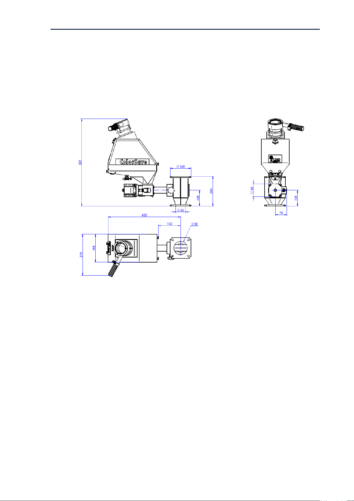
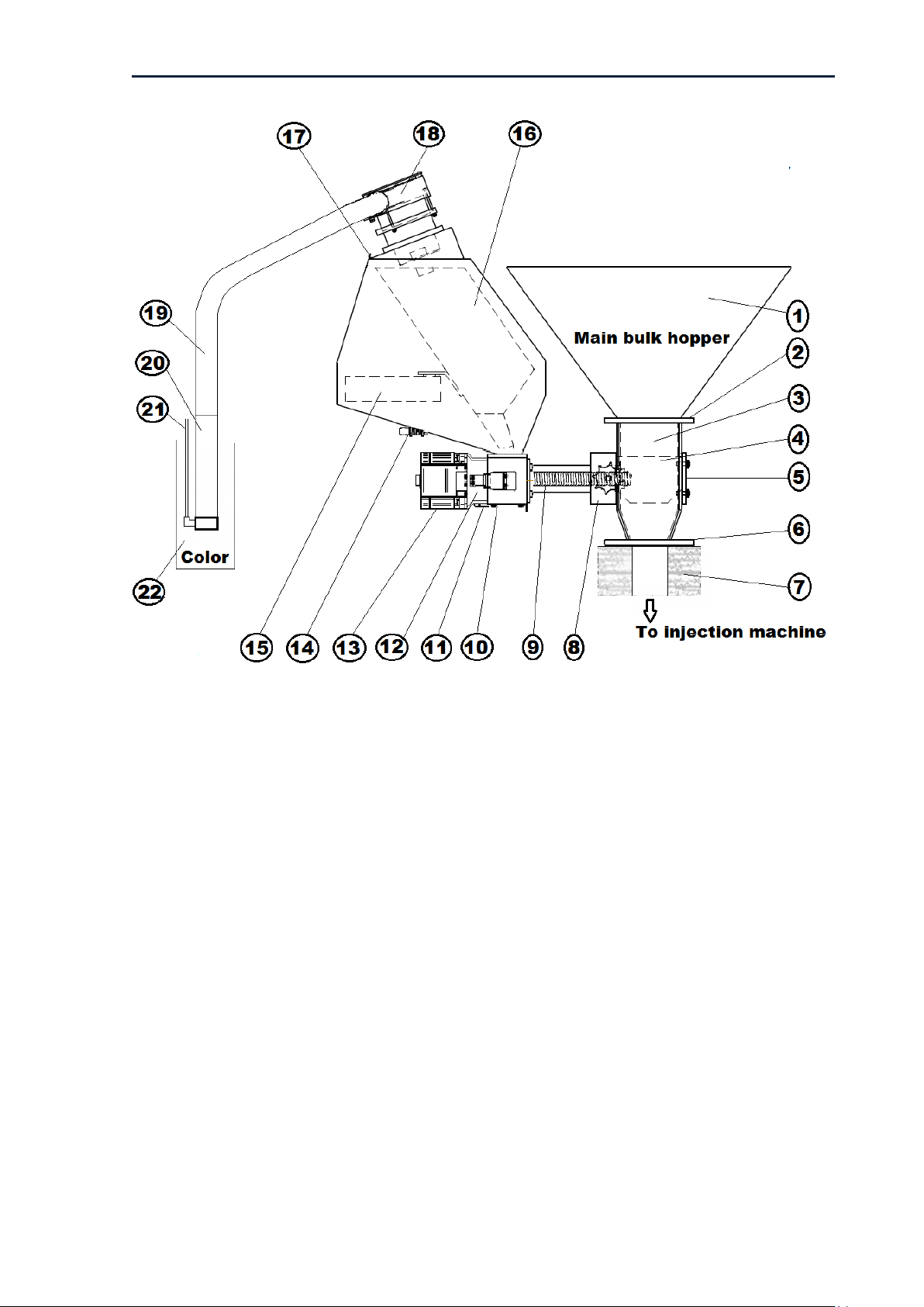
2.0 Product Overview ..............................................................................................................6
2.1 Feeding System .............................................................................................................6
2.2 Feeding (dosing) Screws ..............................................................................................8
2.3 Control Unit ....................................................................................................................9
2.3.1 ColorSave 1000ST-INJ Controller Front View ....................................................9
2.3.2 ColorSave 1000ST-INJ Controller Rear View .....................................................9
3.0 Installation........................................................................................................................10
3.1 General Safety Notes And Warnings ........................................................................10
3.2 Mechanical Installation ...............................................................................................11
3.2.1 Mounting To The Injection-Molding Machine Throat .....................................11
3.2.2 Releasing The Load Cell......................................................................................11
3.2.3 Venturi Loader Installation .................................................................................12
3.2.4 Control Unit Mounting .........................................................................................12
3.3 Electrical Installation...................................................................................................13
3.3.1 Connections...........................................................................................................13
3.3.2 Sensor Cable Wiring Options..............................................................................14
4.0 Operation..........................................................................................................................15
4.1 General..........................................................................................................................15
4.1.1 Operation Modes..................................................................................................15
4.1.2 MB/AD Feeding Modes ........................................................................................16
4.1.3. Speeds Displayed On Main Screen...................................................................16
4.1.4 Gram Per Rotation ...............................................................................................17
4.2 Starting Sequence .......................................................................................................18
4.2.1 Main Screen For Mode "0" (Gravimetric mode, with machine dosing time)
..........................................................................................................................................18
4.2.2 Main Screen For Mode "1" (Gravimetric mode, with constant dosing time)
..........................................................................................................................................18
4.2.2.1 Changing Screw Feeding Time In Mode "1".................................................19
4.2.3 Main Screen For Mode "2" (Volumetric mode, with machine dosing time) 19
4.2.3.1 Changing Screw Speed In Mode "2"..............................................................19
4.2.4 Main Screen For Mode "3" (Volumetric mode, with constant dosing time) 20
4.2.4.1 Changing Screw Speed And Feeding Time In Mode "3" ............................20
4.2.4.2 Changing Screw Revolutions And Speed In Micro Mode "3" .....................21
4.3 Configuration Parameters Setup ...............................................................................22
4.3.1 Setting Parameter Values ...................................................................................22
4.3.2 Setting Installed Screw Number ........................................................................22
4.3.3 Setting Desired Operation Mode........................................................................23
4.3.4 Setting Max/Min Hopper Weight Parameters ..................................................23
4.3.5 Setting Recipe Mode............................................................................................23
4.3.6 Setting Cavity Mode.............................................................................................24
4.3.7 Setting Permitted Tolerance...............................................................................24
4.3.8 Setting Alarm Output Type.................................................................................24
4.3.9 Gravimetric/Volumetric Switch...........................................................................25
4.4 Accumulated Data Display .........................................................................................26

ColorSave 1000ST-INJ user manual
LIAD Weighing and Control Systems Ltd 3
4.5 Failure Alarms ..............................................................................................................27
4.5.1 “No Material” Alarm .............................................................................................27
4.5.2 “Over/Under Speed (dose)” Alarms ..................................................................27
4.5.3 “Calibration Failure” Alarms................................................................................28
4.5.4 “Feed Deviation” Alarm .......................................................................................28
4.5.5 “No Rotation” Alarm ............................................................................................29
4.5.6 “Out Of Tolerance” Alarm ...................................................................................29
4.5.7 Alarm Output (J2) ................................................................................................29
4.5.8 Alarm List ..............................................................................................................29
4.5.9 Alarm Log ..............................................................................................................29
4.6 Working With Recipes.................................................................................................30
4.6.1 Modify Recipe .......................................................................................................30
4.6.2 Select Recipe ........................................................................................................31
4.7 Working With Cavities.................................................................................................31
4.7.1 Change Number Of Cavities ...............................................................................31
4.7.2 Setting Number Of Cavities In The Recipe ......................................................32
5. Maintenance .......................................................................................................................33
5.1 Password.......................................................................................................................33
5.2 Static Calibration..........................................................................................................33
5.3 Dynamic Calibration ....................................................................................................33
5.4 Emptying And Cleaning ..............................................................................................34
5.5 Replacing The Dosing Screw .....................................................................................34
5.6 Emptying / Refilling The Feeding Screw ..................................................................35
5.7 Moving Feeder To Another Injection Machine Or Replacing Controller..............35
5.8 Troubleshooting...........................................................................................................36
5.9 Control Parameters .....................................................................................................38
5.10 Communication Option.............................................................................................39
5.11 Trends .........................................................................................................................40
5.11.1 Trend Speed .......................................................................................................40
5.11.2 Trend Percentage ..............................................................................................40
6 Technical Data.....................................................................................................................41
6.1 Technical Features ......................................................................................................41
6.2 Environmental Conditions ..........................................................................................42
Appendix A: Load Cell Protection Device............................................................................43
Appendix B: Static Calibration..............................................................................................45
1. General............................................................................................................................45
2. Calibration Process ........................................................................................................45
Appendix C: Dynamic Calibration ........................................................................................48
1. General............................................................................................................................48
2. Calibration Process ........................................................................................................48
Appendix D: Electrical Drawings ..........................................................................................50
Appendix E: EC-Declaration Of Conformity........................................................................55

ColorSave 1000ST-INJ user manual
LIAD Weighing and Control Systems Ltd 4
EQUIPMENT HANDLING AND SAFETY
Please read this first!
General
This manual has been written to enable operators to use the machine correctly. Always keep the
manual at hand and always follow the instructions.
The operator is completely responsible for the operating safety of the system, and therefore all
operators must have full knowledge of its proper use.
Any use in a manner not specified in the user manual or any attempt by the user or non-authorized
personnel to disassemble or modify the machine shall render the warranty invalid and the
manufacturer shall not be responsible for any damage to persons or property.
The equipment must be installed, operated, and maintained only by skilled personnel who have
read and understood this manual.
LIAD is not responsible in any way for the quality of the products produced by the injection
machine on which LIAD equipment has been installed. Product quality is the sole responsibility of
the customer.
All technical data contained in this manual are the exclusive property of LIAD Weighing and
Control Systems Ltd. and must be considered as confidential. Therefore no reproduction or
publication of this manual, or any part thereof, is allowed without written authorization by the
manufacturer. Moreover, this manual shall not be used for purposes other than those connected to
installation, use and maintenance of this equipment.
Safety
▪Unqualified persons should not be allowed to handle this equipment.
▪Non-compliance with the installation and operation instructions may result in severe personal
injury or substantial property damage.
▪In order to avoid electric shocks, make sure that you first make all necessary connections,
before connecting the equipment to the mains. Also, make sure that it is protected by
effective short-circuit and over-voltage devices, and any other means required to protect the
operator, and that there is an effective earth (ground) connection to the device.
▪Only qualified persons should perform any installation, maintenance, and repair work, and
only when the system is fully disconnected from the power supply mains. For the ensured
safety of you and your colleagues:
oObserve all instructions for operation and maintenance of this equipment
oPay attention to all warning signs!
oLearn the equipment's safety devices and make sure they are in working order before and
after every operation
oDo not operate the equipment if the safety devices are not operating correctly
Please contact your LIAD representative if you have any questions about the safety of this system.

ColorSave 1000ST-INJ user manual
LIAD Weighing and Control Systems Ltd 5
1.0 INTRODUCTION
ColorSave 1000ST-INJ is a single-component, gravimetric masterbatch/additive feeder for injection
molding machines.
During normal operation, the device controls the weight of the masterbatch/additive (from now on
referred to as MB/AD)fed into the machine with each injection shot, using a loss-in-weight method.
By continuously measuring the weight of the material in its hopper, the system immediately detects
any deviation from the preset MB/AD weight, and automatically corrects this by regulating the current
(rpm) of the feeding screw.
If required, the feeder can operate in “constant” (non-regulated) current mode - the motor works at a
pre-selected current (rpm) without being regulated by the controller.
The MB/AD is fed directly into the injection machine’s feeding throat through a neckpiece adapter.
The ColorSave 1000ST-INJ is fitted with a feeding screw; there are 5 standard types of screw for
varying dosing ranges. Note that correct selection of the screw is instrumental in obtaining very high
accuracy.
The feeder can be equipped with an integral Venturi loader, which automatically refills the hopper
whenever its contents fall below a predefined minimum weight.
The feeder’s entire operation is automatically controlled by a powerful, sophisticated, yet easy-to-
operate control unit.

ColorSave 1000ST-INJ user manual
LIAD Weighing and Control Systems Ltd 6
2.0 PRODUCT OVERVIEW
2.1 Feeding System
Fig. 1: General View and Dimensions

ColorSave 1000ST-INJ user manual
LIAD Weighing and Control Systems Ltd 7
Fig. 2: Mechanical Details
1) Main bulk hopper
2) Neckpiece top flange
3) Neckpiece
4) Bridge
5) Sight glass
6) Neckpiece bottom flange
7) Injection machine throat
8) Adding flange
9) Feeding screw
10) Emptying aperture
11) Screw fixating clip
12) Support flange
13) STEP motor
14) Load cell protection device
15) Load cell
16) MB/AD hopper
17) Quick release latch
18) MB/AD loading inlet
19) Flexible loading pipe
20) Venturi suction tube
21) Pneumatic air inlet
22) MB/AD container

ColorSave 1000ST-INJ user manual
8
2.2 Feeding (dosing) Screws
Choosing the right feeding screw is essential for achieving the required dosing accuracy. The
following table shows the screws available and their material dosing capacities:
Feeding Screw
Capacity
0
Micro-capacity
1-3 pellets/shot
1.1
Low-capacity- standard
0.1 –4 Kg/hr
1
Low-capacity –smooth*
0.1 –4 Kg/hr
2
Medium-capacity
0.2 –10 Kg/hr
3
High -capacity
0.4 –18 Kg/hr
4A
Extra-capacity (3/4")
0.6 –35 Kg/hr
* for particular materials –consult with your LIAD representative
Notes:
a) Indicated screw capacity values are typical for free flowing granular 0.7 Kg/L bulk density
materials. Actual capacity depends on actual material features such as bulk density, flow ability,
pellet size etc., and also on the hopper volume.
b) The identification number is marked on each screw (micro screw is marked with "C").
c) Please consult with LIAD regarding higher capacity screws.

ColorSave 1000ST-INJ user manual
9
J4: Communication port
2.3 Control Unit
2.3.1 ColorSave 1000ST-INJ Controller Front View
Fig. 3: ColorSave 1000ST-INJ
controller front view
2.3.2 ColorSave 1000ST-INJ Controller Rear View
Fig. 4: ColorSave 1000ST-INJ controller rear view
Gravimetric/volumetric
switch
J1: Load cell input
J2: Alarm output
J5: STEP motor control output
J3: Sensor input
S1: On/Off power inlet
P1: Pneumatic valve

ColorSave 1000ST-INJ user manual
10
3.0 INSTALLATION
3.1 General Safety Notes And Warnings
This manual contains information required for installation.
Adherence to the safety notes is mandatory. Non-compliance will invalidate your warranty.
When you receive the equipment, you should immediately check whether any damage occurred
during transport. If this is the case, please consult your agent before installation.
Warning
Persons who are not qualified should not be allowed to handle this equipment/system. Non-
compliance with the installation and operation instructions can result in severe personal injury or
substantial property damage. Only qualified personnel should be allowed to work on this
equipment/system.
In order to avoid electric shock, make sure that you first make all necessary connections, before
connecting the equipment to the mains. Also, make sure that it is protected by effective short-circuit
and over-voltage devices, and any other means required to protect the operator, and that there is an
effective earth (ground) connection to the device.
Caution: The motor has a permanent magnetic field. Never exceed Imax (6A).
Any installation, maintenance and repair intervention must be performed only by skilled personnel,
and only when the equipment/system is disconnected from the power supply mains.

ColorSave 1000ST-INJ user manual
11
3.2 Mechanical Installation
3.2.1 Mounting To The Injection-Molding Machine Throat
The neckpiece adapter (standard hexagonal version shown here) is used to connect the ColorSave
1000ST-INJ to the injection molding machine:
Fig. 5: Standard hexagonal neckpiece
In order to mount the ColorSave 1000ST-INJ into the injection molding machine please do the
following (refer to Fig. 2):
a) Install the neckpiece in position, between the main hopper and the injection machine’s feeding
throat, and fasten with its screws.
b) Connect the feeder to the adding flange (8) and fasten it with the quick-release star knob.
3.2.2 Releasing The Load Cell
The load cell is extremely sensitive and should always be handled carefully.
When the unit leaves the factory, the load cell is locked by its protecting device, to prevent any
damage to the load cell during transportation and installation.
After installation and before operating the feeder, release the limiting pin of the protecting device
from its "locked position" to "unlocked position"; otherwise the load cell will not be able to function.
See Appendix A: Load Cell Protection Device for unlocking instructions after installation.
Important:
Always relock the safety device whenever the ColorSave 1000ST-INJ is dismantled from the injection
machine and is being moved to another location or machine.
Note that there is no guarantee for the load cell in case of any mechanical damage, or damage
caused by an overload.

ColorSave 1000ST-INJ user manual
12
3.2.3 Venturi Loader Installation
Fig. 6: Venturi loader
a) Connect the Venturi suction tube (19) to the feeder’s MB/AD loading inlet (17) with the flexible 25
mm dia. loading pipe (18).
Note: The maximum pipe length should not exceed 3 meters and the maximum difference
between the end of the Venturi suction tube and the top of the feeder-loading inlet should not
exceed 2.5 meters.
b) Connect the pneumatic air inlet (20) of the Venturi tube to the air outlet of the Air valve (P1) on
the back panel of the controller.
c) Connect a 6-8 AT air supply to the air inlet of the Air valve of the controller.
d) Dip the Venturi suction tube into the main MB/AD container (21). Verify that the tube is straight
and not twisted or bent, as this may disturb the suction process.
3.2.4 Control Unit Mounting
Fix the control unit by its mounting arm in one of the following options:
Option A (bottom surface):
Option B (top surface):
Fig. 7: Control unit mounting

ColorSave 1000ST-INJ user manual
13
3.3 Electrical Installation
3.3.1 Connections
See Fig. 8: Connections diagram.
a) Connector J1-"Load cell" input, to the load cell (“Load cell” cable).
b) Connector J2-"Alarm" output, to the alarm device (“Alarm” cable).
c) Connector J3-"Sensor" input to the Injection machine (“Sensor” cable). For connection options
for this cable, see section 3.3.2 Sensor Cable Wiring Options.
d) Connector J4-Communication port to required device (optional).
e) Connector J5-Motor control outlet to the motor cable (“Motor” cable).
f) Connector 230V to the mains.
Note:Good grounding of the injection machine is required to ensure proper feeder operation.
Warning
Do not connect or disconnect the motor cable when the power is "on"
Fig. 8: Connections diagram

ColorSave 1000ST-INJ user manual
14
3.3.2 Sensor Cable Wiring Options
There are two alternatives for wiring the sensor cable to the injection machine (see Fig. 9):
Alternative A (Standard):
Connecting the "dosing" wire (black) and the "common" wire (red) to a "dosing" dry contact in the
injection machines, which is synchronized with the dosing phase –indicating the recovery phase time
(machine's screw backward motion).
Using this standard wiring will ensure the synchronization of the ColorSave operation to the injection
machine's cycle time, and MB/AD feeding during the dosing (backward motion) time.
Alternative B (Optional):
Connecting the "injection" wire (green) to another dry contact synchronized with the injection phase
–indicating the injection time (screw's forward motion).
This optional wiring will cause feeding of MB/AD both during the dosing phase and (a certain
amount) during the Injection phase as well, thus enabling better color dispersion.
Notes:
a) The "dosing" contact should always be connected in both alternatives A and B.
The "injection" contact should be connected only when a MB/AD feeding is also required
during injection phase.
b) The contacts should be No Voltage Contacts (dry contacts) only.
Fig. 9: "Sensor" cable connections diagram

ColorSave 1000ST-INJ user manual
15
4.0 OPERATION
4.1 General
4.1.1 Operation Modes
The device can operate in four (4) pre-selected operation modes:
1. Mode "0"- Gravimetric loss-in-weight operation mode (regulated speed/machine feeding
time)
The speed of the dosing screw is regulated on-line by the controller according to the required
dosing rate, while the feeding time is determined by a signal (dry contact) from the injection
machine.
2. Mode "1"- Gravimetric loss-in-weight operation mode (regulated speed/constant set feeding
time):
The speed of the dosing screw is regulated on-line by the controller according to the required
dosing rate, while the feeding time is constant, as set by the operator.
Start time is synchronized with the injection cycle by a signal (dry contact) from the injection
machine.
This mode is useful in those cases where the feeding time of the injection machine is either not
steady enough, too short, or too long.
3. Mode "2"- Volumetric operation mode (constant speed/machine feeding time): The speed of
the dosing screw is kept constant, as set by the operator, independent of any variation in the
process parameters, while the feeding time is defined by a signal (dry contact) from the injection
machine, synchronized with the injection cycle.
4. Mode "3" - Volumetric operation mode (constant speed / constant time)
Two alternatives (sub-modes) are available:
1. Standard Volumetric mode: Both speed of the dosing screw and dosing time are constant, as
set by the operator. This mode is applicable if any one of screws 1-4 is selected (not the micro).
2. Micro Volumetric mode: Operator sets speed of the dosing screw and desired number of screw
revolutions per injection cycle according to required batch weight (instead of feeding time, as in
standard mode 3).
This mode is applicable only if micro screw (No "0") is installed and selected.
Using this mode enables very low dosing level, up to 2-3 granules per shot.
Possible operation modes are shown in the following table:
Operation Mode
Dosing Time
Motor Speed
Revs/INJ shot
Applicable screws
0
Gravimetric
Machine time
Controlled automatically
0,1,2,3,4
1
Gravimetric
Set by operator*
Controlled automatically
0,1,2,3,4
2
Volumetric
Machine time
Set by operator
0,1,2,3,4
3
Volumetric Standard
Set by operator*
Set by operator
1,2,3,4
4
Volumetric Micro
Set by operator
Set by operator
0 (micro)
*When the sensor cable is wired with additional dry contact during "injection" phase (see section 3.3.2 Sensor
Cable Wiring Options), the operator sets the dosing time, and the injection time is taken from the machine.

ColorSave 1000ST-INJ user manual
16
4.1.2 MB/AD Feeding Modes
There are two alternative MB/AD feeding modes, depending on the wiring of the "sensor" cable to
the IMM (see section 3.3.2 Sensor Cable Wiring Options):
Alternative A (Standard): MB/AD is fed only during the dosing (backward motion of the IMM
screw) phase
Alternative B (Optional): MB/AD is fed mainly during the dosing (backward motion) phase;
however, a certain quantity of MB/AD will be fed during the injection (forward motion)
phase as well. This option enables better color dispersion.
Notes:
a) Timing and time duration of each phase is identified by the ColorSave controller by the sensor
input (when the relevant dry contacts in the injection machine are in "closed" state).
b) The initial feeding rate during the "dosing" phase is determined by the controller according to
the entered parameters (part weight and MB/AD percentage) and the measured dosing time.
c) The feeding rate during the "injection" phase, if applied, is 2/3 of the feeding rate during the
"dosing" phase.
d) Feeding during the "injection" phase, if applied, will be performed in all 4 operation modes.
e) The start of the "constant time" in modes 1 and 3 is synchronized always with the start of the
"dosing" phase. The time of the "injection" phase remains the time of the injection molding
machine.
4.1.3. Speeds Displayed On Main Screen
Waiting phase
This screen shows Speed 0.0% when the operation is
not in dosing phase or injection phase.
Dosing phase
This screen shows the dosing speed as received from
the dosing signal.
Injection phase
This screen shows the injection speed as received
from the injection signal, if "injection" phase is
applied (see section 4.1.2 MB/AD Feeding Modes).

ColorSave 1000ST-INJ user manual
17
4.1.4 Gram Per Rotation
The gram per rotation is a value of how many grams are being dosed during one rotation of the
screw. The ColorSave constantly calculates the gram per rotation and modifies the value
according to this calculation.
The current value of gram per rotation can be seen in the Control Parameters screen (see section
5.9 Control Parameters).
When working without recipes, each screw type has a default value of gram per rotation. Each
time a screw is changed, the default gram per rotation value is reset. During the running time,
the value of the gram per rotation will be changed and converged.
When working with recipes, each recipe has a gram per rotation value. During the time the
running value of the gram per rotation will be changed and converged.
Note that the value will not be changed in the recipe. If the recipe is reloaded, the value of gram
per rotation of the recipe will be also be reloaded.
See section 4.6 Working with recipes for more information about working with recipes.

ColorSave 1000ST-INJ user manual
18
4.2 Starting Sequence
Switch on the power main switch
At first the initial screen will be displayed,
showing the present control software and
language versions now in use
After a few seconds, the “Main Screen” will be
displayed.
Notes:
a) If you wish to check the Version No. again later during operation, Enter Maintenance Screen
(see section 4.3.1 Setting Parameter Values) and press Version button. Press Back button to
return to Main Screen.
b) If the hopper is empty, the Venturi loader will perform an automatic filling sequence soon
after the first operating, unless the MB/AD % has 0 value or the Shot Weight has 0 value.
4.2.1 Main Screen For Mode "0" (Gravimetric mode, with machine dosing time)
Recipe: Current recipe (only when working
with recipes. See section 4.6 Working With
Recipes for more information)
Shot Weight: Injected batch weight
Desired percentage: Desired MB/AD %
Actual percentage: Measured MB/AD %
Weight: Weight of material in the hopper
Speed: Motor speed in % of max. rate (see
section 4.1.3. Speeds Displayed On Main
Screen)
Press the Recipe value to change recipe (when working without recipes the operator can
change the Shot Weight and Desired values)
Press Totals button to enter Totals screen (see section 4.4 Accumulated Data Display)
Press Maintenance button to enter Maintenance screen (see section 4.3 Configuration
Parameters Setup)
Press Fill Empty button to enter Fill Empty screen (see section 5.6 Emptying / Refilling The
Feeding Screw)
4.2.2 Main Screen For Mode "1" (Gravimetric mode, with constant dosing time)
Recipe: Current recipe (only when working
with recipes. See section 4.6 Working With
Recipes for more information)
Shot Weight: Injected batch weight
Desired percentage: Desired MB/AD %
Actual percentage: Measured MB/AD %
Weight: Weight of material in the hopper
Speed: Motor speed in % of max. rate (see
section 4.1.3. Speeds Displayed On Main
Screen)
Press the Recipe value to change recipe (when working without recipes the operator can
change the Shot Weight and Desired values)

ColorSave 1000ST-INJ user manual
19
Press Time button to enter Values for mode 1 screen, to manually set constant feeding time
(see section 4.2.2.1 Changing Screw Feeding Time In Mode "1")
Press Maintenance button to enter Maintenance screen (see section 4.3 Configuration
Parameters Setup)
Press Fill Empty button to enter Fill Empty screen (see section 5.6 Emptying / Refilling The
Feeding Screw)
4.2.2.1 Changing Screw Feeding Time In Mode "1"
Press the Enter screw feeding time value to
activate new time value
Press Totals button to enter Totals screen
(see section 4.4 Accumulated Data Display)
Press Back button to return to Main Screen
4.2.3 Main Screen For Mode "2" (Volumetric mode, with machine dosing time)
Shot Weight: Injected batch weight (in this
mode this value has no effect on the
operation)
Desired percentage: Desired MB/AD % (in
this mode this value has no effect on the
operation)
Actual percentage: Measured MB/AD %
Weight: Weight of material in the hopper
Speed: Motor speed in % of max. rate (see
section 4.1.3. Speeds Displayed On Main Screen)
Press Speed button to enter Values for mode 2 screen, to manually set constant Motor
Speed time (see section 4.2.3.1 Changing Screw Speed In Mode "2")
Press Maintenance button to enter Maintenance screen (see section 4.3 Configuration
Parameters Setup)
Press Fill Empty button to enter Fill Empty screen (see section 5.6 Emptying / Refilling The
Feeding Screw)
4.2.3.1 Changing Screw Speed In Mode "2"
Press the Enter screw speed value to activate
new speed value
Press Totals button to enter Totals screen
(see section 4.4 Accumulated Data Display)
Press Back button to return to Main Screen

ColorSave 1000ST-INJ user manual
20
4.2.4 Main Screen For Mode "3" (Volumetric mode, with constant dosing time)
a) Standard Volumetric Mode 3 (when screws 1-
4 are selected)
Shot Weight: Injected batch weight (in this
mode this value has no effect on the
operation)
Desired percentage: Desired MB/AD % (in
this mode this value has no effect on the
operation)
Actual percentage: Measured MB/AD %
Weight: Weight of material in the hopper
Speed: Motor speed in % of max. rate, (see section 4.1.3. Speeds Displayed On Main Screen)
Press Time Speed button to enter Values for mode 3 screen, to manually set Dosing Time
and Motor Speed (see section 4.2.4.1 Changing Screw Speed And Feeding Time In Mode "3")
Press Maintenance button to enter Maintenance screen (see section 4.3 Configuration
Parameters Setup)
Press Fill Empty button to enter Fill Empty screen (see section 5.6 Emptying / Refilling The
Feeding Screw)
b) Micro Volumetric Mode 3 (when screw "0" is
selected)
Shot Weight: Injected batch weight (in this
mode this value has no effect on the
operation)
Desired percentage: Desired MB/AD % (in
this mode this value has no meaning)
Actual percentage: Measured MB/AD %
Weight: Weight of material in the hopper
Speed: Motor speed in % of max. rate, (see section 4.1.3. Speeds Displayed On Main Screen)
Press Revolutions Speed button to enter Values for micro mode 3 screen, to manually set
motor revolutions/shot and speed (see section 4.2.4.2 Changing Screw Revolutions And
Speed In Micro Mode "3")
Press Maintenance button to enter Maintenance screen (see section 4.3 Configuration
Parameters Setup)
Press Fill Empty button to enter Fill Empty screen (see section 5.6 Emptying / Refilling The
Feeding Screw)
4.2.4.1 Changing Screw Speed And Feeding Time In Mode "3"
Press the Enter screw speed value to activate
new speed value
Press the Enter screw feeding time value to
activate new time value
Press Totals button to enter Totals screen
(see section 4.4 Accumulated Data Display)
Press Back button to return to Main Screen
Table of contents
Popular Laboratory Equipment manuals by other brands

Drucker Diagnostics
Drucker Diagnostics 642VES Operator's manual

Thermo Electron
Thermo Electron 260 Installation & service manual

MELAG
MELAG Type 215 operating instructions

Thermo Scientific
Thermo Scientific 88882015 operating manual

SIGRIST
SIGRIST VisGuard 2 Extractive instruction manual

Genevac
Genevac EZ-2 Series Unpacking and Setting Up