Liberator RMH-2 User manual

OWNERS MANUAL
LIBERATOR ROCKET HEATER
Model: RMH-2
SAVE THIS MANUAL FOR FUTURE REFERENCE
ROCKETHEATER.COM
Page 1

573)-468-4043
Table of Contents
1. Cover, Page 1
2. Table of Contents, Specifications, and Shipping Dimensions, Page 2
3. Warnings, Pages 3 –
4. Clearances to Walls, Page 6
. Installation to Masonry Chimney, Pages 7 – 9
6. Installation to Class A Chimney, Pages 10 – 12
7. Installation of Combustion Air Inlet, Page 13
8. Integration of Rocket Heater to Thermal Mass, Pages 14 – 1
9. Installation and Use of Chimney/Flue Damper, Page 16
10. Operation and Maintenance of Heater when Burning Wood, Page 17
11. Operation and Maintenance of Heater when Burning Pellets, Page 18 – 19
12. Parts Diagrams, Pages 19 – 20
Specifications Shipping Dimensions With Pellet Hopper)
Height: 36. ” Height: 6”
Depth: 26” Length: 32”
Width: 20” Width: 24”
Weight: 18 lbs. Weight: 26 lbs
Page 2

Thank you for your purchase of the Liberator Rocket Heater. This owners manual will
assist you in the proper use, maintenance, installation, and safety precautions to undertake in
the heaters operation and installation.
3 WARNING! READ ALL INSTRUCTIONS CAREFULLY BEFORE
USING OR INSTALLING! SAFETY PRECAUTIONS!
-Do not touch the appliance while it is hot, in operation or thereafter. Educate all
children of the danger of high temperature appliances and maintain supervision of children at
all times when children are in the same room as the appliance.
-This appliance is only suitable for burning coal, charcoal, fuel pellets, natural wood, to
include cordwood, twigs, branches, and staves only. Only with the Pellet Hopper Adapter
properly installed can the heater burn fuel pellets. Never use flammable liquids, artificial logs
containing any petroleum derived products of any kind, or any other fuels not covered in this
manual at any time under any circumstances. Plastics, foam material, or any other material not
mentioned are never to be used in any way as a fuel or for other purposes with this appliance.
-Never use gasoline, gasoline-type lantern fuel, kerosene, charcoal lighter fluid or
similar liquids to start or 'freshen up' a fire in this heater. Keep all such liquids well away from
the heater while it is in use.
-The ash cleanout door must never be opened while in operation.
-Do not install in a sleeping room.
-Ashes must be disposed of only when completely cooled with absolutely no embers,
cinders, or other signs of combustion in a metal airtight container and the closed container of
ashes should be placed on a non combustible floor or on the ground well away from any
combustible materials pending final disposal. If the ashes are to be disposed of by burial in soil
or otherwise locally dispersed, they should be retained in the closed container until all cinders
have thoroughly cooled.
Page 3

-Always review the local, state, and federal laws before installing this appliance. If
applicable in your area, contact your local building officials to obtain a permit and information
on any installation restrictions and inspection requirements in your area. If you have insurance
notify your insurance company and provider.
-This appliance must be properly installed to reduce the chance of house fires. The
installation instructions must be adhered to. Never use makeshift methods or materials to install
this appliance. It is highly recommended that you hire or consult an accredited expert with
experience in wood stoves in this appliances installation.
-This appliance must be connected to an approved or nationally recognized testing
laboratory listed chimney or flue pipe specifically designed for wood burning/heating and high
temperatures, with a flue no less than 6" inches in diameter. This heater requires an approved
masonry or UL or other NRTL listed residential type and building heating appliance chimney.
Use a 6" inch diameter chimney that is high enough to give a good draft.
-Creosote – Formation and Need for Removal. When wood burns slowly, it produces tar
and other organic vapors, which combine with expelled moisture to form creosote. The
creosote vapors condense in the relatively cool chimney flue of a slow-burning fire. As a result,
creosote residue accumulates on the flue lining. When ignited this creosote makes an extremely
hot fire. The chimney connector and chimney should be inspected at least once every two
months during the heating season to determine if a creosote buildup has occurred. If creosote
has accumulated it should be removed to reduce the risk of a chimney fire.
-Never vent to another room or inside a building.
-The special paints used on your heater may give off some smoke and fumes that are not
safe to breathe while they are curing during the first few fires. If possible, open windows to
vent out the fumes for the first three (3) hours of operation, or until the paint is cured.
-Never place clothing or other flammable material on or near this appliance.
-This heater must be connected to an appropriate chimney and vented outside.
Page 4

-Never overfire this appliance. If any portion of this appliance or the chimney flue glow,
and/or reach the point of incandescence, or exceed 800 degrees Fahrenheit (427 degrees
Celsius) this appliance is being overfired and action must be taken to eliminate this effect.
Generally, if overfiring is occurring the best course of action is to stop feeding fuel in this
appliance and turn the flue damper to reduce draft.
-With only one exception, never use an andiron, grate, or other means to elevate the fire
or fuel. This appliance when burning wood is to be used without a grate, andiron, or similar in
its unmodified form, direct from the factory with an exhaust flue and chimney to be properly
and legally installed. The only exception to this is when using Fuel Pellets, in which case the
supplied Pellet Burn Grate must be inserted into the heater
-Never connect this unit to a chimney flue serving another appliance.
-Save this manual for future reference.
-To prevent injury, do not allow anyone to use this heater who is unfamiliar with the
correct operation of the heater.
-For your safety, we strongly recommend installing smoke and carbon monoxide
detectors throughout the house or structure this appliance is installed in.
-Do not connect a wood burning heater to a Type B gas vent. Doing so is not safe and is
prohibited by the National Fire Protection Association Code.
-Liberator Rocket Heaters grants no warranties, implied or stated, for the installation or
maintenance of your appliance, and assumes no responsibility of any consequential damage.
Safety, damage to property, injury, et cetera, is the sole responsibility of the owner(s) of this
appliance.
-You are the only one who is responsible for your safety, your property, and your actions-
-Caveat Emptor-
Page 5

SAFETY NOTICE: IF THIS HEATER IS NOT PROPERLY INSTALLED, A HOUSE
FIRE MAY RESULT. FOR YOUR SAFETY, FOLLOW THE INSTALLATION DIRECTIONS.
CONTACT LOCAL BUILDING OR FIRE OFFICIALS ABOUT RESTRICTIONS AND
INSTALLATION INSPECTION REQUIREMENTS IN YOUR AREA.
Installation
Place the heater on solid masonry or solid concrete. When the heater is used on a combustible
floor, use an Underwriters Laboratory Listed or equivalent Type 2 floor protector. The floor protector
must comply with NRTL Standards. The floor protector should extend at least 16" inches beyond the
front of the cleanout door of the heater, 8" inches beyond each side of the door, and at least 6" inches
past the back of the chimney pipe. In addition the floor protector should extend under and 2" inches
beyond each side of the chimney connector. There must be at least 36" inches from the top of the stove
to the ceiling.
1. Install a stovepipe and/or chimney if you do not have one. Only use a cleaned and inspected
masonry chimney that is properly lined for wood burning appliances, or a UL or other NRTL
Listed chimney designed for wood burning appliances.
2. Place the stove in accordance to the diagrams minimum clearances. Once the stove is connected
to the flue pipe and chimney, mechanically lock all joints by using at least three (3) sheet metal
screws at each joint. Always install the flue and chimney connectors with the crimped (smaller)
end of the joints and elbows pointing down, toward the wood stoves exhaust collar. This to
ensure that, in the event of excessive creosote buildup, that creosote will not run or flow onto
the outside of the chimney or flue thus creating an external fire hazard.
3. Check the illustrations below for clearances of the heater to the walls. If you have a solid brick,
solid stone, concrete or otherwise non-combustible inert wall, then you may place your heater as
you wish regarding those surfaces and walls. However, if the wall in question is only faced with
brick, stone, metal, and the like then you must consider them as combustible walls.
Page 6

Chimney Connection
Masonry Chimney
The masonry chimney must comply with UL or equivalent NRTL and NFPA 211 standards and codes. Before using
an existing masonry chimney, clean the chimney and inspect the flue liner to be absolutely sure it is safe to use.
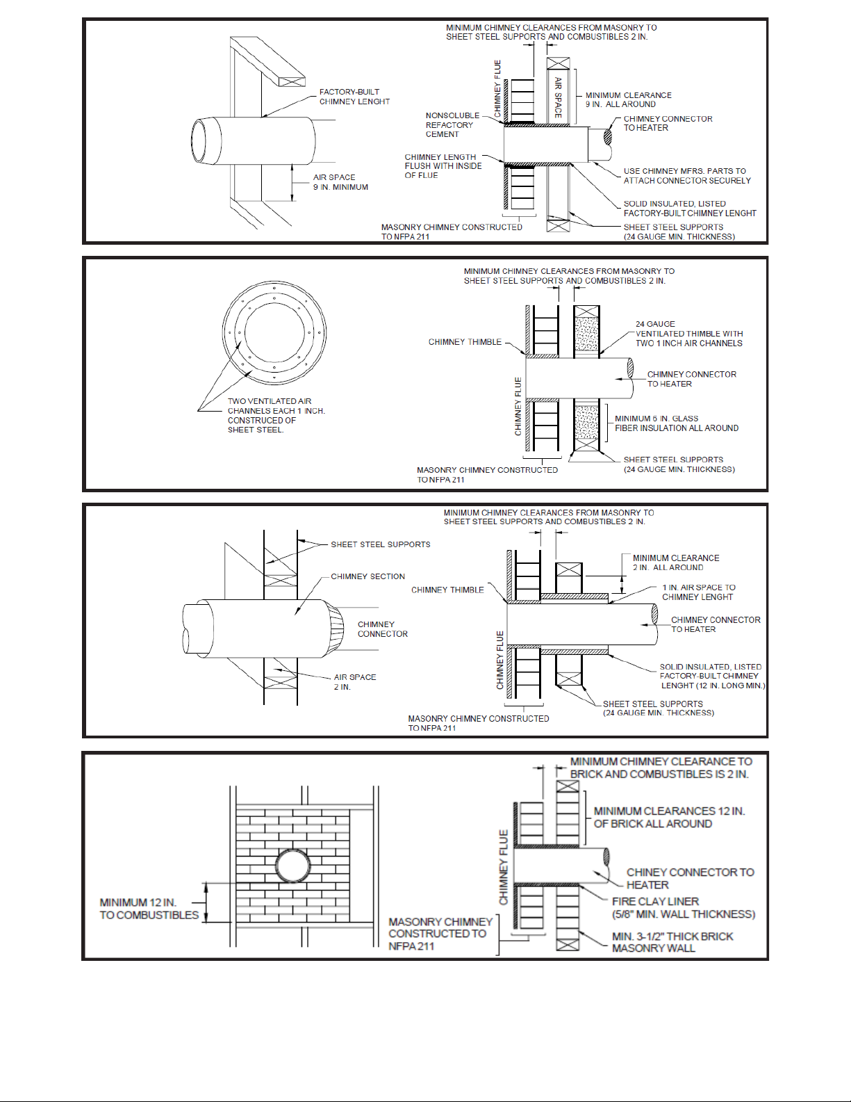
Rules For Connecting To A Masonry Chimney
1. Use a minimum of 3-1/2" inch brick masonry wall framed to a combustible wall. A fireclay liner
(ASTM 13 or equivalent) having a /8" inch minimum wall thickness must be used and it must
be at least 12" inches (1' foot) away from any material that could catch fire. The inside diameter
of the fire clay liner shall be sized for the proper snug fit to a 6" inch diameter chimney
connector pipe. The fireclay liner shall run to, but not beyond, the inner surface of the chimney
flue and be firmly cemented in place.
2. Use a solid insulated listed factory built chimney length having an inside diameter of 6" inches
and having 1" inch or more of solid insulation. There must be at least a 9" inch air space
between the outer wall of the chimney length and any combustible materials. The inner end of
the chimney length shall be flush with the inside of the masonry chimney flue which shall be
sealed to the flue and to the brick masonry penetration with non water-soluble refractory
cement. Flash sheet steel supports which are at least 24 gauge (0.02 " inches) in thickness shall
be securely fastened to wall surfaces on all sides. Fasteners between supports and the chimney
length shall not penetrate the chimney liner.
3. Use a 10" inch diameter ventilated thimble made of at least 24 gauge (0.02 " inch) steel having
two (2) 1" inch air channels. The ventilated thimble must be separated from combustible
materials by at least 6" inches of glass fiber insulation. The opening in the combustible wall
shall be covered and the thimble supported with sheet steel supports which are at least 24 gauge
(0.02 " inch) in thickness. The sheet steel supports shall be securely fastened to wall surfaces
on all sides and shall be sized to fit and hold the chimney section. Fasteners used to secure
chimney sections shall not penetrate the chimney flue liner.
4. Use an 8" inch diameter solid insulated listed factory-built chimney length which has 1" inch or
more solid insulation. The minimum length of the chimney section shall be 12" inches and will
serve a pass through for the 6" inch diameter chimney connector. There must be at least a 12"
inch air space between the outer wall and the chimney section and any combustible materials.
The chimney section shall be concentric with and spaced 1" inch away from the chimney
connector by means of sheet steel support plates on both ends of the chimney section. The
opening in the combustible wall shall be covered and the chimney section supported on both
sides with sheet metal supports which are at least 24 gauge (0.02 " inches) in thickness. The
sheet steel supports shall be securely fastened to wall surfaces on all sides and shall be sized to
fit and hold the chimney section. Features used to secure chimney sections shall not penetrate
chimney flue liner.
. A UL or NRTL listed factory-built wall pass-through system may be purchased and installed
according to the instruction supplied with it to provide a safe method of passing the chimney
connector through a combustible wall for connection to a masonry chimney.
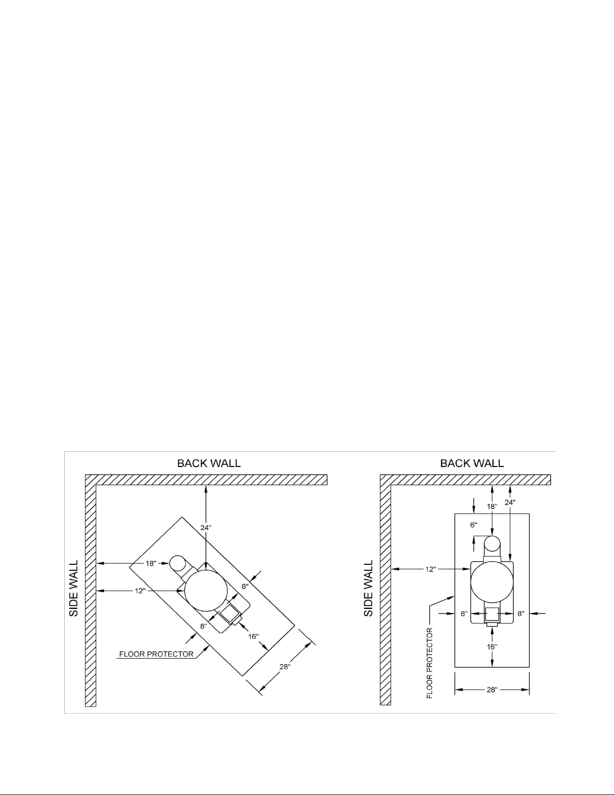
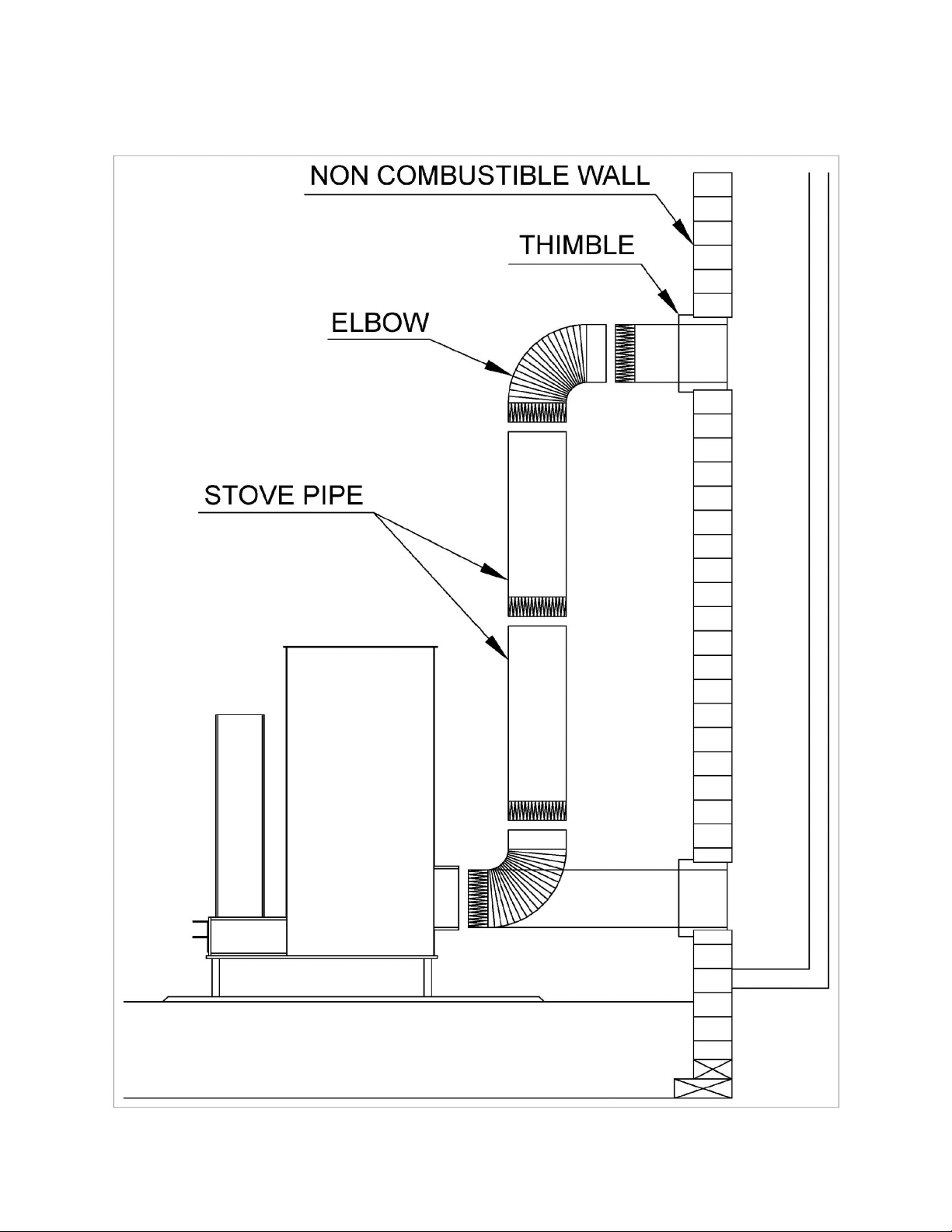
Please See the Following Pages for Diagrammatic Details
and Clearances for Masonry Chimney Installation
Page 7

Flue Connection Through a Non-Combustible Wall
Page 8

Page 9

Page 10

NRTL Listed Class A) Chimney
Carefully follow the chimney manufacturers instructions. Use only listed type HT per UL 103, 6"
inch diameter black or blued chimney connector with a minimum thickness of no less than 24 gauge. If
your chimney starts at the ceiling you will need enough 6" inch pipe to reach the ceiling. The top of the
chimney must be at least 3' feet above the roof and be at least 2' feet higher than any point of the roof
within 10' feet.
Rules For Connector Pipe Installation
1. Crimped end of the pipe must always be installed towards the heater. The pipe should slide into
the flue collar. The pipe should fit firmly inside and be mechanically attached to the flue collar,
locked with at least three (3) screws and sealed with furnace cement
2. If you have a pipe running horizontally, the horizontal length can not exceed 12' feet regardless
of the height of the chimney. If the chimney is 24' feet or less in height, the height of the
chimney must be at least twice the length of the horizontal run.
3. You must have at least 18" inches of clearance between any horizontal piping and the ceiling.
4. Secure any connector pipe joint with at least three (3) sheet metal screws and seal with furnace
cement, including the joint(s) at the chimney.
. It is recommended that not more than four (4) bends of 90 degrees OR any amount of bends
regardless of direction exceeding a total of 360 degrees be used in the pipe installation as more
than that can cause a decrease in draw and may cause back draft or smoke spillage.
6. The chimney connector shall not pass through an attic, roof space, floor, wall ceiling, or any
other similar concealed space. Where passage through a wall or partition of combustible is
desired, the installation must conform with NFPA 211.
*It is highly recommend that an insulated double wall pipe is used instead of a triple wall pipe.
Though a triple wall pipe can and has been used successfully, in situations where the pipe is exposed
outside the structure for long rises (such as a through wall installation) triple wall pipe does not have
nearly as effective of a draft as insulated double wall pipe. Triple wall pipe does not insulate the
chimney, instead it works via convection of cold air to cool the pipe. Due to the Rocket Heaters low
exhaust gas temperatures the cooling effect of triple wall pipes design prevents proper draft from being
established in some installations.
Please Go to the Next Page for Diagrammatic Details
and Clearances for NRTL Listed Class A Chimney Installation
Page 11

Through Ceiling Installation
Page 12

Installation Of Combustion Air Inlet
The Rocket Heater has a 4" combustion air inlet on each side of the fuel feed tube. If the heater
is to be installed in a mobile home a combustion air inlet (commonly/alternatively referred to as a
"fresh air intake" or "outside air intake") the heater must draw its combustion air from outside the
structure via the combustion air inlet. If the heater is being installed in a structure other than a mobile
home you can but are not required to install a combustion air inlet. It is recommended that a
combustion air inlet be installed as doing so increases the heaters efficiency.
Rules For Installation of Combustion Air Inlet
1. Only one combustion air inlet is used at any given time. The other combustion air inlet
must be capped off by inserting a crimped metal pipe cap and secured via sheet metal
screws through the two screw holes.
2. When installing the combustion air inlet duct/pipework it is recommended to keep the
pipe horizontal with as few bends as possible.
3. If you do use elbow(s), the sum of the angles of intake ductwork bends should not
exceed 180 degrees. It is always recommended to keep the bends as gradual as practical.
For example: two 4 degree angles are better than a 90 degree angle. No angles at all is
almost always preferable.
4. All duct/pipe connections are to be secured with three sheet metal screws at the joints
spaced approximately 120 degree's from each other. The only exception is where the
intake pipe connects to the combustion air inlet collar. The collar has 2 holes spaced 180
degree's from each other. Secure the pipe to the collar using 2 sheet metal screws
through those respective holes.
. Never use flexible pipe such as dryer vent hose/pipe including (but not limited to)
flexible pipes with a reflective/metallic appearance. Only rigid steel pipe is suitable for
the air inlet.
Page 13

Integration of Rocket Heater to Thermal Mass
The Liberator RMH-2.0 can be integrated to thermal mass. The benefits of using thermal mass
is a thermal battery/flywheel effect which allows the stove to keep the structure warm without
necessitating a continuous 24/7 firing. However, there are many variations of thermal mass integration
and each installation is almost inherently a custom designed and built to the customers needs. It is
highly recommended that an experienced mason, masonry heater, and rocket mass heater builder be
contacted for individual assessment and assistance.
Rules For Integration of Rocket Heater to Thermal Mass
1. Do not encase the burn chamber of the RMH-2.0 with thermal mass.
2. When routing an exhaust pipe horizontally through thermal mass the horizontal section
of pipe should have a rise going upwards towards the chimney of at least 3 degrees.
3. All clearances to combustibles guidelines must be adhered to. Thermal mass will not
insulate, shield, or protect combustibles from the stove or exhaust pipe.
4. The floor must be capable of supporting the heavy thermal mass bench. A slab
foundation is recommended. Contact a civil engineer if the thermal mass is NOT going
to be installed on a slab and reinforce the floor as necessary.
. The heat exchanging pipe should be at least 6” beneath any surface of the thermal mass.
6. The thermal mass must be made exclusively of non-combustible and non-flammable
materials.
7. Do not use corrugated pipe. Keep bends to a minimum. You will still need to install the
heater to a chimney as recommended in this manual. Use black stove pipe at least 24
gauge thick, secure by at least 3 screws at the joints. Do NOT route an exhaust vent
directly out of the wall. You need a chimney for a proper draft! Use one of the chimney
types described in pages 6-11 of this manual.
8. You can use a combustion air inlet when integrating the heater to thermal mass. In fact,
we recommend it as it will increase the heater's efficiency.
9. The horizontal length running through the thermal mass can not exceed 12' feet
regardless of the height of the chimney. If the chimney is 24' feet or less in height, the
height of the chimney must be at least twice the length of the horizontal run.
10.Thermal mass can partially encase the RMH-2.0 directly in addition to encasing the
horizontal run of pipe. However, do NOT cover the cooktop, ash cleanout door,
combustion chamber, or the top lid/fuel feed tube with thermal mass.
11.It is highly recommended that you be mindful of cleaning out the heat exchanging pipes
and the chimney. Install T-connectors at convenient locations to give yourself access to
the inside of the heat exchanging pipes of the thermal mass. Only use elbows in areas
where a T-connector would not give you any added accessibility.
It is highly recommended that you consult experienced professionals in the construction of a
true Rocket Mass Heater. Integrating a rocket heater to thermal mass is inherently a custom job that
requires utmost care, consideration, knowledge, experience, and talent to design, construct, and
operate. Though every installation and integration to thermal mass is by definition different and unique,
on the next page are some diagrams of some examples of basic installation layouts.
If you decide to integrate thermal mass to the Rocket Heater, RMH-2.0 we highly recommend
“The Rocket Mass Heater Builders Guide” by Ernie and Erica Wisner, ISBN: 086 718237 and
contacting experienced masonry heater and rocket mass heater builders.
Page 14

DIAGRAMMATIC DETAILS FOR THERMAL MASS
Page 15

Installation Of Flue/Chimney Damper
1. To install the flue damper, select one of the assembled sections of pipe (1) and measure its
length. Make a mark (2) halfway down the length of the section at a point 90 degrees away from
the section seam (3). Make a second mark (4) directly opposite the first mark (2) on the other
side of the stack section (1). Drill (or punch) a ¼-inch hole at each mark. After drilling the two
holes, insert the flue damper ( ) inside the modified section (6) and align the holes passing
through the flue damper with the holes drilled in the side of the stack section.
2. Thread the flue damper shaft (7) through the holes, locking the curved shank (8) of the flue
damper shaft (7) into the center slot (9) of the flue damper. When properly locked together, the
flue damper and operating handle (10) will be parallel.
How To Use A Flue/Chimney Damper
A flue damper must be used responsibly and with caution. When lighting/starting the heater make sure to open
the flue damper entirely for maximum draft. When the operating handle (10) is parallel with the vertical rise of
the chimney, that is the open position. When it is perpendicular, it is closed. Be sure to first let the heater warm
up to its maximum temperature and flow for at least 30 minutes. Then slowly and over a period of at least 10
minutes start to damper the stove. Dampering the stove slowly prevents backdrafting. When using fuel pellets,
make sure the damper is open for the last 30 minutes of run time
Page 16

Final Draft Inspection
Do NOT do this while the appliance is in operation)
To check if your chimney is drafting correctly, open the lighting/cleanout door and put a lit
match or cigarette lighter in front of the burn chamber. Then do the same (with the door closed) on top
of the fuel feeding area. If the flame is being pulled into the stove it is regarded as safe. If there is no
change in the flames direction, the draft is neutral. If the flame is being pushed away, the draft is
negative. If the draft is neutral or negative, then you must reinstall the heater with less horizontal run. If
you don't have a horizontal run, please call us (the manufacturer) or an expert for further advice.
Operation Of Your Rocket Heater On Wood
This multifuel appliance is not in any way similar to ordinary wood or pellet stoves and their
operation. The engineering principles in this appliance are vastly different than almost every
wood/pellet stove before it. Because of this, operation is quite abnormal for most people and can take
time to become accustomed to its use.
Note that this heater has paint that is not cured upon arrival. When lighting for the first time, do
it either outside or in a well ventilated area. Do not breathe the fumes given off.
It is recommended that you gather all the materials necessary to light the heater before you start
it. The materials you will need to start this heater are as follows: a lighter or match, three oblong cigar
shaped wads of paper, black and white newsprint, or equivalent whose width does not block air
flow/passage, at least two handfuls of very small twigs not more than 1/8" inch in width, larger twigs
about 1/4" to 1/2" inch wide, and running fuel not more than 1-1/2" inches in width.
To light the rocket heater, first lift open and off the lighting and cleanout door. Inspect for any
ashes from the last burn and clean out if ashes are present. Be sure that all paper wads are of an oblong
cigar-like shape to prevent a blockage of airflow. Place the first wad of paper inside the burn chamber
far enough from the front opening that it will not cause a fire but close enough that you can light it with
your lighter or match. Once the paper is starting to catch fire, use the cleaning tool provided and push
the wad all the way to the rear of the fire chamber. This will start a draft in the internal chimney.
Immediately close the lighting door, making sure that no ashes or debris are preventing complete
closure. Insert a second wad of unlit (not on fire) paper down the vertical fuel tube. Immediately drop
your handful(s) of small twigs on top of the unlit paper. Place a third wad on top and light it. The
topmost wad of paper should be burning downward, which should catch the twigs and paper
underneath. Once the twigs start to catch, place the medium fuel into the fuel tube. Once the medium
fuel has lit, follow this up with your full size fuel that you will burn for general heating.
Congratulations! You are now using a rocket heater. Be sure that you check the fire about every hour
and place more wood in as necessary. When finished using, place the lid on the top of the fuel feed
tube. This will prevent cold air from coming in and/or hot air from leaving the house, this step will
reduce the fuel consumption and run time necessary to maintain the comfortable temperature in the
building.
Page 17

Operation Of Your Rocket Heater On Fuel Pellets
The Pellet Hopper Adapter allows the Liberator RMH-2 to burn pellets without permanently
modifying the heater in any way.
Steps to Attach the Pellet Hopper Adapter
1. Install the Pellet Feed Tube on to the Pellet Hopper Adapter by inserting the tube into the
Coupler located on the bottom of the hopper.
2. Tighten the set screw (size /16" X 18 TPI) with the provided allen wrench.
3. Place the Pellet Hopper on top of the fuel feed tube of the Rocket Heater. Make sure that the
hopper is well seated and centered, and ensure that the pellet hoppers retainers (see next page)
are properly set within the tube. Make sure that the hopper always has the lid flip up from the
front with the hinge facing towards the back of the heater.
4. Open the ash cleanout door and insert the burn grate until the edge of the metal is within the
tube just enough to allow the ash cleanout door to close again, ideally as close to making
contact with the ash cleanout door as possible. Check and ensure that the Ash Cleanout Door
can be fully closed. Close the door.
Page 18

Steps to Start the Heater on Pellets
1. Fill the hopper with pellets, then open the Ash Cleanout Door.
2. Use a propane torch to ignite the pellets. Make sure that the torch's flame is making contact with
the fuel pellets and use a left to right sweeping motion across the bottom of the burn grate for
approximately 2 to 30 seconds or until there is a steady draft.
3. Turn off the torch and place it well away from the heater. Leave the Ash Cleanout Door off for
about 1 minute. Then close the ash cleanout door. The stove is now burning pellets.
Shutoff Valve illustrated directly below
Note that there is a Shutoff Valve provided with the Pellet Hopper. This allows you to stop the
flow of pellets down the pellet feed tube. The heater will run out of pellets in approximately 30
minutes to an hour from the time you push in the Shutoff Valve.
Page 19

NEVER load fuel from the front door (the one that slides up and down). This door is only for
lighting/startup and cleaning. Only load fuel from the top of the vertical tube. Specifically for the event
of an emergency or chimney fire, keep a five gallon bucket of sand handy to pour into the fuel chamber.
This will limit available oxygen to the chimney fire. Always have a fire extinguisher close by and at the
ready. Remember, if the situation at hand could cause personal injury by attempting to close off the air
supply, do not attempt to close the air supply, extinguish, or fight the fire. In such situations, evacuate
the building, call 911, and let professional firefighters handle the situation. REMEMBER that your
safety and the safety of others are of utmost concern and safety is the number one priority in any
dangerous situation. Your well being and safety of others nearby in these circumstances should be the
only determining factor for any actions to be taken. For more information and advice on fire safety,
safety precautions, and what to do in an emergency contact your local fire department and/or the
National Fire Protection Association (NFPA).
Page 20
Table of contents
Other Liberator Heater manuals
Popular Heater manuals by other brands

Accurex
Accurex XDG Installation, operation and maintenance manual

Kogan
Kogan SMARTERHOME KASTHFP2KWA user guide

Morris
Morris MHR-20044S user manual

PINK
PINK Triple Roll-on Heater Professional Edition quick start guide

Pro-Elec
Pro-Elec PELL0216 quick start guide

Euromatic
Euromatic Euro 15 Installation and servicing instructions