Licht-Technik Motoryoke BigBee MB-D1 Operating and installation instructions

Motoryoke BigBee
MB-D1
Software version 4.56
Functional description
Fabrication and marketin
Licht-Technik Vertriebs GmbH
Ha enbach & Grill
Osterwaldstr. 9-10 80805 München
Tel. 089-360528-0 Fax 089-360528-30
Last updated on: 15/10/19 Rev.: 1.06
Motoryoke MB D1 V4.56 Rev 1.06 1

Caution! Operate the device only after havin read and understood
operatin instructions (pa e 4)!
2 Motoryoke MB D1 V4.56 Rev 1.06

Table of content
Safety- and operatin instructions........................................................................................ 4
Quick start uide.................................................................................................................. 8
Identification....................................................................................................................... 14
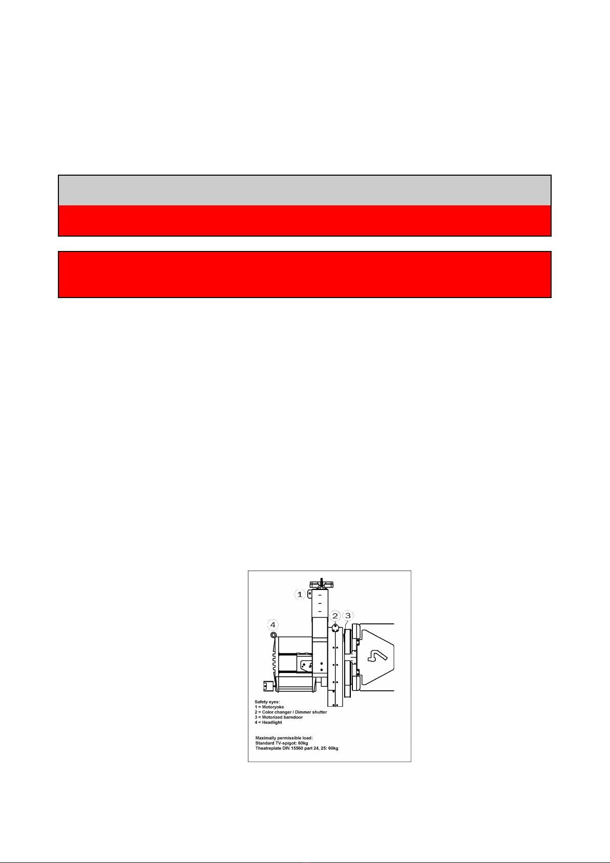
The Licht-Technik Motoryoke............................................................................................. 14
The DMX-standard in li htin ............................................................................................. 15
Cablin ............................................................................................................................... 16
Gettin started.................................................................................................................... 19
PAN – axis movin ran e................................................................................................... 20
User interface..................................................................................................................... 24
Display li htin ON/OFF..................................................................................................... 24
DMX channels motoryoke.................................................................................................. 25
P01 DMX-Address motoryoke............................................................................................ 26
P02 Focus unit ON/OFF..................................................................................................... 27
P03 Focus unit auto adjust (0% and 100%)....................................................................... 28
P05 PAN-axis middle position............................................................................................ 29
P06 TILT-axis 0-position..................................................................................................... 30
P11 PAN-axis movin ran e............................................................................................... 31
P12 TILT-down (ne ative) movin ran e............................................................................ 32
P13 TILT-up (positive) movin ran e.................................................................................. 33
P14 Focus unit 0%-value adjustment................................................................................. 34
P15 Focus unit 100%-value adjustment............................................................................. 35
P27 Speed PAN/TILT setup............................................................................................... 36
P30 Displayin the DMX-value........................................................................................... 37
P32 Selectin the user lan ua e....................................................................................... 38
P35 Unit number Netspider................................................................................................ 39
P36 Interchan in PAN movin direction........................................................................... 40
P37 Interchan in TILT movin direction........................................................................... 41
P38 Interchan in Focus movin direction........................................................................ 42
Technical data.................................................................................................................... 43
Readjustment of motoryoke axis........................................................................................ 44
Factory presettin s............................................................................................................. 45
Maintenance....................................................................................................................... 46
Error messa es.................................................................................................................. 48
Malfunctions....................................................................................................................... 49
Warranty............................................................................................................................. 50
Further information............................................................................................................. 50
EC Declaration of Conformity............................................................................................. 51
FCC Declaration of Conformity.......................................................................................... 52
Motoryoke MB D1 V4.56 Rev 1.06 3

Safety- and operating instructions
Before opening the housing disconnect the device from the mains !!!
Do not try in any case to touch the electronic throu h openin s, also with any objects.
This can cause an electrical accident that can lead to death!
Please note: The switching or risin /fallin from one input volta e ran e to another
durin operation can lead to dama e of the device!
When usin a generator, first start the enerator and wait for stable mains supply
volta e! After that switch on the power supply
When usin a enerator, leave the device switched off until the mains volta e and
frequency of the enerator is stable. Startin the enerator with switched on device will
dama e the device!!!
The motoryokes are tested by the erman trade association (Berufsgenossenschaft). The
devices conform with BGV C 1 and correspond to the newest safety re ulations.
Never exceed the maximal possible load of the mounting point. (Ri etc.)
Make sure that the maximum load of the fastenin spi ot will not be exceeded.
Never exceed the maximum load of the motoryoke. It is written on the identification plate.
The Motoryoke must only be operated in the operating position provided for this
purpose. Operatin position is vertically han in down, fastenin spi ot on the top or
vertically standin , spi ot on bottom.
Make sure that all fixtures of the yoke are tightened. Observe the torque of the screws or
nuts.
Fast the headli ht and all accessories like color chan er, dimmer shutter and barndoor
with safety belts. See picture:
4 Motoryoke MB D1 V4.56 Rev 1.06

Make sure that the safety belts have the ri ht diameter. For wei hts up to 60 k a belt of
10mm diameter is necessary for the one way method and a belt of 6mm is necessary for
the two way method.
The user is responsible for the correct use of safety parts!
Make sure that all parts which are mounted on the headli ht are ri ht tightened.
Lever forces must not have an effect on the Motoryoke. This means that the installed
motoryoke must not be shifted or bended! It is also forbidden when fastenin spi ot is
opened.
Do not push, pull or
dra
That applies also to the transport. It is absolutely forbidden to han up the yoke on its
spi ot when transported!
If you want to use a transport carriage, it must be certified by Licht-Technik!
The fastenin spi ot must be checked visual once a year. The spi ot must be in ri ht
an el to the housin . This must be checked in front and side view. A protractor can be a
help.
Furthermore, the spigot itself and the surface of the yoke must not be deformed. Make
sure that the spi ot is not loose or unformal.
If the spi ot is visibly damaged or deformed the motoryoke must not be used anymore.
The device has to be sent to Licht-Technik.
Motoryoke MB D1 V4.56 Rev 1.06 5
90°
One way safety belt Two way safety belt

A safety device that was once loaded or is visibly dama ed must not be used anymore!
When workin on the motoryoke, it must be switched off or the power line must be
interrupted. Make sure that the Motoryoke cannot be moved by the control panel.
The operator must make sure that no person is in the swivellin ran e of the motoryoke.
Inform your coworker and collea ues that the motoryoke is behavin like a work robot.
When the position is chan ed at the control panel the device is tryin to move on this
position. There is the dan er of bein bruised and et fri htened.
Admissible ambient temperature: 0..45 de ree Celsius.
The motoryoke must not be lit directly by the lamp. Limit the ran e of rotation (TILT axle)
so that the headli ht does not shine on the motoryoke.
Check the whole swivellin ran e of the headli ht. The manufacturers of the lamps specify
minimum permissible distances to inflammable materials. Make sure that these
distances are attended in every position of the lamp.
The manufacturers of the lamps specify maximum inclination. HMI headli hts are not
allowed to operate with the i nition electronic on the top.
The motoryoke must be kept dry. In case of water condensation a waitin period of up to
2 hours is necessary until acclimatisation is reached.
If knobs for manual movin are mounted, they can only be used if the motoryoke is in
power off condition. If the device is switched on and the knobs are rotated manually the
motors and/or earboxes can be dama ed.
Make sure to mount the lamp in the wei ht balancin point. The motoryoke must only be
operated with balanced tilt, otherwise the motor and/or earbox can be dama ed.
Observe the ri ht cablin . The cable-loop must be wide enou h and the correct cable-
route must be observed. The cables with the safety belt are last fixed left beside the safety
hole of the motoryoke. The cable packa e is routed over the mountin brid e and under
the pipe of the ri :
Wron routed cables can lead to defective cables, because of the mechanic and thermic
influence!
Check the complete pan movin ran e before startin the equipment by turnin by hand!
Too short cable loops can block the pan axis!
6 Motoryoke MB D1 V4.56 Rev 1.06

Never use the standard DMX-IN and the special control IN at the same time. Only one can
be used!
When it has to be assumed that a safe operation is no lon er possible, the equipment
must be switched off immediately and be secured against unintended operation.
This is the case when
–the equipment shows visible dama es
–the equipment is no lon er functional
–parts of the equipment are loose or slackened
–connectin lines show visible dama es
ttention:
Before startin the equipment the user must check the usefulness of the device for its
intended use.
We reject every liability:
–Dama es and indirect dama es or every kind of costs, which result from the use of
Licht-Technik products.
–Any dama es which result from ne li ence, improper use and setup, wron settin into
operation and use, i norin of valid safety re ulations, unsuitable use, bad
maintenance of Licht-Technik products.
Motoryoke MB D1 V4.56 Rev 1.06 7

Quick start guide
Prior starting, observe the safety and operating instructions on page 4!!!
Follow the description step by step to mount the lamp and pro ram the yoke!
For cable connections, please refer to section cabling, page 16.
ssembling position:
First, the yoke must move to build-in position. The yoke can stand on the floor or han in a
ri . Connect power cable, but let it switched off. Push the UP button and switch on. This
is the indicator for the electronic, that a lamp will be mounted.
If you are usin the focus drive, connect it but do not mount it to the focus knob of the
lamp. No DMX-si nal is needed. At the moment NO lamp is necessary!
Press the UP button and power up the yoke.
Wait until “adjust” is indicated. Release the button.
The electronic moves the axes includin focus (if used
and connected) to the build-in position.
Wait until “ready” is shown.
The yoke is ready to mount the lamp.
Power off the yoke or switch it off
Mounting direction:
Front is the side with the Licht-Technik lo o. Back is the
side with the connectors.
Mount the lamp so that the li ht is in the front.
8 Motoryoke MB D1 V4.56 Rev 1.06

Mounting the lampholders (each side one):
connection system
Mount the lampholders with one screw
Ti hten the screw Ready mounted lampholders
Make sure that the original lampholder is about in middle position.
Check if the lamphead is nearly in weight balance!
ssembling the yoke:
Lift the yoke over the lamp. Better et help from
another person. Get the lockin pin ready.
Adjust the yoke in width
Motoryoke MB D1 V4.56 Rev 1.06 9
lampholder
Check position for
balance point!

Insert the lockin pin.
Ready mounted lamp
10 Motoryoke MB D1 V4.56 Rev 1.06

ssembling focus drive:
If the lamp has a mechanical focus position indicator, move the drive by hand to about
middle position.
If no mechanical focus position indicator is existin , count the windin s of the knob from
end to end. Divide this number by two and find the middle position this way.
Count the total windin s to find the
approximate middle position. Adjust the drive
by hand to this encountered position
Mount the focus drive adapter
Close the retainers
Motoryoke MB D1 V4.56 Rev 1.06 11

Mount the motorbox. Insert the bolt
Focus spindle connection
Use the holding system to fix the motorbox on
the lamp
Ready mounted focus
Power on the yoke! (No button pushed!)
12 Motoryoke MB D1 V4.56 Rev 1.06

Programming and adjusting the 0% and 100% focus position:
Use P03 (detailed description on pa e 28) for automatic adjustment of this two positions:
Press MENU, select P03 with the UP and/or
DOWN key.
When P03 is indicated press MENU a ain
to ain access.
Press MENU a ain to start the adjustment move
The focus drive moves now from 0% position to 100% position to find the endstops.
The device is now ready for operation.
Set the pan middle position mechanically and rou hly of pan axis like illustrated on pa e
21.
Pro ram the pan middle position exactly at the display, refer to programming the middle
position on pa e 29
Pro ram the moving range of the P N-axle with P11. Refer to PAN-axle moving range,
pa e 0.
We recommend that the tilt programmings should not be chan ed by the user. It is
much more difficult than the pan axis and harder to understand. Better use and never
chan e the factory settin s. With that you can move the lamp on tilt a little bit to the top
and 90° to the bottom.
Motoryoke MB D1 V4.56 Rev 1.06 13

Identification
The motoryokes are identified by a number on the identification plate as follows:
MB – XX
MB = Motoryoke. On every motoryoke identification plate.
XX = ST: Type: Studio yoke
R: Type: tube yoke
SH: Type: Show yoke
D1: Type: Flexible in width
The Licht-Technik Motoryoke
The motorised yoke of Licht-Technik is a versatile, precise and powerful device for
headli ht positionin .
Since 1991 the company Licht-Technik desi ns motoryokes for film, TV and theatre
houses. We only use the best components of the world-wide leadin companies. The
aluminium housin s are characterised by hi h stability, hi h quality and low dead wei ht.
The devices are manufactured on own CNC controlled machines and can uarantee a
continuously high quality standard. Noise is optimised sequentially. We manufacture the
Motoryokes in cooperation with our customers.
The control is made by the DMX-512 USITT-interface. The rou h and fine positionin and
the speed for each main-axis (PAN/TILT) can be controlled. As an option a focus unit
and/or a motorized barndoor can be controlled by DMX.
The Motoryokes can be offered with the followin options :
Focus unit:
With the focus unit the headli ht-focus can be driven by DMX. The positionin takes
place in 256 steps (1 DMX channel). The speed is fixed. Therefore no DMX-channel for
speed has to be set.
Rotation unit:
With the rotation unit the headli ht can be rotated by DMX. The positionin takes place
in 256 steps (1 DMX channel). The speed is fixed. Therefore no DMX-channel for
speed has to be set.
The built in 32-Bit Processor provides a hi h throu hput of the computer, quick
positionin and uncomplicated handlin . Even when tri erin several motoryokes the
precise control system provides a hi h synchrony of the movement.
Because of the absolute value device, the motoryoke does not perform any initialisation
runs after power up.
14 Motoryoke MB D1 V4.56 Rev 1.06

The li hted LCD display (the li ht can be switched off) leads the user in plain text
instructions throu h the various pro rammin steps. The instructions are available either
in en lish or erman lan ua e.
The motoryoke has a mechanical and electronical torque delimitation on the PAN and
TILT axle. The mechanical torque limitation is realised with a friction clutch and prevents
a personal injury of people workin on the yoke. Furthermore the drives and earboxes
will not be dama ed when movin the yoke in case of power off.
The electronical torque delimitation switches off the motors in case of blockin (e. .
blockin because of movin onto a wall or decoration). The display shows an appropriate
error messa e.
The controlling of the two main axles (PAN and TILT) is done with 2 DMX-channels per
axle. With only one channel (8-Bit) a resolution of 256 steps could be realised. With two
channels (16-Bit) a resolution of 65536 steps is possible. The first channels of each axle
represents the rou h position information (at 360° ran e of rotation about 1.4 de rees per
step). The second channel represents the fine position information. The speed of the
motoryoke is determined with one channel (PAN and TILT to ether) or with two channels
(PAN and TILT separated).
The DMX-standard in lighting
Because of many problems with analogue data-si nals from the control panels to the
dimmers the DMX-standard was developed in 1990. DMX only needs two wires to control
up to 512 dimmers di itally. On the other hand, the old analo ue method needs one wire
for every dimmer. Many kilometers of cable have been saved.
The DMX-si nal is based on the industrial RS485 interface. It is desi ned for maximum
len ths up to 1200m. Normally this len th is under condition in theatre or studio not
possible (stron electrical fields because of the HMI lamps). As a result of internal tests
we recommend a maximum len th of 200m (only DMX line, 5pin). On every DMX
transmitter a maximum of 32 DMX receiver can be connected. All devices must be
connected in a row (cablin from A to B, from B to C, from C to D etc.). The last device in
such a row must be terminated with a resistor (470 Ohm). If more than 32 devices should
be connected a booster or splitbox must be inserted.
A splitbox is a device with one DMX input and several DMX outputs. The si nal is
refreshed. Thus it is possible to use different DMX lines.
The reliability of data transmission was increased because of usin DMX. One of the
reatest advanta es is universally usefulness. Now devices from different manufacturers
can be controlled by every control panel.
Motoryoke MB D1 V4.56 Rev 1.06 15

Cabling
Caution!
Please read the operatin and safety instructions on pa e 4 (continuin ) before cablin !
Make sure that the motoryoke is switched off before cablin !
For pinout of cables refer to technical data, page 43.
Connectors top:
Never use the standard DMX-IN and the special control IN at the same
time. Only one can be used!
16 Motoryoke MB D1 V4.56 Rev 1.06
Mains switch
Mains IN
Standard DMX IN
Special control IN
for vision control
and LT-Pilot
Control si nal OUT
connection for
further stirrups

Cabling:
(1)Maximum 4 units if Vision Control or LT-Pilot is used!
DMX addressing and unit button assignment
If you are usin a standard DMX desk please refer to the DMX channel layout described
on pa e 25!
If the Vision Control or the LT-Pilot is used the followin addresses must used and
parameters must be set:
The followin menus must be pro rammed (please refer to the correspondin manuals):
Motorized yoke: P01 = DMX address see above
P02 = 1 Focus/Rotation module on (if used and connected)
P03 = 0 Motorized barndoor off
P27 = 1 Speed channels for pan and tilt seperately
P38 = 0 Focus movin direction = normal.
Dimmer Shutter: P01 = DMX address see above
P15 = 3 Sin le channel mode
Motoryoke MB D1 V4.56 Rev 1.06 17
OR!
Mains IN
LT-Pilot receiver
OR!
Vision control (cabled)
Standard
DMX-desk LT-Pilot (wireless control)
Mains IN
Connection to next
stirrup (note 1)
DMX cable 5pin
DataPower
cable 4pin
Unit 1 Unit 2 Unit 3 Unit 4
DMX first address stirrup 1 21 31 41
DMX address Dimmer Shutter (optionally) 8 9 10 11

Connectors bottom:
Caution!!
Make lar e enou h loop at the data- and lamp cable. Make sure that there is enou h
space in cablin over the entire movin ran e of the yoke. The cables must neither be
stretched nor bended!
The cables are fixed with cable fixers. The clips are mounted on the back side of the yoke.
It is possible to connect a Licht-Technik color chan er and/or a dimmer-shutter.
18 Motoryoke MB D1 V4.56 Rev 1.06
DMX DataPower 4pin
Focus only!
Shutter
Color chan er
etc.

Getting started
Assemble the lamp like illustrated in quick setup guide on pa e 8.
Setup the motoryoke on the desired place according to the operating and safety
instructions, page 4.
Mount Focus unit if used. Refer to Quick start guide, page 8.
Set the middle position mechanically and rou hly of pan axis like illustrated on pa e 21.
Cable the motoryoke like illustrated in cabling, page 16.
Switch on the motoryoke. After testin its internal pro ram memory and the control it
shows the overall operatin hours. Now the motoryoke is movin to the pro rammed
position. The second display line shows the DMX-address and value of the PAN-axle.
Caution!
Make sure that the motoryoke is not moved by the control panel before pro rammin .
Otherwise the motoryoke will move durin pro rammin if the position is chan ed at the
panel!
If the focus unit is used pro ram P0 Focus unit on/off, pa e 27 to 1. If not pro ram it to 0.
Pro ram the middle position exactly at the display via P05, refer to programming the
middle position on pa e 29.
Pro ram the moving range of the P N-axle. Refer to P11, PAN-axle moving range, page
31.
Normally not necessary, but possible is the pro rammin of the TILT moving range. Refer
to TILT-axle moving range, pa e .
If you are usin a control desk with joystick, vision control or LT-Pilot the speed channel
setup in P27, pa e 36, must be pro rammed to 1!
If you are usin a standard DMX desk P27 can be pro rammed to 1 or 0. Decide for
yourself how you want to control the speed.
Further programming possibilities like DMX addressin are specified on the followin
pa es.
Tip:
When the motoryoke is in programming mode, all movin orders are i nored. Make sure
that the device is in operatin mode after pro rammin , otherwise it will not move! Press
two times the OK key for leavin the pro rammin mode!
Motoryoke MB D1 V4.56 Rev 1.06 19

P N – axis moving range
Basically:
The PAN-axle is the axle which moves the lamp horizontally.
The moving range of the main axles can be adapted individually. For the PAN-axle are
two parameters required. The middle position and an angle in which the motoryoke
should move. If an an le of 90 de rees is pro rammed, the motoryoke moves from its
middle position 90° to the left and 90° to the ri ht. The whole movin ran e is 180°.
If an an le of 45° is pro rammed, the yoke will move 45° to the left and right. The movin
ran e is 90°.
This setup is useful when the motoryoke is han in in a corner for example.
20 Motoryoke MB D1 V4.56 Rev 1.06
Front
0° = middle position
90° -90°
1 0°
Front
0° = middle position
45° -45°
90°
Table of contents
Other Licht-Technik Lighting Equipment manuals
Popular Lighting Equipment manuals by other brands

Vision & Control
Vision & Control LDLF30x420-B470/24V/-a Instructions for use

Klus
Klus OBIT W4826 Mounting instructions

Intermatic
Intermatic EL200 Series Installation and user instructions

Diamante
Diamante GLOWLINE HO 600 user manual

LED World
LED World FA36M57-2M-12V-X Important instructions

Stella
Stella PRO reflex user manual