Licht-Technik Motoryoke YipMan Quick guide

Motoryoke YipMan
MB-DY V1
Software version 4.58
Functional description
Fabrication and arketing
Licht-Technik Vertriebs G bH
Hagenbach & Grill
Osterwaldstr. 9-10 80805 München
Tel. 089-360528-0 Fax 089-360528-30
Last updated on: 31/07/2020 Rev.: 1.00
Motoryoke YipMan1 V4.58 Rev 1.00 1

Caution! Operate the device only after having read and understood
operating instructions
Please read first the
operating and safety instructions
on page 6
2 Motoryoke YipMan1 V4.58 Rev 1.00

Inhaltsverzeichnis
Introduction........................................................................................................................... 4
Appropriate use.................................................................................................................... 4
The Licht-Technik otoryoke YipMan.................................................................................. 4
Safety- and operating instructions........................................................................................ 6
Quick start guide.................................................................................................................. 9
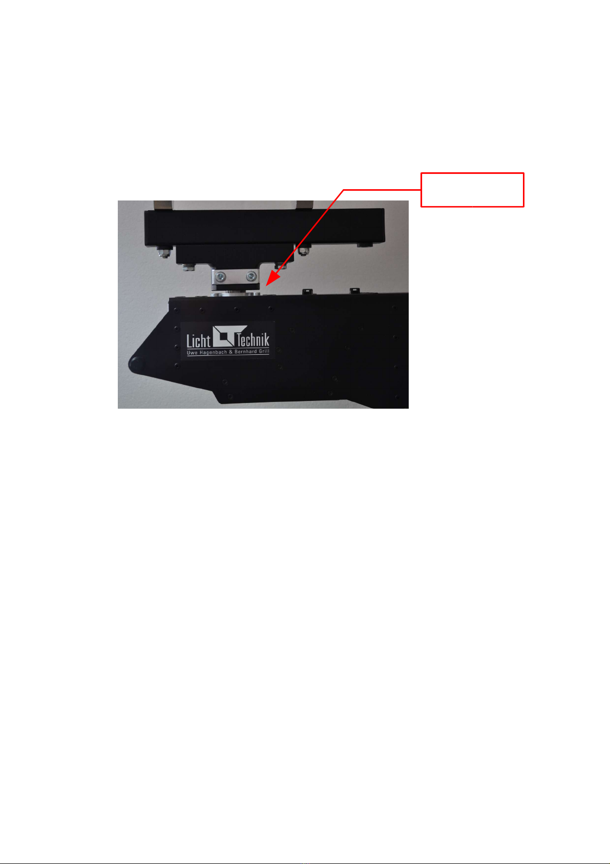
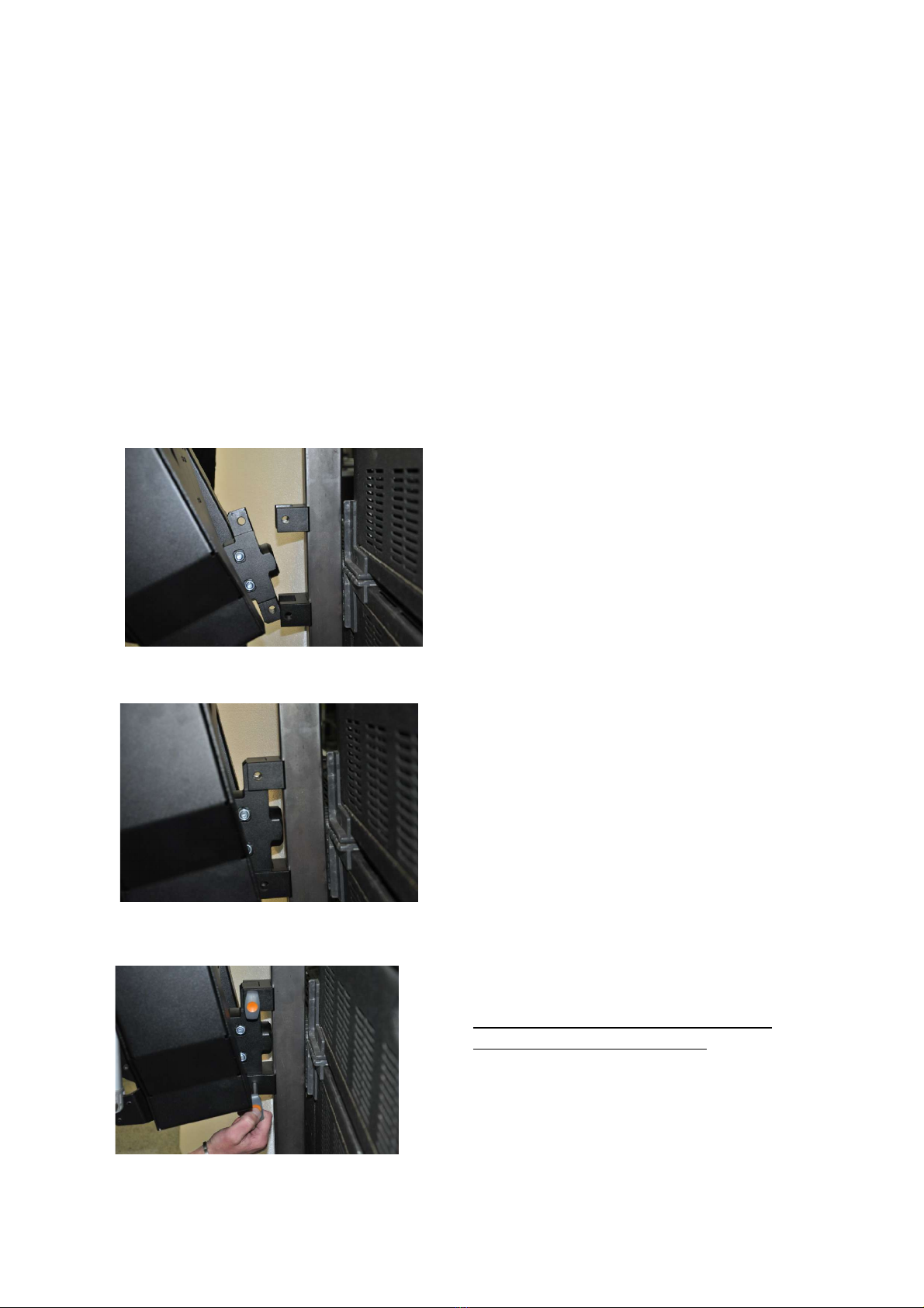
Asse bling the oving device........................................................................................... 10
Identification....................................................................................................................... 11
The DMX-standard in lighting............................................................................................. 11
Cabling............................................................................................................................... 12
Getting started.................................................................................................................... 14
PAN – axis oving range................................................................................................... 15
User interface..................................................................................................................... 18
Display lighting ON/OFF..................................................................................................... 18
DMX channels otoryoke.................................................................................................. 19
P01 DMX-Address otoryoke............................................................................................ 20
P02 Rotation unit ON/OFF................................................................................................. 21
P05 PAN-axis iddle position............................................................................................ 22
P06 TILT-axis 0-degree position......................................................................................... 23
P11 PAN-axis oving range............................................................................................... 24
P12 TILT-down (negative) oving range............................................................................ 25
P13 TILT-up (positive) oving range.................................................................................. 26
P14 Focus / rotation 0%-value........................................................................................... 27
P15 Focus/rotation unit 100%-value adjust ent................................................................ 28
P27 Speed PAN/TILT setup............................................................................................... 29
P30 Displaying the DMX-value........................................................................................... 30
P32 Selecting the user language....................................................................................... 31
P33 PAN-axis loading position........................................................................................... 32
P34 TILT-axis loading position............................................................................................ 33
P35 rotation-axis loading position...................................................................................... 34
P36 Interchanging PAN oving direction........................................................................... 35
P37 Interchanging TILT oving direction........................................................................... 36
P38 Interchanging rotation oving direction...................................................................... 37
Technical data.................................................................................................................... 38
Werkseinstellungen............................................................................................................ 39
Maintenance....................................................................................................................... 40
Error essages.................................................................................................................. 42
Malfunctions....................................................................................................................... 43
Warranty............................................................................................................................. 44
Further infor ation............................................................................................................. 44
EC Declaration of Confor ity............................................................................................. 45
Motoryoke YipMan1 V4.58 Rev 1.00 3

Introduction
Dear custo er,
we gratefully thank you for purchasing our product!
You acquired a product which is state of the art and eets all require ents of the national
and european standards. The confor ity is proofed.
To ensure this state and a safe operation, you have to obverse this anual and especially
the operating and saftey instructions.
Appropriate use
The otoryoke was designed to ove a headlight, speaker, bea er or so ething like
that.
The outdoor use is li ited, because the housing is spray water proof but not co pletely
sealed.
The contact to water should be avoided.
The use of cleaning fluids should be avoided, this could lead to da ages.
For cleaning use a dry, lintfree towel or rag.
The co plete product ust not be odified and opened.
The safety and operating instructions ust be observed.
The Licht-Technik motoryoke YipMan
With the Licht-Technik otoized yoke, we can offer an flexible, versatile, precise, durable
and reliable device for positioning of different devices.
Co pany Licht-Technik developes otoryokes since 1991 for fil , TV an theatre lighting.
Only high quality parts fro leading anufacturers are used.
The alu iniu housing supports high stability and quality with a low dead load.
The devices are anufactured with odern CNC achines. Therefore we can keep a
constant high quality level.
The noise is opti ized steadily to support an extre e quiet positioning.
We anufacture and develop the yokes in close cooperation with our custo ers to eet
their wishes and require ents.
The control is realized by the DMX- 12 USITT-interface. The rough and fine positioning
(16-Bit, two channels) and the speed for each ain-axis (PAN/TILT) can be controlled. In
addition, we can support a rotation function with one DMX-channel
The built in 32-Bit Processor provides a high throughput of the co puter, quick
positioning and unco plicated handling. Even when triggering several otoryokes the
precise control syste provides a high synchrony of the ove ent.
4 Motoryoke YipMan1 V4.58 Rev 1.00

Because of the absolute value device, the otoryoke does not perfor any initialisation
runs after power up. In addition a power down does not affect the current position, also
because of the self-locking gearboxes.
The lighted LCD display (the light can be switched off) leads the user in plain text
instructions through the various progra ing steps. The instructions are available either
in english or ger an language.
The otoryoke has a echanical and electronical torque delimitation on the PAN and
rotation axle. The echanical torque li itation is realised with a friction clutch and
prevents a personal injury of people working on the yoke. Further ore the drives and
gearboxes will not be da aged (except Tilt-axle) when oving the yoke in case of power
off.
The electronical torque delimitation switches off the otors in case of blocking (e.g.
blocking because of oving onto a wall or decoration). The display shows an appropriate
error essage.
The controlling of the two ain axles (PAN and TILT) is done with 2 DMX-channels per
axle. With only one channel (8-Bit) a resolution of 256 steps could be realised. With two
channels (16-Bit) a resolution of 6 36 steps is possible. The first channels of each axle
represents the rough position infor ation (at 360° range of rotation about 1.4 degrees per
step). The second channel represents the fine position infor ation. The speed of the
otoryoke is deter ined with one channel (PAN and TILT together) or with two channels
(PAN and TILT separated).
Motoryoke YipMan1 V4.58 Rev 1.00 5

Safety- and operating instructions
Danger to life!
Before opening the housing disconnect the device from the mains !!!
Do not try in any case to touch the electronic through openings, also with any objects.
This can cause an electrical accident that can lead to death!
Please note: The switching or rising/falling fro one input voltage range to another
during operation can lead to da age of the device!
When using a generator, first start the generator and wait for stable ains supply
voltage! After that switch on the power supply
When using a generator, leave the device switched off until the ains voltage and
frequency of the generator is stable. Starting the generator with switched on device will
da age the device!!!
The otoryokes are tested by the ger an trade association (Berufsgenossenschaft). The
devices confor with BGV C 1 and correspond to the newest safety regulations.
Never exceed the axi al possible load of the mounting point. (Rigg etc.)
Make sure that the maximum load of the fastening spigot will not be exceeded.
Never exceed the maximum load of the otoryoke. It is written on the identification plate
and in the technical data section, page .
The Motoryoke ust only be operated in the operating position provided for this
purpose. Operating position is vertically hanging down, fastening spigot on the top.
Make sure that all fixtures of the yoke are tightened. Observe the torque of the screws or
nuts.
Fast the headlight and all accessories like color changer, di er shutter and barndoor
with safety belts.
The user is responsible for the correct use of safety parts!
Make sure that all parts which are ounted on the headlight or oving devic are right
tightened.
Lever forces ust not have an effect on the Motoryoke. This eans that the installed
otoryoke ust not be shifted or bended! It is also forbidden when fastening spigot is
opened.
6 Motoryoke YipMan1 V4.58 Rev 1.00

That applies also to the transport. It is absolutely forbidden to hang up the yoke on its
spigot when transported!
If you want to use a transport carriage, it ust be certified by Licht-Technik!
The fastening spigot ust be checked visual once a year. The spigot ust be in right
angel to the housing. This ust be checked in front and side view. A protractor can be a
help.
Further ore, the spigot itself and the surface of the yoke ust not be defor ed. Make
sure that the spigot is not loose or unfor al.
If the spigot is visibly damaged or defor ed the otoryoke ust not be used any ore.
The device has to be sent to Licht-Technik.
A safety device that was once loaded or is visibly da aged must not be used any ore.
When working on the otoryoke, it ust be switched off or the power line ust be
interrupted. Make sure that the Motoryoke cannot be oved by the control panel.
The operator ust ake sure that no person is in the swivelling range of the otoryoke.
Infor your coworker and colleagues that the otoryoke is behaving like a work robot.
When the position is changed at the control panel the device is trying to ove on this
position. There is the danger of being bruised and get frightened.
Ad issible a bient temperature: 0..45 degree Celsius.
The otoryoke ust not be lit directly by a ounted la p. Li it the range of rotation
(TILT axle) so that the headlight does not shine on the otoryoke.
Check the whole swivelling range of the headlight. The anufacturers of the la ps specify
minimum permissible distances to infla able aterials. Make sure that these
distances are attended in every position of the la p.
The anufacturers of the la ps specify axi u inclination. HMI headlights are not
allowed to operate with the ignition electronic on the top.
Motoryoke YipMan1 V4.58 Rev 1.00 7
90 degree

The otoryoke ust be kept dry. In case of water condensation a waiting period of up to
2 hours is necessary until accli atisation is reached.
If knobs for anual oving are ounted, they can only be used if the otoryoke is in
power off condition. If the device is switched on and the knobs are rotated anually the
otors and/or gearboxes can be da aged.
Make sure to ount the payload in the weight balancing point. The otoryoke ust only
be operated with balanced tilt, otherwise the otor and/or gearbox can be da aged.
Observe the right cabling. The cable-loop ust be wide enough and the correct cable-
route ust be observed. The cables with the safety belt are last fixed left beside the safety
hole of the otoryoke.
Wrong routed cables can lead to defective cables, because of the echanic and ther ic
influence!
Check the co plete pan moving range before starting the equip ent by turning by hand!
Too short cable loops can block the pan axis!
Never use the standard DMX-IN and the special control IN at the same ti e. Only one
can be used!
When it has to be assu ed that a safe operation is no longer possible, the equip ent
ust be switched off i ediately and be secured against unintended operation.
This is the case when
–the equip ent shows visible da ages
–the equip ent is no longer functional
–parts of the equip ent are loose or slackened
–connecting lines show visible da ages
Attention:
Before starting the equip ent the user ust check the usefulness of the device for its
intended use.
We reject every liability:
–Da ages and indirect da ages or every kind of costs, which result fro the use of
Licht-Technik products.
–Any da ages which result fro negligence, i proper use and setup, wrong setting into
operation and use, ignoring of valid safety regulations, unsuitable use, bad
aintenance of Licht-Technik products.
8 Motoryoke YipMan1 V4.58 Rev 1.00

Quick start guide
Prior starting, observe the safety and operating instructions on page 6!!!
Follow the description step by step to ount the la p and progra the yoke!
For cable connections, please refer to section cabling, page
Assembling position:
First, the yoke ust ove to build-in position. The yoke ust hang in a rigg. Connect
power cable, but let it switched off. Push the UP button and switch on. This is the indicator
for the electronic, that a la p will be ounted.
No DMX-signal is needed. At the o ent NO la p or oving device is necessary!
Press the UP button and power up the yoke.
Wait until “adjust” is indicated. Release the button.
The electronic oves the axes including focus (if used
and connected) to the build-in position.
Wait until “ready” is shown.
The yoke is ready to ount the la p.
Power off the yoke or switch it off
Motoryoke YipMan1 V4.58 Rev 1.00 9

Assembling the moving device
Cabling and connecting possibilities are described on page 12
Start with mains in only!
Do not connect the DMX line!
Power on the otoryoke
Use the quick start guide on page 9.
When all axles have been oved to loading position, asse ble the payload:
1. Move the connection together
2. Connect it
3. Lock the connection with the ball lock pins:
The ball lock pins can be opened by
depressing the orange area!
10 Motoryoke YipMan1 V4.58 Rev 1.00

Identification
The otoryokes are identified by a nu ber on the identification plate as follows:
MB – XX
MB = Motoryoke. On every otoryoke identification plate.
XX = ST: Type: Studio yoke
R: Type: tube yoke
SH: Type: Show yoke
D1: Type: Flexible in width
DY: Type: One point connection (YipMan)
The DMX-standard in lighting
Because of any proble s with analogue data-signals fro the control panels to the
di ers the DMX-standard was developed in 1990. DMX only needs two wires to control
up to 512 di ers digitally. On the other hand, the old analogue ethod needs one wire
for every di er. Many kilo eters of cable have been saved.
The DMX-signal is based on the industrial RS48 interface. It is designed for axi u
lengths up to 1200 . Nor ally this length is under condition in theatre or studio not
possible (strong electrical fields because of the HMI la ps). As a result of internal tests
we reco end a axi u length of 200m (only DMX line, 5pin). On every DMX
trans itter a axi u of 32 DMX receiver can be connected. All devices ust be
connected in a row (cabling fro A to B, fro B to C, fro C to D etc.). The last device in
such a row ust be ter inated with a resistor (470 Oh ). If ore than 32 devices should
be connected a booster or splitbox ust be inserted.
A splitbox is a device with one DMX input and several DMX outputs. The signal is
refreshed. Thus it is possible to use different DMX lines.
The reliability of data trans ission was increased because of using DMX. One of the
greatest advantages is universally usefulness. Now devices fro different anufacturers
can be controlled by every control panel.
Motoryoke YipMan1 V4.58 Rev 1.00 11

Cabling
Caution!
Please read the operating and safety instructions on page 6 (continuing) before cabling!
Make sure that the otoryoke is switched off before cabling!
Caution!
Make sure that the cables run in wide loop to the otoryoke. Check, if the cables are long
enough for the co plete oving range. The cables ust not be stretched or bended in
any case!
Connection possibilities:
Never use the inputs at the same time together!
Only one of the control-IN can be used!
12 Motoryoke YipMan1 V4.58 Rev 1.00
Mains IN
Neutrik PowerCon
DMX512 IN
VisionControl
IN
DMX512 OUT
Power switch

A maximum of four units can controlled via Vision Control or LT-Pilot!
If you use a standard DMX-desk, please observe the DMX-footprint on page 19
If you use the Vision-Control or the LT-Pilot re ote control syste , please use the
following channels and progra ing values:
DMX-addressing and unit assignment:
The following parameters ust be progra ed possibly. (Please observe the
corresponding anuals).
Motorized yoke: P01 = DMX address, see above
P02 = 1 Rotation unit on (if used)
P27 = 1 Speed channels for pan and tilt seperately
P38 = 0 Rotation direction = nor al.
Di er Shutter: P01 = DMX address, see above
P15 = 3 Single channel ode
Motoryoke YipMan1 V4.58 Rev 1.00 13
Unit 1 Unit 2 Unit 3 Unit 4
DMX start address motoryoke 1 21 31 41
DMX address dimmer shutter (optional) 8 9 10 11
8 9 10 11DMX address focus unit (optional) Control
via Dimmer-Shutter function

Getting started
Mount the otoryoke syste at the desired place with observing the operating and safety
instructions on page 6!
Mount the oving device like described in Assembling the device on page 10.
Cable the syste like described on page 12.
Switch on the otoryoke. After testing its internal progra e ory and the control it
shows the overall operating hours. Now the otoryoke is oving to the progra ed
position. The second display line shows the DMX-address and value of the PAN-axle.
Caution!
Make sure that the otoryoke is not oved by the control panel before progra ing.
Otherwise the otoryoke will ove during progra ing if the position is changed at the
panel!
Progra the middle position exactly at the display via P05, refer to programming the
middle position on page 22.
Progra the moving range of the PAN-axle. Refer to P11, PAN-axle moving range, page
2 .
Nor ally not necessary, but possible is the progra ing of the TILT moving range. Refer
to TILT-axle moving range, page .
If you are using a control desk with joystick, vision control or LT-Pilot the speed channel
setup in P27, page 29, ust be progra ed to 1!
If you are using a standard DMX desk P27 can be progra ed to 1 or 0. Decide for
yourself how you want to control the speed.
Further programming possibilities like DMX addressing are specified on the following
pages.
Tip:
When the otoryoke is in programming mode, all oving orders are ignored. Make sure
that the device is in operating ode after progra ing, otherwise it will not ove! Press
two ti es the OK key for leaving the progra ing ode!
14 Motoryoke YipMan1 V4.58 Rev 1.00

PAN – axis moving range
Basically:
The PAN-axle is the axle which oves the la p horizontally.
The moving range of the ain axles can be adapted individually. For the PAN-axle are
two para eters required. The middle position and an angle in which the otoryoke
should ove. If an angle of 90 degrees is progra ed, the otoryoke oves fro its
iddle position 90° to the left and 90° to the right. The whole oving range is 180°.
If an angle of 45° is progra ed, the yoke will ove 45° to the left and right. The oving
range is 90°.
This setup is useful when the otoryoke is hanging in a corner for exa ple.
Motoryoke YipMan1 V4.58 Rev 1.00 15
front
0° = Middle position
90° -90°
180°
front
0° = Middle position
45° -45°
90°

Setting the PAN middle position:
The iddle position nor ally is the position in which the installed device is used most.
It can be set at enu P05, PAN-axis middle position, page 22.
You should start with the pan axis in the current adjusted iddle position. If you do not
know if this is the case, power up the device and set the DMX-channel for position to 50%.
Do not forget to set the speed value to 100%. Channels are 1 (position) and 5 (speed) at
factory presettings.
The moving angle can be set in enu P11, PAN-axle moving range, page 2 . It can be in
a range within 10 and 160°. Reco ended is 90°.
Caution !!
Check the entire moving range of the la p:
The la p- anufacturer specify minimum distances to infla able aterials. Never fall
below the ini u distance in no position of the la p!
Make sure that no cable will be broken, bended, stretched or damaged anyhow by
reason of turning the otoryoke!
16 Motoryoke YipMan1 V4.58 Rev 1.00

TILT – axis moving range
Basically:
The TILT-axle is the axle which oves the la p vertically.
Nor ally the factory presettings are suitable and nothing ust be set. The la p can be
oved fro vertically down to a few degrees on the top.
The 0-degree position represents the vertical position of the ounting socket. Fro this
position a positive oving range and a negative oving range is defined. The positive
range is uch s aller than the negative range. This is the reason why it can not be
deter ined where the 50% DMX position is.
TILT oving range is in opposite to the PAN oving range asy etric. It is set in two
enus. (P12, page 25 and P13 page 26).
Do not forget to press two ti es the OK key to get back to working level after
progra ing.
Check the co plete new oving range with the DMX-signal.
Caution !!
Check the entire moving range of the la p:
The la p- anufacturer specify minimum distances to infla able aterials. Never fall
below the ini u distance in no position of the la p!
Check that the motoryoke will not be illu inated when la p is on top position.
Make sure that no cable will be broken, bended, stretched or damaged anyhow by
reason of turning the otoryoke!
Headlights generally ust not be operated with the ignition electronic on the top. Observe
the specifications of the la p anufacturer!
Motoryoke YipMan1 V4.58 Rev 1.00 17
+20°
0°- position
-90°
TILT-plus moving r nge
TILT-minus moving r nge
Tot l moving r nge

User interface
In nor al operating ode the LCD-display indicates different infor ation. The first line
shows the Licht-Technik oving text with details on type of device, software version and
telephone nu ber. The second line indicates the first DMX-address and its inco ing value
(8-Bit, 0..255). For the otoryoke, this address is the PAN-address.
With the four keys the device can be progra ed. Instruction for this, is on the following
pages.
Display lighting ON/OFF
In nor al operation ode the LCD backlight is switched off to avoid a disturbing light.
Only if an error occurs or during progra ing the light will be switched on auto atically.
The user can also switch it on anually to see what is indicated.
Condition: Motoryoke is on working level
Operation:
depress. Display lighting ON
depress again. Display lighting OFF
18 Motoryoke YipMan1 V4.58 Rev 1.00
1. DMX- ddress V lue of the 1. DMX- ddress
Moving text with type of device, softw re-version nd telephone number
UP key
DOWN key MENU key
OK key

DMX channels motoryoke
The following chapters require the DMX-channel assignment of the otoryoke. Please
note the difference which is progra ed in P27, PAN/TILT DMX speed channel setup,
page 29. This enu deter ines if the speed is given by one or by two channels.
Therefore, the otoryoke requires between 5 (without optional co ponents) and 12 DMX-
channels.
If a Joystick, Vision-control or LT-Pilot is used, P27 (page 29) has to be set to 1. If a
standard-DMX desk is used both possibilities are possible. Choose the one you want but
keep the channel layout in ind!
The first address (PAN rough) is set in enu P01, DMX-address motoryoke, page 20. All
other addresses follow after this first address according to this table.
Examples:
1. Motoryoke P27 = 1 (like right colu n in table). The next free DMX-channel would be
nu ber 8. For use of an fan-focus for expa ple.
2. Motoryoke P27 = 0 (like left colu n in table). Next free channel would be channel 6.
Please note!
Color changer, di er shutter and the co bined device „MagVader“ are controlled by
their own electronic. These devices are co pletely independent regarding the
electronical control!
Motoryoke YipMan1 V4.58 Rev 1.00 19
Channel Motoryoke (P27=0) Motoryoke (P27=1)
1 PAN roughly PAN roughly
2 PAN fine PAN fine
3 TILT roughly TILT roughly
4 TILT fine TILT fine
5PAN/TILT speed PAN speed
6 Focus- or Rotation (optional) TILT speed
7 Focus- or Rotation (optional)

P01 DMX-Address motoryoke
At this point the first DMX-address of the otoryoke can be adapted to the desired DMX-
address of the light ixing panel. This address represents the PAN-DMX-address. All
other addresses follow this address. Refer to DMX-channels motoryoke, page 19
Range of values: Address 1..512
Operation:
depress You are now on enu level. The last adjusted enu
point is displayed, e.g.:
Menu P02: rotation- odule on/off
depress ... until Menu P01 is displayed.
depress The second line displays the currently adjusted value.
depress Adjust the desired DMX address.
depress You are back on enu level.
depress The equip ent is ready for operation.
20 Motoryoke YipMan1 V4.58 Rev 1.00
Menü
Menü
Ok
Ok
This manual suits for next models
1
Table of contents
Other Licht-Technik Lighting Equipment manuals
Popular Lighting Equipment manuals by other brands

Govee
Govee H6199 user manual

MSD Ignition
MSD Ignition 89631 installation instructions

Kompernass
Kompernass KH 4145 operating instructions

Global Pool Products
Global Pool Products X2 BASKETBALL Assembly Installation Guide

blackburn
blackburn GRID SIDE LIGHT SET user manual

PRACHT
PRACHT BERNINA-LED Maintenance Instruction