Lierda LSD4WN-2332XGW1 User manual

第1页 共 20 页
IoT Interworking
Make Your Life Smart
Security Code
LSD4WN-2332XGW1 (Gateway)
User's Manual
File version: Rev02.1
Last updated on: Sept 18, 2019
Security Code

20
IoT Interworking
Make Your Life Smart
Security Code
Revision History
Product
name
Gateway
Product model
LSD4WN-2335XGW2
Prepared by
Wang Yankai
Date of preparation
20180820
No.
Change logs
Changed by
Audited
by
File
version
Date of change
1
Initial version
Wang Yankai
Rev01
2018-08-20
2
New bottom plate
change
Chen
Yongwei
Rev02
2019-05-23
3
Explanation for
Adding Replacement
Antenna
Chen
Yongwei
Rev02.1
Sept 18,
2019-09-18

20
IoT Interworking
Make Your Life Smart
Security Code
Contents
目录
Chapter 1 Overview.......................................................................................................................................... 4
1.1 Overview............................................................................................................................................................ 4
1.2 Accessories list................................................................................................................................................... 5
1.3 Interface description........................................................................................................................................... 6
Chapter 2 Installation.......................................................................................................................................7
2.1 Installation protection.........................................................................................................................................7
2.2 Unpacking inspection......................................................................................................................................... 7
2.3 Installation of necessary equipment................................................................................................................... 7
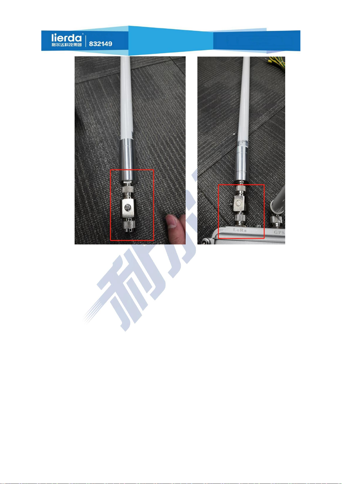
2.4 Antenna installation............................................................................................................................................8
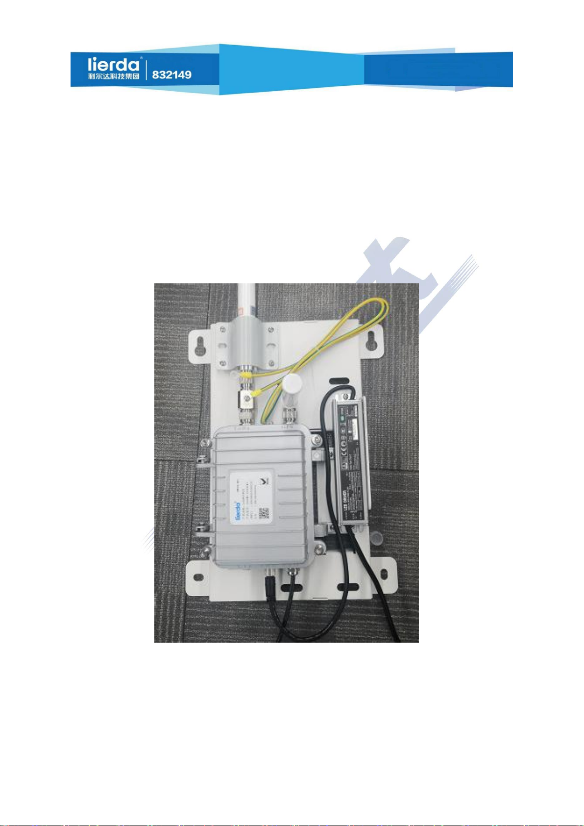
2.5 Gateway body installation................................................................................................................................ 10
2.6 Power supply installation................................................................................................................................. 12
2.7 Grounding cable installation............................................................................................................................ 13
2.8 Antenna extension scheme............................................................................................................................... 14
2.9 Interface waterproofing.................................................................................................................................... 15
2.10 Pole and wall mounting..................................................................................................................................15
2.12 Antenna replacement...................................................................................................................................... 17
Chapter 3 Broadcast Compliance Instructions..................................................................................... 18
Chapter 4 Precautions....................................................................................................................................18
Chapter 5 Troubleshooting..........................................................................................................................18

20
IoT Interworking
Make Your Life Smart
Security Code
Chapter 1 Overview
1.1 Overview
The Lierda LSD4WN-2332XGW1 (Gateway) is a TDD LoRaWAN IoT gateway that supports the
902-928MHz frequency range. The main body of the gateway is deployed in a wall-mounted manner,
and the antenna can be extended to a suitable location through the feeder. It is equipped with 12VDC
waterproof outdoor power supply.
Figure 1 Gateway as a whole

20
IoT Interworking
Make Your Life Smart
Security Code
1.2 Accessories list
No.
Device
Qty
Unit
Remarks
①
LoRa antenna
1
/
/
②
Gateway body
1
/
/
③
GPS antenna
1
/
/
/
⑤
Lightning arrester
1
/
/
⑥
Ground wire
1
/
/
⑦
Power supply
1
/
/
⑧
Gateway bracket
1
/
/
⑨
Antenna holder
1
/
/

20
IoT Interworking
Make Your Life Smart
Security Code
1.3 Interface description
Figure 2 Gateway interface
Place
○
1
○
2
○
3
○
4
○
5
○
6
Function
GPS ANT
LoRa ANT
ETH
PWR
LTE
/

20
IoT Interworking
Make Your Life Smart
Security Code
Chapter 2 Installation
2.1 Installation protection
The installation, operation and maintenance of the gateway must be performed by
professionally trained technicians.
The installation location of the gateway must be limited and not accessible to
non-maintenance personnel.
The surface of the gateway may become hot during normal operation, affecting the
surrounding environment.
All installation operations must comply with local and national electrical codes.
Do not operate the equipment during lightning.
The gateway runs continuously during the life cycle, and it is necessary to ensure that it is
grounded well and stably.
Install the grounding first, and remove grounding wire last at the time of dismantling.
It is forbidden to operate the gateway with power.
The power supply device of the gateway must include overcurrent protection function.
2.2 Unpacking inspection
Consider the following when unpacking a new gateway:
1. Check the shipping carton and check for damage.
2. Unpacking should be carried out in a clean and dry position possible.
3. Do not discard the shipping carton or foam inserts. If it needs to be repaired or reconfigured,
they needs to be used.
2.3 Installation of necessary equipment
The following tools are required during installation:
1. M4 hex screwdriver
2. flat-nose pliers (antenna interface locking)
3. Diagonal pliers

20
IoT Interworking
Make Your Life Smart
Security Code
4. Wire brush
5. Clean and dry cloth
6. Antioxidant compounds
7. Electric drill with a suitable drill bit (wall mounted)
2.4 Antenna installation
2.4.1 GPS antenna installation
Figure 3 GPS antenna installation
As shown in Figure 4, the GPS antenna corresponds to the RF interface of the position marked with
the GPS word on the gateway shell, aligned and tightened.
Note: GPS antenna vertical gateway facing outward
2.4.2 LoRa (omnidirectional fiberglass) antenna installation

20
IoT Interworking
Make Your Life Smart
Security Code
Figure 4 LoRa (omnidirectional fiberglass antenna) installation
(1). First install the lightning arrester at the antenna RF interface.
(2). Correspond the LoRa (omnidirectional fiberglass antenna) antenna and the lightning arrester to
the interface below the position marked with the LoRa word on the gateway shell, align and tighten.

20
IoT Interworking
Make Your Life Smart
Security Code
2.4.3 Antenna installation completion sketch map
Figure 5 Antenna installation completion display
Note: For the RF part of antenna connected to the inside of the gateway, its installation needs to
pay attention to the external lightning protection. An antenna feed arrester should be installed between
the LoRa antenna and the gateway, and the antenna must be installed within the protection area of the
lightning rod.
2.5 Gateway body installation

20
IoT Interworking
Make Your Life Smart
Security Code
Figure 6 Gateway body installation
As shown in the figure:
(1) Place the gateway on the bottom plate, align the screw holes on the side of the gateway (marked
with red box), and tighten the screws.
(2) Place the antenna holder above the lightning arrester, align the bottom plate screws (marked
with red box), and tighten the screws.
Note:

20
IoT Interworking
Make Your Life Smart
Security Code
1. The interface between the antenna and the gateway needs to be rotated and locked with a
flat-nose pliers, otherwise it may have a certain impact on the RF performance.
2. The direction of the GPS antenna needs to be perpendicular to the plane of the bottom plate of
the gateway, face outward and be parallel to the ground to ensure the quality of the GPS signal.
2.6 Power supply installation
Figure 7 Gateway power supply installation Figure 8 Gateway power cord installation
2.6.1 Power supply body installation
As shown in Figure 7:
Place the output socket end of the power supply upward (marked with yellow box), make it close to
the wall of the bottom plate (marked with green box), align the hole with the bottom plate screw hole
(marked with red box), and tighten the screws.
2.6.2 Power cord installation
As shown in Figure 8:
Align the notch of the power cord interface with the protruding part of the gateway power
connector (marked with red box), insert and tighten.

20
IoT Interworking
Make Your Life Smart
Security Code
Note:Products do not provide power,For reference only
2.7 Grounding cable installation
Figure 9 Grounding wire installation
The gateway is considered a permanently connected device and requires a permanently connected
protective earth (PEG) conductor. The ground connection of the protective earth is through a grounding
hole of an M6 on the shell, as shown in the figure above.
The gateway grounding system should follow local and national electrical codes. The protective
earth conductor of the grounding hole is mandatory. It must be the first one to be connected at the time
of grounding. The proper wiring and connection of this cable is the key to strong lightning resistance.
Connection inductance and ground resistance should be minimized.
The grounding cable installation steps are as follows:
1. Gently grind the surface of the antenna feeder lightning arrester with a fine steel wire brush to
remove the oxide layer.
2. Use a clean cloth to remove debris from the surface.

20
IoT Interworking
Make Your Life Smart
Security Code
3. Immediately coat the contact surface with a layer of antioxidant compound.
4. Use M6 screws, bolts, and washers to install the grounding cable to the antenna feeder through
the grounding hole.
5. Connect the other end of the grounding cable as described above.
2.8 Antenna extension scheme
Figure 10 Antenna extension cable installation
The LoRa antenna can be mounted to the desired position via an RF extension cable (optional
accessory) for a better signal coverage quality. When fixed, the antenna can be fixed to the wall or pole

20
IoT Interworking
Make Your Life Smart
Security Code
by the antenna bottom plate and the antenna semi-circular pressure plate, with the help of expansion
screws or U-shaped hoops, as shown in Figure 10.
Note:no external amplifier can be used.
2.9 Interface waterproofing
Figure 11 interface waterproofing installation
The N-type interface of the LoRa and GPS antennas is not waterproof, so it must be protected with
waterproof tape or waterproof cold-shrink tubes when used outdoors. It is recommended to use the
cold-shrink sleeve protection interface produced by Shenzhen COTRAN New Material Co., Ltd.
2.10 Pole and wall mounting

20
IoT Interworking
Make Your Life Smart
Security Code
2.11.1 Pole mounting
Figure 12 Pole hole
Pass the stainless steel cable tie through the bottom hole (marked with red box) in the red box as
shown in the figure and tighten it.

20
IoT Interworking
Make Your Life Smart
Security Code
2.11.2 Wall mounting
Figure 13 Wall mounting fixing hole
As shown in Figure 13, the expansion screws have been tightened up for the wall according to the
hole position of the bottom plate (marked with red box), following by fixing the gateway.
2.12 Antenna replacement
LoRa antenna replacement
Antenna must satisfy some conditions:
①Antenna transmission and reception must meet the frequency range: 902-928 MHz
②Antenna impedance: 50Ω
GPS antenna replacement
Antenna must satisfy some conditions:
①Antenna transmission and reception must meet the frequency range: 1560-1575MHz
②Antenna impedance: 50Ω
Note:Replacement step reference to 2.4 Antenna installation

20
IoT Interworking
Make Your Life Smart
Security Code
Chapter 3 Broadcast Compliance
Instructions
LSD4WN-2332XGW1 supports AS923, AU915, KR923 and other frequency bands. The maximum
output power of the gateway is 23dB±1dB. The transmission power is adjustable. Please follow the local
radio management regulations to limit the working power of the gateway.
Chapter 4 Precautions
1. It is strictly forbidden to power on the unconnected antenna. It is strictly forbidden to replace
and remove the antenna with power;
2. Before connecting the power, you must ensure that the connections are good;
3. The Ethernet connected to the gateway needs to obtain the IP automatically and can access the
public network.
4. The user should not replace the power adapter at will;
5. For outdoor installation, please take lightning and rain protection measures;
Chapter 5 Troubleshooting
1. The node is unable to communicate with the gateway normally:
Solution:
①Check if the power supply and network are normal;
②Whether the connected network cable can automatically obtain IP, and does
not bind the MAC address;
③Confirm that the node gateway works in the corresponding frequency table;
④Confirm that the server is normal;
⑤Confirm that the gateway has added a server and the parameters are the same
as the server;

20
IoT Interworking
Make Your Life Smart
Security Code
⑥Confirm that the node has added the server and the parameters are the same
as the server;

20
IoT Interworking
Make Your Life Smart
Security Code
Notice to Users
Welcome to use the products of Lierda Science & Technology Group Co., Ltd. Please read this
Notice before using our products; if you have started using our products, it means that you have read and
accepted this Notice.
Lierda Science & Technology Group Co., Ltd. reserves the right to interpret and modify all
materials provided which are subject to changes without notice.
Prepared by: Lierda Science & Technology Group Co., Ltd. Wireless Sensor Network
August 2018
Contact Information
Company Address: 1401, Building 1, Lierda Internet of Things Technology Park, No. 1326 Wenyi West
Road, Hangzhou
Tel: 18167172921
Mail box: xt@lierda.com
Official website: http://rf.lierda.com/
Table of contents
Popular Gateway manuals by other brands

BinTec
BinTec RS120 Reference manual

XLOCK
XLOCK 100 instruction manual

Avaya
Avaya IG550 Installing and configuring

Shenzhen Sailwider Electronics Co., Ltd.
Shenzhen Sailwider Electronics Co., Ltd. RCS-Z31C Product specification

ActionTec
ActionTec GT704WGB Specifications

Raisecom
Raisecom RC953-8FE16E1 user manual