Lifan 125GY-5 User manual

LF125GY-5改.p65 2012-3-1, 10:291

Operator and Passenger:
This motorcycle can carry an operator and one passenger. The maximum load weight of the motorcycle must not exceed 150kg.
Off-road
This motorcycle is designed for off-raod use.
Pay special attention to statements preceded by the following words:
WARNING: Indicates a strong possibility of severe personal injury or death if instructions are not followed.
CAUTION: Indicates a possibility of equipment damage if instructions are not followed.
NOTE: provides helpful information.
Environmental Protection (EP): indicates special precautions that must be taken to meet environment protection laws and regulations. Improper use of a
motorcycle may cause environment pollution.
Never take any actions on your motorcycle if it requires any repair, take it to a professional or an authorized service station, otherwise, you may take upon
yourself the consequences.
The manual should be considered as a permanent part of the motorcycle and should remain with the motorcycle when resold.
All rights reserved. Any reprinting or unauthorized use without our prior written permission is expressly prohibited.
Thank you for choosing LIFAN motorcycle. May you enjoy riding all time.
The manual contains the necessary instructions and guidance with respect to the operation and maintenance of the motorcycle, and BE SURE TO
READ IT CAREFULLY BEFOREYOU RIDE THE MOTORCYCLE. Proper operation and maintenance can guarantee a safe riding to minimize troubles
of the motorcycle and keep it in a sound condition, which can extend the engine service life.
All rights reserved. No part of this publication may be reproduced without our prior written permission.
IMPORTANT NOTICE
LF125GY-5改.p65 2012-3-1, 10:292

CONTENTS
Engine Oil (EP) .................................................................... 10
Clear away Carbon Deposit (EP) ........................................ 10
Spark Plug (EP) ................................................................... 10
Air Cleaner (EP) .................................................................. 10
Valve Clearance.................................................................... 11
Muffler (EP)........................................................................ 11
3-Way Catalytic Converter (Optional)(EP) ........................ 11
Fuel Filter (EP) .................................................................... 12
Operation of Throttle.......................................................... 12
Idle Speed of Carburetor (EP) ............................................ 12
Check Leaks along Air Supply (EP) .................................... 12
Clutch .................................................................................. 12
Drive Chain ......................................................................... 13
Front Brake ......................................................................... 13
Rear Brake ........................................................................... 14
Brake Light .......................................................................... 14
How to Use Brake Wear Indicator ......................................14
Front/Rear Shock Absorber and Suspension ....................... 14
Tyre ..................................................................................... 14
Front Wheel ......................................................................... 15
Rear Wheel .......................................................................... 15
Fuse ..................................................................................... 15
Battery (EP) ........................................................................ 15
TROUBLESHOOTING, STORAGEAND OPTIONALPARTS
Troubleshooting .................................................................. 17
Cleaning and Storage ............................................................ 17
Removal from Storage ......................................................... 17
Fall-Over Safety Device (Optional) .................................... 18
Anti-theft Device (Optional) .............................................. 18
ELECTRICDIAGRAM ........................................................... 19
SPECIFICATIONS ................................................................. 20
MOTORCYCLE SAFE RIDING
Safe Riding Rules ................................................................... 1
Protective Cloths ................................................................... 1
Refitting ................................................................................. 1
Loading .................................................................................. 1
Accessories ............................................................................ 1
GENERALINFORMATION
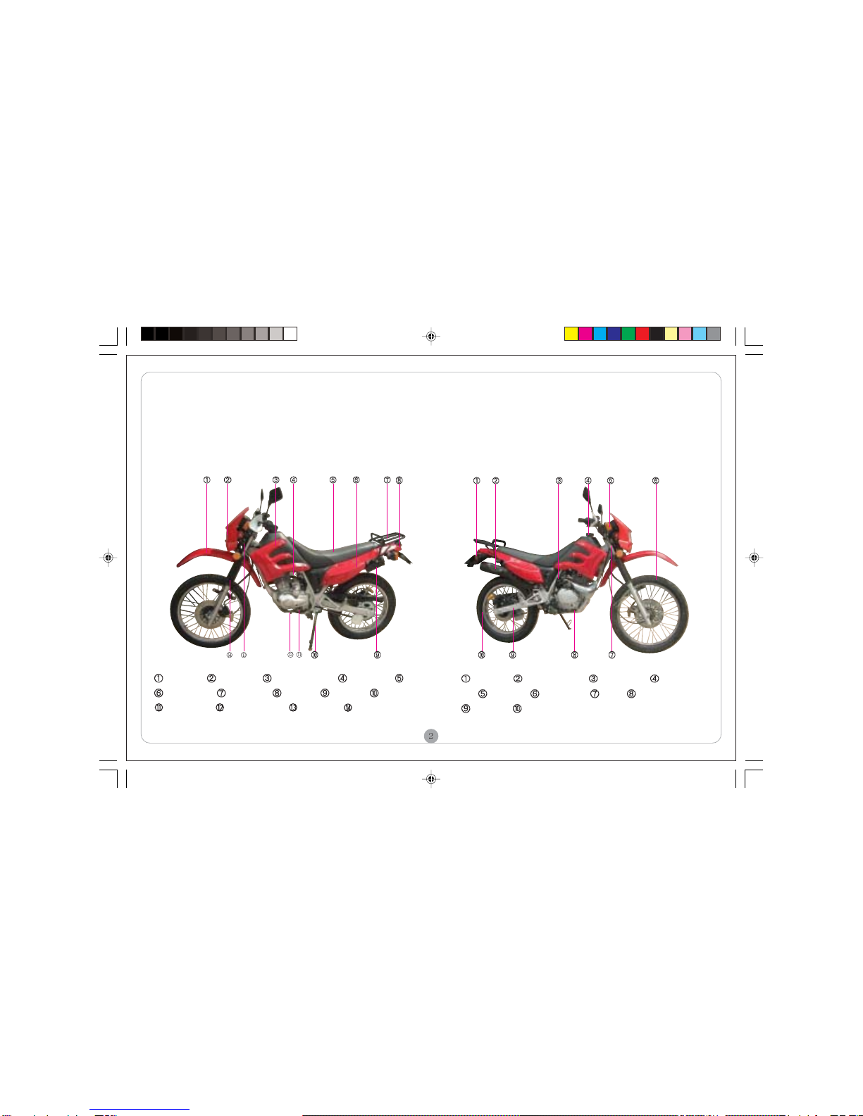
Parts Location ....................................................................... 2
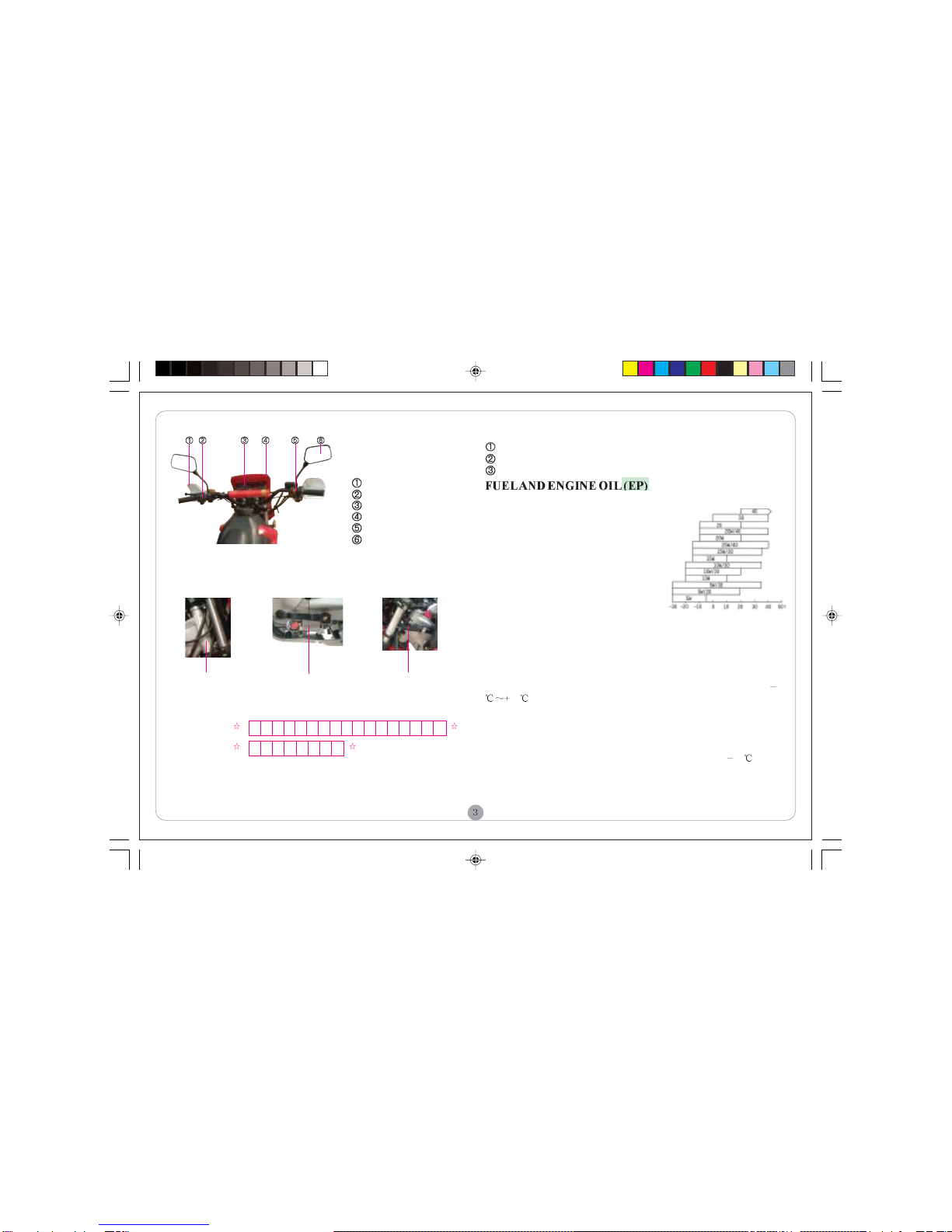
VIN Record ........................................................................... 3
Fuel and Engine Oil (EP) ....................................................... 3
CONTROLLING PARTS
Meter and Indicators ............................................................. 4
Ignition Switch and Steering Lock ......................................... 4
Right Handlebar Controls ...................................................... 4
Left Handlebar Controls........................................................ 5
Choke Lever .......................................................................... 5
Refueling and Cap ................................................................. 5
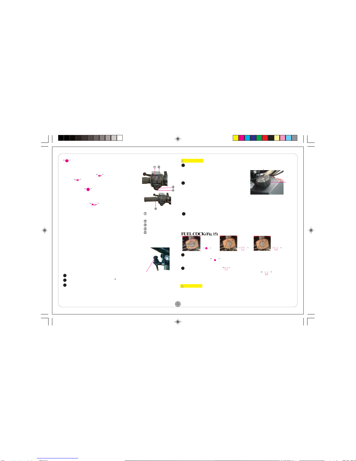
Fuel Cock .............................................................................. 5
Gearshift Pedal ...................................................................... 6
Rear Brake Pedal ................................................................... 6
Rear ShockAbsorber ............................................................. 6
Side Stand .............................................................................. 6
OPERATIONGUIDE
Pre-ride Inspection ................................................................ 7
Starting the Engine ................................................................. 7
Breaking-in ............................................................................ 7
Riding .................................................................................... 7
Braking and Parking ............................................................... 8
MAINTENANCE
Tool Kit ................................................................................. 9
Maintenance Schedule ........................................................... 9
LF125GY-5改.p65 2012-3-1, 10:293

MOTORCYCLE SAFE RIDING
SAFERIDINGRULES
WARNING Motorcycle riding requires special efforts on your part
to ensure safety. Know these requirements before you ride.
Always make a pre-ride inspection before you start the engine. You may
prevent accident or equipment damage.
Most countries require a special motorcycle riding test or license. Make
sure you are qualified before you ride. NEVER lend your motorcycle to an
inexperienced rider.
Make yourself conspicuous to help avoid the accident that wasn’t your
fault:
a) Wear bright or reflective clothing.
b) Don’t ride in another motorist’s “blind spot”.
c) Don’t speedily cross another’s way.
d) Obey all national and local laws and regulations.
e) Obey the speed limits, and NEVER travel faster than conditions warrant.
f) Signal before you make a turn or lane change to draw other motorists’
attention.
g) Use extra caution at intersections, parking lot entrances and exits.
h) Always remember to ride with both hands and keep both feet on the rider
footrest while the passenger grasps the handrail with both feet on the rear
footrest.
PROTECTIVECLOTHS
For the safety sake, always wear a helmet, a face shield, dust glasses and
protective clothing. Your passenger needs the same protection.
The exhaust system becomes hot during operation, and it remains hot for
a while after stopping the engine. Take care not to touch the exhaust
system while it is hot. Wear clothing that fully covers your legs.
Do not wear loose clothing that could catch on the control levers, wheels,
etc.
REFITTING
WARNING Arbitrarily refitting the motorcycle or removing the
original parts may make riding unsafe, and is illegal also. The user
must obey all national and local laws and regulations in relation to
vehicle and traffic. If you have a good proposal concerning refitting of
the motorcycle, please write us. The refitment can be done with per-
mission of the Co. Otherwise, the user will take the consequences.
LOADING
WARNING Addition of accessories and cargo may reduce the
motorcycle’s stability, performance and safe operating speed.
Keep cargo and accessory weight lower and close to the center of the
motorcycle. Load weight equally on both sides to minimize imbalance. As
weight is located further from the motorcycle’s center of gravity, handling
is proportionally affected.
Adjust tyre pressure and rear suspension to suit load weight and riding
conditions.
Make sure that cargo is fastened on the vehicle.
Do not attach items to the handlebars, fork or fender. Otherwise, unstable
handling or slow steering response may occur.
The maximum load weight of the motorcycle is 150kg. Please do not
overload.
ACCESSORIES
Genuine accessories of the Motors have been specifically designed and
tested on the motorcycle. Beacuse the factory cannot test all other accessories,
you are personally re-sponsible for selection, installation and use of acces-
sories not produced by the Co. Always follow Safe Riding Rules and these
below:
Carefully inspect the accessory to make sure that it does not obscure any
lights, reduce ground clearance or banking angle, or limit suspension travel,
steering travel or control operation.
Do not install other cooling equipment for the engine.
Do not add electrical equipment that will exceed the motorcycle’s electri-
cal system capacity.
LF125GY-5改.p65 2012-3-1, 10:294

Fig. 1 (Left view) Fig. 2 (Right view)
GENERAL INFORMATION
PARTSLOCATION(Fig. 1-3)
Fr. fender Headlight Tank trim cover Carburetor Seat
Side cover Rear carrier Taillight Tool box Side stand
Engine code Gearshift pedal Nameplate Fr. shock absorber
Rr. winker Exhaust muffler Kick-starter Fuel filler
cap Fr. winker Fr. wheel VIN Rr. brake pedal
Rr. fork Rr. wheel
LF125GY-5改.p65 2012-3-1, 10:295

VINRECORD (Fig.4-6)
Fuel Selection
Fuel is a key factor in deciding the exhaust
emissions from the engine, so selection of
fuel must follow the rules below. Selected
fuel must be unleaded gasoline with octane
No. RQ-90 or higher. Using improper fuel
could reduce performance, shorten the
engine’sservice life.
Engine Oil Selection (Fig. 7)
The quality of the engine oil plays a vital
role in deciding the engine performance and
service. Engine oil must
VIN:
Engine code:
Fig. 5
Engine code Nameplate
Fig. 6Fig. 4
VIN
Fig. 7
Fig. 3
Hand guard
Left handlebar controls
Meter and indicator
Front fairing
Right handlebar controls
Rear-view mirror
be selected in accordance with rules below and other
oils, such as ordinary engine oil, gear oil and vegetable oil, are forbidden to be
used.
The vehicle has been filled with engine oil SAE15W/40-SE before being
delivered. The lubricant is only suitable at a temperature range within 10
40 . If other motor oil is to be used instead, the alternative must be
technically equivalent in every respect. Viscosity varies with regions and
temperatures, so the lubricant has to be selected according to our
recommendation.
If there is no gasoline engine oil SAE15W/40-SE, the engine oil No. HQB-10
(or HQB-6 in regions where the temperature is lower than 10 ) can be
used instead.
NOTES
The VIN is stamped on the right side of the steering stem.
The engine code is stamped on the left-bottom of the crankcase.
The nameplate is fixed on the left side of the steering stem.
Please fill the VIN and engine code of your motorcycle in the blank below.
They will help order spare parts and find out the vehicle when stolen.
LF125GY-5改.p65 2012-3-1, 10:296

The 2-position ignition switch is located under the
meter, and equipped with 2 keys. It functions as
follows:
OFF: Engine and lights cannot be operated
and the key can be removed.
ON: Engine and lights can be operated, and
the key cannot be removed.
Steering Lock (Fig. 10)
The steering lock is located on the left side of the
Emergency Switch
In an emergency, depressing the switch to
(OFF) will stall the engine at once; in nor-
mal riding cases, always set the switch to
(ON).
Starter Button
Depress the button to start up the engine.
Front Brake Lever
Pull the front brake lever toward to apply the
front brake.
Throttle Grip
The grip used to control the engine’s rotational
speed. turning in the grip will increase fuel
supply, while turning out it will decrease fuel
supply.
Speedometer
Odometer
Left turn signal indicator,
Right turn signal indicator,
Tachometer
Red zone of tachometer
It means that the engine runs at a top
limit speed, in this case, service of the
engine will be shortened.
NOTE Avoid the needle entering the
red zone.
Gear indicator
Hi-beam indicator,
Trip meter
Reset knob of trip meter
Steerting lock
LEFTHANDLEBARCONTROLS(Fig.12)
Headlight Dimmer Switch
Push the switch to to select high beam.
Push the switch to to select low beam.
Lighting Switch
: The headlight, taillight and meter indicators are bright.
: The parking light, taillight and meter indicators are bright.
Fig. 11
Emergency switch
Starter button
Front brake lever
Throttle grip
Fig. 9 Ignition switch
Fig.10
CONTROLLING PARTS
Fig. 8
RIGHTHANDLEBARCONTROLS(Fig.11)
steering tube. To lock the steering head, turn left the steering bar as far as it
will go, align the lock core with a hole, then insert the key and turn it
counterclockwise to lock, at last remove the key.
Unlock in the reverse order of lock.
LF125GY-5改.p65 2012-3-1, 10:297

The 3-way fuel cock is on the bottom-left side of the fuel tank. With the
fuel cock in the position, fuel cannot flow from the tank to the
carburetor. Turn it OFF whenever the motorcycle is not kept in use.
With the fuel cock in the position, fuel will flow from the main fuel
supply to the carburetor.With the fuel cock in the position, fuel
flow the reserve fuel supply to the carburetor. Use 2.3 L of reserve fuel
only when the main sypply is gone. Refuel at the earlisest opportunity.
CAUTION After refueling, return the fuel cock to ON position. Otherwise,
you may run out of fuel with no reserve. Learn how to operate the fuel cock
when riding the motorcycle.
Fig. 12
Headlight dimmer
switch
Lighting switch
Turn signal switch
Horn button
Clutch lever
Fig. 15
OFF ON RES
Fig. 13
Choke lever
(OFF): The headlight, parking light taillight
and meter indicators are off.
Turn Signal Switch
Move the switch to to signal a left turn;
and to to signal a right turn.
While normally riding or after turning, keep the
switch in the position with all the winkers
turned off.
Horn Button
Press the button to sound the horn.
Clutch Lever
It is designed to disengage/engage the crankshaft
from/with the transmission and rear wheel for start-
ing the engine or gearshifting.
CHOCKLEVER(Fig.13)
The choke lever is located in the left-front of the
handlebar. Close the choke by lifting the lever and
open it by pushing down the lever.
REFUELINGANDFUELFILLERCAP
Fuel Tank (Fig. 14)
The fuel tank capacity is 10.5 L including the re-
serve supply of 2.3 L.
FuelFiller Cap
Opening of cap
Open the lid and insert the ignition key.
Turn the key clockwise by 90 .
Remove the cap.
To reinstall the cap, depress it onto the tank
inlet in position, then turn and remove the key.
WARNING
Do not overfill the tank (there should
be no fuel in the filler neck). After
refueling, make sure the fuel filler
cap is closed securely.
Gasoline is extremely flammable
and is explosive under certain
conditions. Refuel in a well-ventilated
area with the engine stopped. Do not
smoke or allow flames or sparks in
the area where the fuel tank is
refueled.
Before refueling, make sure to filter fuel first. Spilled fuel vapor
may ignite. If any fuel is spilled, make sure the area is dry before
starting the engine.
Fuel filler cap
Fig. 14
Fuel
tank
KEEP OUT OF REACH OF CHILDREN.
LF125GY-5改.p65 2012-3-1, 10:298

The motorcycle is equipped with a 5-speed mesh
transmission. The gear indicator shows the gear
position at present.
loads and smooth road conditions, turn the adjusting nut in directionA, then
tight the lock nut.
SIDE STAND (Fig. 20)
When parking the motorcycle, turn the side stand clockwise as far as it will
go. Before riding, turn it to the initial position.
CAUTION
Be sure to turn the side stand in the position B before driving the
motorcycle. Otherwise, it may fall over.
Fig. 19
REARSHOCKABSORBER
(Fig. 19)
The rear shock absorber is located
on the middle of the frame. It is of
adjustable type for different loads
or riding conditions. To increase the
spring preload for a stiffer rear
suspension, turn the adjusting nut
in direction B, then tighten up the
lock nut. To decrease the spring
preload to suit light
Fig. 18
Rear brake
pedal
Gearshift pedal Fig. 16
REARBRAKEPEDAL(Fig.18)
The rear brake will function and the
rear stop light will glow when
applying the pedal.
Fig. 20
Fig. 17
Rr. shock
absorber
It is forbidden to
gearshift up or down
when the throttle is
sitll not decreased
and the clutch is in
It is forbidden to
gearshift up or down
when the throttle is
sitll not decreased
and the clutch is in
Adjusting nut
Lock nut
International 5-speed Non-cyclic 5-speed
LF125GY-5改.p65 2012-3-1, 10:299

OPERATION GUIDE
PRE-RIDEINSPECTION
Inspect your motorcycle every time before you ride it. The items listed here
will only take a few minutes to inspect, and in the long run they can save
time, expense, and possibly your life.
1. Engine oil level - add engine oil if required. Check for leaks.
2. Fuel level - refuel when necessary. Check for leaks.
3. Front and rear brakes - check operation, and adjust free play if necessary.
4. Tyres - check condition and pressure.
5. Battery electrolyte - check that the electrolyte is suitable.
6.Throttle - check for smooth opening and full closing in all steering positions.
Adjust or replace it if necessary.
7. Lights and horn - check that headlight, tail/brake light, winkers, parking
light, indicators and horn function properly.
8. Drive chain - check condition and slack. Adjust and lubricate if necessary.
9. Fasteners - check that all nuts, screws and bolts are mounted securely.
10. Steering system - check for its smoothness and reliability.
STARTINGTHEENGINE
WARNING Do not start the engine in a narrow area to prevent
accidents. The exhaust contains poisonous carbon monoxide (CO) gas
that cause loss of consciousness and lead to death.
Attempting to start the engine with the transmission in gear may result in
damage to equipment.
Before starting, confirm the following:
Make sure the fuel in the tank is enough. Set fuel cock to position.
Insert the ignition switch and turn it to position.
Move the gearshift pedal into NEUTRAL to light up the indicator “N”
(green).
Set the choke lever to the fully closed position if the engine is cold.
CAUTION Do not abruptly tread the kick-starter to avoid being an
injury to your foot or damaging the engine case due to its rebound.
With the throttle slightly open (less than 1/8 of its entire opening), oper-
ate the kick-starter so as to start the engine. Then push choke lever to half-
open position.
Warm up the engine entirely at an idle speed of 1400r/min until it works
normally, and then push the choke lever to its fully open position.
NOTE Starting up the engine in regions with especially low air temperature,
tread the kick-starter pedal several times first to revolve the crankshaft a few
turns while the igintion key should be at “”.
BREAKING-IN
Help assure your motorcycle’s future reliability and performance by paying
extra attention to how you ride the first 1000km. During this period avoid
full throttle riding, be sure to drive at a speed no more than 80% of each gear
and to continually changing speed. After the break-in period, be sure to
conduct maintenance on your vehicle to keep it in a sound condition.
RIDING
Start the engine and warm up it.
LF125GY-5改.p65 2012-3-1, 10:2910

While the engine idling, pull in the clutch lever and push down the gear-
shift pedal to shift into low (1st) gear.
Slowly release the clutch lever and at the same time gradually increase
engine speed by opening the throttle.
When the motorcycle attains a steady speed, close the throttle, pull in the
clutch lever and shift to 2nd gear by treading the gearshift pedal.
This sequence is repeated to progressively shift to higher gears.
Coordinate the throttle with brakes for smooth deceleration.
Both front and rear brakes should be used at the same time and should not
be applied strongly enough to lock the wheel, or braking effectiveness will
be reduced and control of the motorcycle be difficult.
CAUTION
It is forbidden to gearshift up or down when the throttle is still not
decreased and the clutch is in. Otherwise, damage to the engine, chain
and other parts may occur. Make sure the gearshift pedal is operated
gently and exactly. Riding with your foot resting on the brake pedal
may suddenly change a speed and/or damage the driving mechanism.
BRAKINGANDPARKING
To stop the motorcycle, close the throttle and disengage the clutch by pulling
in the clutch lever, then smoothly operate the front and rear brakes until
stopping the motorcycle.
Shift the transmission into neutral, turn the emergency switch to
position. Then set the fuel cock to position, support the motorcycle
with the center or side stand. After parking, turn the ignition switch to
position and lock the steering
lock, followed by removing the key.
For parking, gradually apply both the front and rear brakes until
stopping the motorcycle, prevent it from side-slipping or falling over.
Independent use of only the front or rear brake downgrades stopping
performance, and may damage or wear the brake speedily. Be carefuel
to avoid applying an emergency brake when riding on wet surfaces, or
at a high speed. Otherwise a traffic accident may happen.
LF125GY-5改.p65 2012-3-1, 10:2911

TOOLKIT (Fig.21)
Some roadside repairs, minor adjustments and parts replacement can
be performaced with the tools available in the kit.
Screw driver handle
Double-end screw driver
Spark plug, 16 18
Open-ended spanner, 8 10mm
Open-ended spanner, 13 15mm
Tool bag
MAINTENANCESCHEDULE
Maintenance work should be performed in light of Maintenance
Schedule. Letters in the table indicate as follows:
I: INSPECT AND CLEAN, ADJUST, LUBRICATE OR REPLACE
IF NECESSARY
C: CLEAN R: REPLACE A: ADJUST L: LUBRICATE
The item should be serviced by your dealer, unless the owner has
the proper tools and is mechanically qualified. Refer to the manual.
In the interest of safety, we recommend these items should be
serviecd only by your dealer.
NOTES: Clean more frequently when riding in unusual wet or
dusty areas.
At higher odometer readings, still follow the frequency intervals
established in this manual.
MAINTENANCE
Fig. 21
REGULAR
SERVICE
I T E M
ODOMETER READING, km (Note )
Fuel line system I I I
Fuel filter C C C C
Throttle operation I I I I
Carburetor choke I I I
Air cleaner element Note C C C
Spark plug I I I I
Lubricant in gear case Yearly R
After 500km -1000km, every 2,000km-R
Crankcase duct I I I I
Engine idle speed I I I I
Drive chain I, L I, L I, L I, L
Battery Monthly I I I I
Brake shoes/pad wear I I I
Brake system I I I I
Brake light switch I I I I
Headlight adjustment I I I I
Clutch I I I I
Side stand I I I
Suspension I I I I
Nuts, bolts, fasteners I I I I
Wheels/spokes I I I I
Steering bearings I I
First
1,000km
4,000km 8,000km
12,000km Remarks
LF125GY-5改.p65 2012-3-1, 10:2912

ground with the center stand. Remove the dipstick, wipe it clean. Rein-
sert and screw in the dipstick, then remove it for checking.
Add engine oil SAE15W/40-SE to upper level mark . Do not overfill.
Insert the dipstick. Check for leaks.
CAUTION Running the engine with insufficient oil can
cause serious damage to the engine.
ENGINEOIL(EP)
Check of Engine Oil (Fig. 22)
Check the engine oil level every use.
The dipstick is located onto the
rear portion of the right crankcase
cover. The level must be maintained
between upper mark and lower
mark .
Place the motorcycle on a level
Fig. 22
Dipstick
Upper level mark
Lower level mark
AIRCLEANER(EP) (Fig.25)
The air cleaner must be cleaned and then soaked in clean oil at least once
every 4000km’s drive. Riding in very dusty area, the job should be done
more often. See your dealer for further information.
Remove the right side cover. Then remove the air cleaner cover by driving
out the screws, and take out the element.
Wash the element in cleansing solvent and dry it.
Soak the element in gasoline engine oil SAE15W/40-SE until saturated,
and then squeeze out the excess oil.
Install the removed parts in the reverse order of removal.
Fig. 24
Side electrode
Drain plug Fig. 23
Fig. 25
Screw
Air cleaner cover
Element
Change of Engine Oil (Fig. 23)
It is better to drain when the engine is still
warmed.
Place an empty container under the engine,
unscrew the drain plug.
Tread the kick-starter pedal several times so
as to help empty the oil thoroughly.
Reinstall the drain plug, and tighten it up.
Pour approx. 0.9L of SAE15W/40-SE into the engine. Restart the engine,
keep it idle for a few minutes, and then stall it. Recheck the oil level, and add
oil if necessary.
CAUTION When running in very dusty conditions, oil changes
should be performed more frequently than specifed in the mainte-
nance schedule.
CLEARAWAYCARBONDEPOSIT(EP)
Clear away carbon deposit around the spark plug and piston ring, on the
piston top, in the piston ring slot and combustion chamber regularly.
SPARK PLUG (EP) (Fig.24)
Spark Plug Type D7/D8
Check and Replace
Disconnect the spark plug cap from the spark plug.
Clean any dirt from aroung the spark plug base. Re-
move the spark plug by the special wrench.
Inspect the electrodes and center porcelain for
deposits, and clean with a wire brush. If the spark
plug is damaged, replace it.
Check the spark plug gap which should be 0.7 0.
1mm, and adjust by bending the side electrode if
necessary.
LF125GY-5改.p65 2012-3-1, 10:3013

VALVECLEARANCE(Fig.25)
Fig. 26
T mark
Index mark
Adjusting screw
Locknut
Mark Engine Model
Fig. 27
B
A
Check valve clearance when the engine is cold at the specified intervals.
Remove the view hole cap on the front-left case cover, magneto cap and
cylinder head cover.
Rotate the flywheel counterclockwise until T mark on the flywheel aligns
with the index mark on the view hole. Check it is in TDC of the compres-
sion stroke by moving the rocker arms. If they are free, it means check can
be done. Otherwise, rotate the flywheel through 360 .
Clearance should be 0.05mm for the intake and exhaust valves.
If it is necessary to make an adjustment, loosen the valve lock nut and
turn the adjusting screw so there is a slight resistance when the feeler gauge
is inserted. Then tighten up the lock nut, and recheck the clearance.
EXHAUATMUFFLER(EP)
Clear away regularly carbon deposit in the exhaust pipe; check the exhaust
pipe inside for crack and washer for damage, and repair or replace if necessary.
3-WAYCATALYTICCONVERTER(OPTIONAL)(EP)(Fig.27)
3-way catalytic conerter is mounted on the exhaust system of motorcycle. It
is designed to decrease contaminations such as CO, HC, NOx, etc. by redox
reaction to catalyst when the exhaust gases flow through the device.
Applying the catalyst controls the pollutant emissions from the motorcycle,
i.e. a chemical reaction sets in when exhaust gases pass through the converter
that contains a catalyst. The noble metal catalyst is characterised by good
adhesiveness, and accelerates a chemical reaction without itself being affected.
Its basic principle is as follow: pollutants in the exhaust gases, such as CO,
CH, NOx, etc, spread into micro-holes in the catalyst when gases pass through
the device, an adsorption reaction happens on the surfaces of catalyst, as a
result, converting them into harmless compounds (CO2, H2O, N2, etc.) and
entering the air. The purging efficiency of catalyst varies with temperature
of, density of and speed of gases.
Attention should be drawn to the following points during service:
1. Handle 3-way catalyst with care, don’t knock or press it, and keep away
oil and dirt. It should be stored in dry and well-ventilated place.
2. Never let acid liquid or electrolyte infiltrate into the exhaust muffler,
otherwise, make the catalyst unefficient.
3. Unleaded gasoline should be used.
NOTE The exhaust muffler marked with LC-X is equipped with the product
only. See table below:
LF125GY-5改.p65 2012-3-1, 10:3014

FUELFILTER(Fig.28)
The uel filter is namely a fuel cock gauze.
Unscrew the screw, remove the gauze, and
then clean the gauze in gasoline. Reinstall
the parts in the reverse order.
OPERATIONOFTHROTTLE(Fig.29)
Check for smooth ratation of the throttle
grip from the fully open to the fully closed
position at both full steering position.
Measure the throttle grip free play at
the throttle grip flange. The standard free
play should be approx. 2-6mm.To adjust
the free play, loosen the locknut,turn
the adjuster. Adjustment over, fasten the
locknut.
IDLESPEEDOFCARBURETOR(EP)
(Fig. 30)
The carburetor is installed between the
engine and air cleaner.
NOTE The carburetor has been set accu-
rately in factory. The user only needs to
adjust idle speed after the engine is
warmed up.
Adjust idle speed with the throttle stop
screw to set idle speed at about 1500r/
min. Turn the screw in A direction will
increaseidlespeed, in B direction decrease
idle speed.
CHECKLEAKSALONGAIRSUPPLYLINE(EP)
Check regularly air supply line, specially such as the joint between the
muffler and engine, the joint between the air cleaner, carburetor and inlet
pipe, etc. for leakage, and repair or replace damaged parts once there are
some troubles to assure a normal air supply, and avoid polluting the
environment.
ADJUSTMENTOFCLUTCH (Fig.31)
The free play should be 10-20mm and the free clearance be 3-4mm.
Adjust as follows: loosen the locknut located at the holder of clutch
cable.
Turning in direction A will decrease the free play, in direction B increase
the play.
Fig. 31
Locknut
Holder of clutch cable
DRIVECHAIN(Fig.32)
Check
Check the drive chain for wear and slack. Lubricate the chain if it seems to be
dry.
Slack should be 10-20mm. Support the motorcycle with the center stand,
check slack in the lower chain run midway between the sprockets.
Adjustment
Loosen the rear axle nut and lock nut, turn both adjusting bolts until the chain
slack meets the standard, and make sure left and right adjusters align with the
same index marks. After checking, tighten up the rear axle nut with a torque
of 50-60N.m.
10-20mm
A
B
When the engine has no idle speed or runs at a decreased speed, set the
throttle stop screw in the middle between the two limit positions to help
mix air and fuel.
Run the engine again. Readjust the throttle stop screw, if necessary.
Fig. 28
Fig. 30
Throttle
stop screw
Fig. 29
Adjuster Locknut
Gauze
Fuel cock
A
B
AB
LF125GY-5改.p65 2012-3-1, 10:3015

Check the chain for slack.
If slack of chain is changed, recheck and readjustment to rear brake should
be conducted, because such change will influence the free play of rear brake.
Lubrication
Pull out the chain clip with pliers, remove the joint and chain. Wash the chain
in cleansing solution and dry it in the air. Check the chain including link
plates, bushings, and rollers for damage, cracks, wear-out. Replace if
necessary. Lubricate the chain, then reinstall and adjust it.
CAUTION The chain clip shall be so installed as to make sure that its
closed end faces the direction of wheel rotation.
FRONTBRAKE
Drum Brake (Fig. 33)
Measure the distance the tip of the front
brake lever moves before the brake starts
to engage. The free play should be 10-
20mm. If adjustment is necessary, turn
the adjusting nut until meeting the speci-
fied value. Apply the brake several times
and check for free wheel rotation after
the brake lever is released.
Chain clip Adjusting bolt Locknut
Rear axle nut Chain
A
B
Disc Brake (Fig. 34)
When operating the brake
lever, the pads equipped with
caliper will clamp the brake
disc. If any pad is worn to its
limit depth, replace both pads
as a set in no time.
Place the motorcycle on the
level ground. Check the brake
Fig. 33 Brake arm Pin
Adjusting nut
Brake caliper Sight glass Main cylinde
Screw Cover
Driving direction
Fig. 32
NOTES Make sure the
curved slot in the adjusting nut
is corresponding with the pin
after making final free play
adjustment. If such ajustment
is still unsatisfactory, see your
dealer for help.
WARNING
Apply only specified brake fluid, or braking effectiveness and riding
safety will be affected adversely. Do not allow contaminants such
as dirt or water to enter the brake fluid tank. Brake fluid may cause
irritation. Avoid contact with skin or eyes. In case of contact, flush
thoroughly with water.
10-20mm
Fr. brake lever
A
B
Wear limit
10-20mm
Fr. brake lever
Fig. 34
LOWER
fluid lever through the sight glass. If the fluid level is below the LOWER,
loosen the cylinder cover screws, remove the cover, add brake fluid up to the
UPPER level mark.
LF125GY-5改.p65 2012-3-1, 10:3016

HOWTOUSEBRAEKWEARIN-
DICATOR(Fig. 37 & 38)
Should either pads of front brake be
worn to the limit depth, replace both
pads as a set as soon as possible.
The rear brake is equipped with a brake
wearindicator. If thepointer aligns with
the reference marks on full application
of the brake, the brake shoes must be
replaced.
ADJUSTMENTOFBRAKELIGHT
SWITCH(Fig.37)
The rear brake light switch is located
on the right of the vehicle. If the switch
operates too late, turn the nut in direc-
tion B; if the switch operates too soon,
turn the nut in direction A.
FRONT/REARSHOCKABSORBERANDSUSPENSION
Support the motorcycle on the stand, pull in the front brake lever to lock the
front wheel, pump the front/rear shock absorber up and down several times
to see that it functions well without noise or leakage. Check the rear fork
bushing for proper play by pressing the side of the rear wheel. Make sure
that all of the fasteners are tightened securely.
TYRE
Proper air pressure will provide maximum stability, riding comfort and
prolong tyre life.
REARBRAKE (Fig.35)
The free play of the rear brake pedal should be 20-30mm. If adjustment is
necessary, conduct as follows:
The free play should be 10-20mm. Adjust it as follows if necessary:
Pump the brake lever, then gently loosen the bleed valve while holding the
lever. Take care to tighten up the bleed valve as soon as flowing fluid. Repeat
above procedure until the system is completely bled.
Apply the brake several times and check for free wheel rotation after the
brake lever is released.
To adjust, turn the adjusting nut. Turning it in the clockwise direction will
decrease the free play, and in the counterclockwise direction increase the free
play.
Apply the braek several times and check for free wheel rotation after the
brake pedal is released.
NOTE Check the friction pad for wear. Replace the wear pad if it
exceeds the limit.
20-30mm
Fig. 35
Rr. brake pedal
Adjusting nut
Pin
Adjusting nut
Fig. 36
AB
Fig. 37
Brake caliper
Brake disc
Wear limit
Fig. 38
Rr. brake end cover
Indicator
Reference mark
Brake arm
LF125GY-5改.p65 2012-3-1, 10:3017

WARNING Operation with excessively worn tyres is hazardous and
will adversely affect traction and handling.
NOTE Tyre pressure should be checked before you ride while the tyres
are “cold”. Check the tyres for cuts, embedded nails, or other sharp objects.
Check the rims for dents or deformation. See your deler for change or dam-
aged tyres or punctured inner tubes.
CAUTION Improper tyre inflation will cause abnormal tread wear and
create a safety hazard. The tyre pressure less than the rated value may result
in slipping wheel on the ground or coming off from the rim.
When the tread depth in the middle section of tyres reached limits below,
please replace them.
REARWHEEL(Fig.40)
Unscrew the rear brake adjusting nut take the link out of the brake arm.
Loosen the lock nuts at both sides of the rear wheel, then loosen the rear axle
nut and adjusting bolt.
FUSE (Fig. 41)
The fuse is positioned behind the left
cover near the battery stay. The fuse
will blow to protect the circuit automati-
cally in the case of troubles such as a
short circuit or an overload trouble.Af-
ter the troubleshooting, fit a new fuse
available in the fuse box.
CAUTION Specially pay attention
to specification (15A) of fuse when
replace it. Never use other material
such as aluminium, iron orcopper wire
instead. Otherwise the circuit may
be burnt.
FRONTWHEEL(Fig.39)
Loosen the lock screw, remove the
odometer cable.
Loosen the front axle nut, extract
the front axle, and remove the front
wheel.
Take out the chain clip by pliers, re-
move the chain and rear axle nut, retract
the rear axle, at last, remove the rear
wheel.
NOTES
Installation shall be done in the reverse
order of removal
Tightening torque of rear axle nut: 50-
60N.m
Adjustment of rear brake and chain: re-
fer to related items in the manual.
BATTERY (EP) (Fig. 42)
The battery is located behind the left cover of vehicle. Maintain it in
accordancde with the Maintenance Schedule in the manual. The battery
electrolyte level should be between the UPPER level mark and LOWER level
Rider & passenger
Tyre Size
Front tyre: 200kPa
Front tyre: 2.75-21-4PR
Rear tyre: 225kPa
Rear tyre: 4.10-18-4PR
TYRE PRESSURE
Fig. 39
Fixing screw
Odometer cable
Front axle nut
TREAD DEPTH LIMITS
Front tyre 1.5mm Rear tyre 2.0mm
Fig. 40
Locknut
Adjusting bolt
Link
Adjusting nut
Upper level mark
Lower level mark Fig. 42
Fuse
Fig. 41
LF125GY-5改.p65 2012-3-1, 10:3018

mark, add proper distilled water to the UPPER level mark. Be careful not to
exceed the UPPER mark when adding distilled water. Otherwise, overflow-
ing electrolyte may cause corrosion.
CAUTION Be sure not to discard the battery electrolyte or used
battery. Handle in accordance with national or local environmental
protection rules.Avoid entering water around the battery when wash-
ing the vehicle.
WARNING If the battery is to be removed, disconnect the negative
lead “ ” from the battery terminal first, and then the position lead
“+”. Connection should be done in the reverse order of removal. Do
not touch the positive lead to the vehicle body to prevent short-
circuiting. The leads should be tightened securely, or spark may occur
to cause a fire. Make sure that the duct of battery keeps unblocked, or
the battery may be explosive under certain conditions. The battery, in
addition, should be equipped with an exhaust pipe, otherwise, over-
flowing electrolyte (sulfuric acid) may erode the vehicle body, main
cable, even causing a fire by short-circuiting.
CAUTION The battery contains sulfuric acid (electrolyte). Contacting
with skin or eyes may cause severe burns. If such case occurs, flush with
water for at least 5 minutes and call a physician immediately. Please protec-
tive clothing and a face shield. Keep out of reach of children. Do not use a
new battery until taking a 30-minute wait after adding liquid. If the engine
fails to be started with the electric starter and the neutral light is dim, use the
kick-starter to start the engine. For prolonging the service, please start the
engine using the kick-starter when the air temperature is lower. Charge the
battery at a rate less than 1A for 10-15 hours if necessary. For further
details, refer to Operating Instructions of Battery.
LF125GY-5改.p65 2012-3-1, 10:3019

TROUBLESHOOTING, STORAGE AND OPTIONAL PARTS
TROUBLESHOOTING
If the engine fails to start, do checks as follows:
(1) Is there enough fuel in the tank?
(2) Is fuel reaching the carburetor from the tank cock?
(3) Disconnect the fuel line from the carburetor, set the tank cock to
position,and see if fuel flows out?
(4) If OK, check the ignition system.
CAUTION
Do not allow fuel to flow at will. Fuel should be collected in the retainer.
Do not smoke or allow flames or sparks in the area where the engine
is subjected to the check.
(1) Remove the spark plug from the cylinder head, and connect it with the
spark plug cap.
(2) Fix the spark plug on the vehicle body. Turn the ignition switch on, set
the emergency switch to “ position. Press the start button, and see if
there are sparks at the electrode gap of the spark plug. If there are no sparks,
see your dealer for help.
CAUTION
Do not conduct the said check by fixing the spark near to the cyliner
head. Otherwise, gas in the cylinder may ignite by sparks.
For safety’s sake, it is better to connect the metal portion of spark plug
outer housing with bare metal of vehicle body.
CLEANINGAND STORAGE
Cleaning
1. Check if the spark plug and inlets are installed or pluged securely before
cleaning the vehicle.
2. Hose the vehicle completely.
3. Dry the motorcycle using a soft cloth or sponge.
4. Lubricate the drive chain immediately after washing and drying to prevent
surfaces from getting rusty.
5. Start the engine, and allow it to run for several minutes.
CAUTION
High-pressure water can damage certain parts such as wheel bearings,
front fork, brakes, seal of transmission, electric equipment, etc. Pre-
vent the muffler from getting in water, the spark plug from being
wetted down when washing the vehicle.
Storage
Take some measures as following when subjecting the vehicle to 60-day or
more storage.
1. Empty fuel inside the fuel tank, carburetor and other pipes.
2. Drive off the spark plug, pour a bit of engine oil SAE15W/40-SE into the
engine. Turn off the ignition switch and tread the kick-pedal several times to
scatter evenly the oil inside the cylinder.
3. Remove the drive chain, clean and oil it.
4. Lubricate all of the controlling cables.
5. Block up the vehicle frame so that both the wheels clear the ground.
6. Seal the muffler outlet with a plastic bag to prevent moisture from entering.
7. Coat all surfaces of bare metal with a thin layer of rust-resisting oil if the
motorcycle is stored in moist and salty regions.
8. Dismantle the battery and store in a dry, cool and well-ventilated place.
Charge the battery monthly in course of storage.
REMOVALFROMSTORAGE
After long-term storing the motorcycle, check, adjust and service it accord-
ing to require-
LF125GY-5改.p65 2012-3-1, 10:3020
This manual suits for next models
2
Table of contents
Other Lifan Motorcycle manuals