Lifan LF 150-10B User manual

LF 150-10B(ENGLISH)A.p65 2012-4-23, 9:331

IMPORTANTNOTICES
Operator and Passenger
LF150-10B motorcycle is designed to carry the operator and one passenger. Never exxceed the maximum weight capacity as following:
Maximum load: 150kg including 5kg for rear carrier.
On-road
LF125T-19 motorcycle is designed for on-road use.
Pay special attention to statements preceded by the following words:
WARNING: Indicates a strong possibility of severe personal injury or death if instructions are not followed.
CAUTION: Indicates a possibility of equipment damage if instructions are not followed.
NOTE: Gives helpful information.
Environmental Protection (EP) : Indicates special precautions that must be taken to meet environment protection laws and regulations. Improper use of a motorcycle
may cause environment pollution.
If the operator fails to follow safe operating and maintenance practices, Lifan Co. will not take any responsibility to any injury or damage occured.
This manual should be considered as a permanent part of the motorcycle and should remain with the motorcycle when resold.
Thank you for choosing LIFAN motorcycle. May you enjoy riding all time.
The manual contains the necessary instructions and guidance with respect to the operation and maintenance of the motorcycle, and BE SURE TO READ IT CAREFULLY
BEFORE YOU RIDE THE MOTORCYCLE. Proper operation and maintenance can guarantee a safe riding to minimize troubles of the motorcycle and keep it in a sound condition,
which can extend the engine service life.
All rights reserved. No part of this publication may be reproduced without our prior written permission.
PREFACE
LF150-10B motorcycle is subject to the standard Q/LF20257.
The quality system of Lifan Industry (Group) Co., Ltd. is certificated to ISO9001.
LF 150-10B(ENGLISH)A.p65 2012-4-23, 9:332

CONTENTS
MOTORCYCLE SAFE RIDING
Safe Riding Rules .............................................................................. 1
Protective Cloths .............................................................................. 1
Refitting .............................................................................................. 1
Loading .............................................................................................. 1
Accessories ........................................................................................ 1
GENERAL INFORMATION
Parts Location ................................................................................... 2
VIN Record ......................................................................................... 3
Fuel and Engine Oil (EP) ................................................................. 3
CONTROLLING PARTS
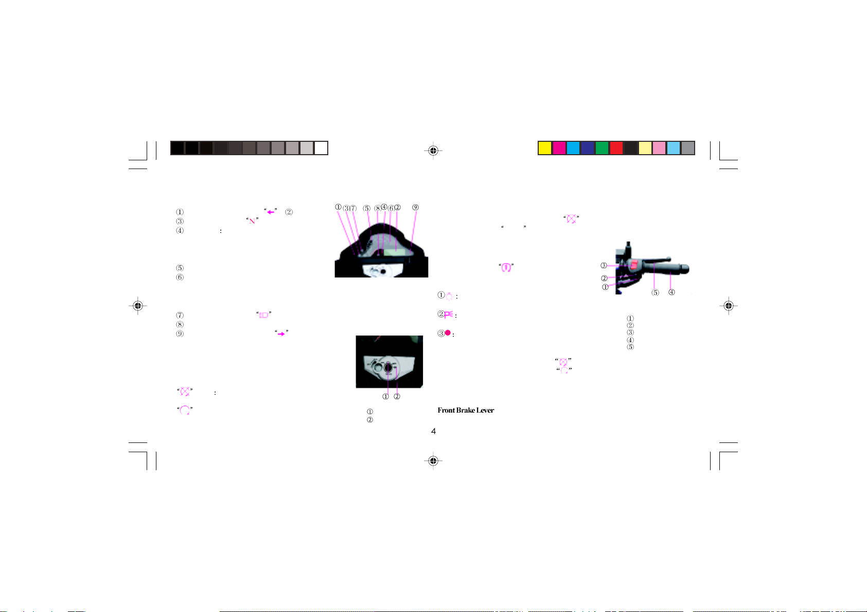
Meter and Indicators ......................................................................... 4
Ignition Switch and Steering Lock ................................................. 4
Right Handlebar Controls ................................................................ 4
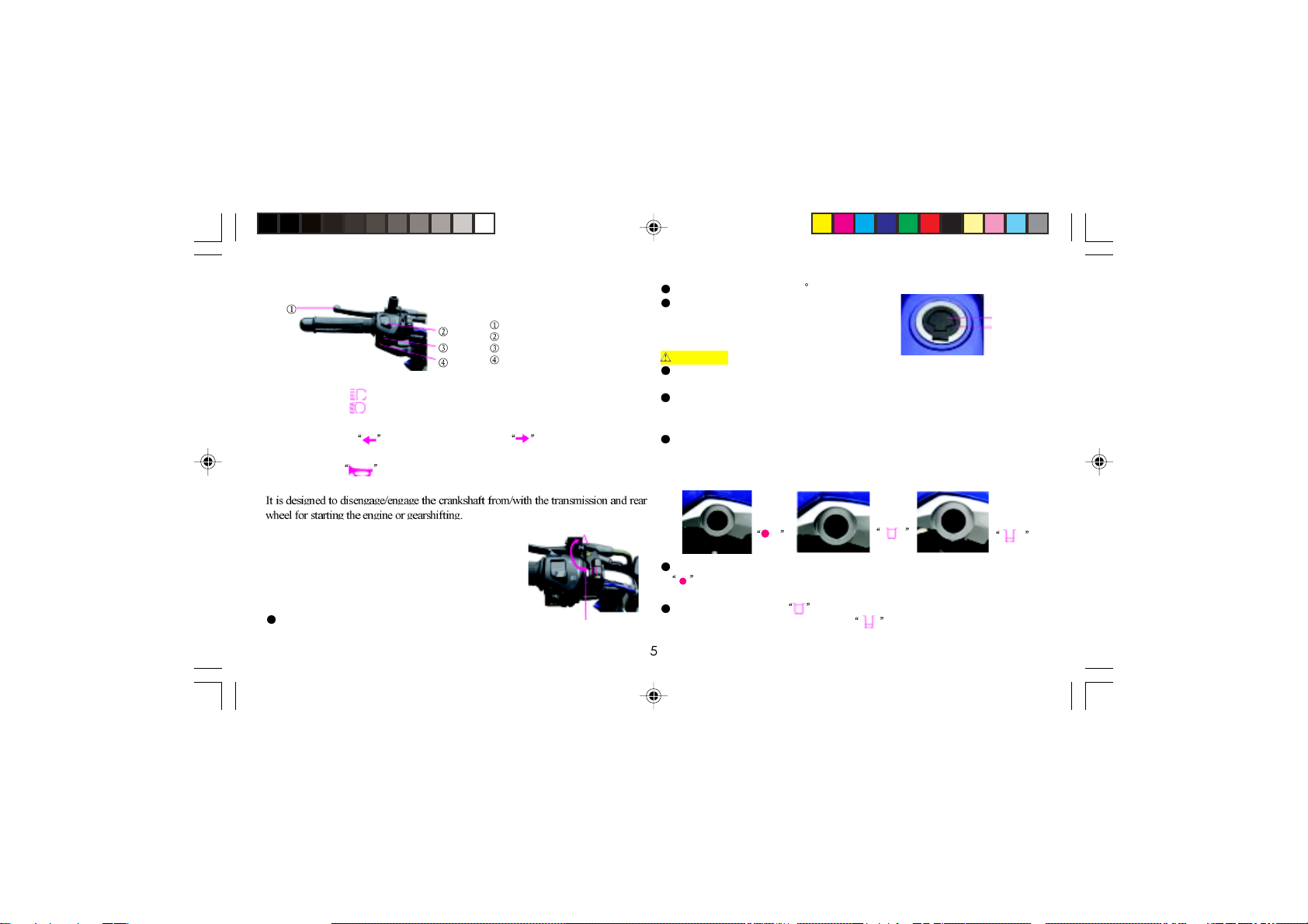
Left Handlebar Controls ................................................................... 5
Choke Lever ....................................................................................... 5
Refueling and Cap ............................................................................. 5
Fuel Cock............................................................................................ 5
Gearshift Pedal .................................................................................. 6
Rear Brake Pedal ................................................................................ 6
Rear Shock Absorber ........................................................................ 6
Stands ................................................................................................. 6
Principle of Fuel Evaporating Systerm (EP) .................................. 7
OPERATION GUIDE
Pre-ride Inspection............................................................................ 7
Starting the Engine ........................................................................... 7
Breaking-in ........................................................................................ 8
Riding ................................................................................................. 8
Braking and Parking ......................................................................... 8
MAINTENANCE
Tool Kit ............................................................................................... 9
Maintenance Schedule ...................................................................... 9
Engine Oil (EP) ................................................................................... 10
Coolant ............................................................................................... 10
Servicing of Cooling System ............................................................ 11
Clear away Carbon Deposit (EP) ....................................................... 11
Spark Plug (EP)................................................................................. 11
Air Cleaner (EP) ................................................................................ 11
Valve Clearance .................................................................................. 12
Exhaust Muffler .................................................................................. 12
3-Way Catalytic Converter (EP) ........................................................ 12
Fuel Filter ........................................................................................... 13
Operation of Throttle ........................................................................ 13
Idle Speed of Carburetor (EP) ......................................................... 13
Check Leaks along Air Supply (EP)............................................... 13
Clutch ................................................................................................. 13
Drive Chain ........................................................................................ 13
Front Brake ......................................................................................... 14
Rear Brake ........................................................................................... 15
How to Check and Replace Brake Pad ............................................ 15
Front/Rear Shock Absorber and Suspension ................................. 15
Tyre ...................................................................................................... 15
Front Wheel ....................................................................................... 16
Rear Wheel ......................................................................................... 16
Fuse ..................................................................................................... 16
Battery (EP) ....................................................................................... 16
TROUBLESHOOTING AND STORAGE
Troubleshooting................................................................................ 17
Cleaning and Storage ........................................................................ 17
Removal from Storage ........................................................................ 17
Anti-fall-over Device (Optional) .................................................... 17
Motorcycle Alarm (Optional) .......................................................... 18
ELECTRIC DIAGRAM ......................................................................... 19
SPECIFICATIONS .................................................................................. 20
LF 150-10B(ENGLISH)A.p65 2012-4-23, 9:333

SAFE RIDING RULES
WARNING Motorcycle riding requires special efforts on your part to ensure
safety. Know these requirements before you ride.
Always make a pre-ride inspection before you start the engine. You may prevent
accident or equipment damage.
Most countries require a special motorcycle riding test or license. Make sure you are
qualified before you ride. NEVER lend your motorcycle to an inexperienced rider.
Make yourself conspicuous to help avoid the accident that wasn’t your fault:
Wear bright or reflective clothing.
Don’t ride in another motorist’s “blind spot”.
Don’t speedily cross another’s way.
Obey all national and local laws and regulations.
Obey the speed limits, and NEVER travel faster than conditions warrant.
Signal before you make a turn or lane change to draw other motorists’ attention.
Use extra caution at intersections, parking lot entrances and exits.
Always remember to ride with both hands and keep both feet on the rider footrest while
the passenger grasps the handrail with both feet on the rear footrest.
PROTECTIVECLOTHS
For the safety sake, always wear a helmet, a face shield, dust glasses and protective
clothing. Your passenger needs the same protection.
The exhaust system becomes hot during operation, and it remains hot for a while after
stopping the engine. Take care not to touch the exhaust system while it is hot. Wear
clothing that fully covers your legs.
Do not wear loose clothing that could catch on the control levers, wheels, etc.
REFITTING
WARNING Arbitrarily refitting the motorcycle or removing the original parts
MOTORCYCLE SAFE RIDING
may make riding unsafe, and is illegal also. The user must obey all national and local
laws and regulations in relation to vehicle and traffic. If you have a good proposal
concerning refitting of the motorcycle, please write us. The refitment can be done with
permission of the Co. Otherwise, the user will take the consequences.
LOADING
WARNING Addition of accessories and cargo may reduce the motorcycle’s
stability, performance and safe operating speed.
Keep cargo and accessory weight lower and close to the center of the motorcycle. Load
weight equally on both sides to minimize imbalance. As weight is located further from
the motorcycle’s center of gravity, handling is proportionally affected.
Adjust tyre pressure and rear suspension to suit load weight and riding conditions.
Make sure that cargo is fastened on the vehicle.
Do not attach items to the handlebars, fork or fender. Otherwise, unstable handling or
slow steering response may occur.
The maximum load weight of the motorcycle is 150kg. Please do not overload.
ACCESSORIES
Genuine accessories of LF Motors have been specifically designed and tested on the
motorcycle. Beacuse the factory cannot test all other accessories, you are personally re-
sponsible for selection, installation and use of accessories not produced by the Co. Al-
ways follow Safe Riding Rules and these below:
Carefully inspect the accessory to make sure that it does not obscure any lights, reduce
ground clearance or banking angle, or limit suspension travel, steering travel or con-
trol operation.
Do not add electrical equipment that will exceed the motorcycle’s electrical system
capacity.
LF 150-10B(ENGLISH)A.p65 2012-4-23, 9:334

PARTS LOCATION (Fig. 1-3) Fig. 1 (Left-view) Fig. 2 (Right-view)
Exhaust muffler Main step Radiator Front wheel Front shock absorber
Front winker Headlight Meter Rear shock absorber Front brake Gearshift pedal Center stand Side stand Rear wheel Rear winker
Pillion rail Seat Fuel tank Front fender Rearview mirror
GENERALINFORMATION
LF 150-10B(ENGLISH)A.p65 2012-4-23, 9:335

VIN RECORD (Fig. 4-6)
VIN:
Engine Code:
Engine Model
Fig. 7
VIN Engine Code Nameplate
Fig. 3
Rearview mirror
Tachometer
Fuel gauge
Odometer
Throttle grip
Left grip
Handlebar controls, RH
Handlebar controls, LH
Fuel tank lock
Ignition switch
Please fill the VIN and engine code of your motorcycle in the blank below. They will help
order spare parts and find out the vehicle when stolen.
The VIN is stamped on the right of the steering stem (Fig. 4).
The engine code is stamped on the bottom-left of the crankcase (Fig. 5).
The vehicle nameplate is fixed on the mid of the steering stem (Fig. 6).
Fig. 4 Fig. 5 Fig. 6
FUELAND ENGINE OIL(EP)
Fuel Selection
Fuel is a key factor in deciding the exhaust emissions
from the engine, so selection of fuel must follow the
rules below. Selected fuel must be unleaded gasoline with
octane No. RQ-93 or higher. Using improper fuel could
reduce performance, shorten the engine’s service life.
Engine Oil Selection (Fig. 7)
The quality of the engine oil plays a vital role in deciding
the engine performance and service. Engine oil must be
selected in accordance with rules below and other oils, such as ordinary engine oil, gear
oil and vegetable oil, are forbidden to be used.
The vehicle has been filled with engine oil SAE15W/30-SE before being delivered. The
lubricant is only suitable at a temperature range within 20 35 . If other motor oil
is to be used instead, the alternative must be technically equivalent in every respect.
Viscosity varies with regions and temperatures, so the lubricant has to be selected accord-
ing to our recommendation.
If there is no gasoline engine oil SAE15W/40-SE, the engine oil No. HQB-10 (or HQB-
6 in regions where the temperature is lower than 10 ) can be used instead.
LF 150-10B(ENGLISH)A.p65 2012-4-23, 9:336

RIGHT HANDLEBAR CONTROLS (Fig. 10)
Starter Button
Depress the button to start up the engine.
Headlight Switch
The 3-position switch functions as follows:
The headlight, taillight and meter lights are
bright.The parking light, tailight and meter lights are
bright.
(OFF) The headlight, taillight, parking light and
meter lights are off.
METER AND INDICATORS (Fig. 8)
Left turn signal indicator Odometer
Neutral indicator
Fuel gauge shows fuel amount remained in the
tank. With the pointer facing F, fuel amount is 13L.
When the pointer is near red zone, the remainder is
only 2.8L, in this case, add fuel as soon as possible.
Tachometer
Red zone ( of tachometer) means that the engine runs
at a top limit speed, in this case, service life of the
engine will be shortened. Fig. 8
Fig. 10
Starter button
Headlight sw.
Emergency sw.
Throttle grip
Front brake lever
Fig. 9
Ignition sw.
Steering lock
CONTROLLING PARTS
IGNITION SWITCH AND STEERING LOCK
(Fig. 9)
Ignition Switch
The ignition switch is equipped with 2 keys inclucing a spare
one. OFF Engine and lights cannot be operated and the
key can be removed.
ON: Engine and lights can be operated, neutral light
“N” is lit and the key cannot be removed.
Steering Lock
To lock the steering head, turn left or right the steering bar as far as it will go, insert the
key into the ignition switch slot, turn to (OFF) position, then depress and turn
counterclockwise to LOCK position, at last remove the key. To unlock the steering
head, turn the key clockwise.
EmergencySwitch
In an emergency, setting the switch to will stall the engine at onec.
In normal riding cases, always set it at .
Throttle Grip
The grip is used to control the engine power. Turning toward in the grip will increase fuel
supply, while turning toward out it will decrease fuel supply.
Grasping in the lever will apply the front brake.
CAUTION Do not let the pointer face to the red zone with the engine running.
High beam indicator
Water temperature alert
Right turn signal indicator
LF 150-10B(ENGLISH)A.p65 2012-4-23, 9:337

LEFT HANDLEBAR CONTROLS (Fig. 11)
Headlight Dimmer Switch
Push the switch to to select high beam.
Push the switch to to select low beam.
Turn Signal Switch
Move the switch to to signal a left turn; and to to signal a right turn.
Horn Button
Press the button to sound the horn.
ClutchLever
Cap lock
Fuel filler cap
ON
Fig. 12 Choke lever
Fig. 13
Fig. 14
Fig. 11
Clutch lever
High beam dimmer sw.
Turn signal switch
Horn button Do not overfill the tank (there should be no fuel in the filler neck). After refueling,
make sure the fuel filler cap is closed securely.
Gasoline is extremely flammable and is explosive under certain conditions. Refuel
in a well-ventilated area with the engine stopped. Do not smoke or allow flames or
sparks in the area where the fuel tank is refueled.
Before refueling, make sure to filter fuel first. Spilled fuel vapor may ignite. If any
fuel is spilled, make sure the area is dry before starting the engine.
KEEP OUT OF REACH OF CHILDREN.
FUEL COCK (Fig. 14)
The 3-way fuel cock is on the bottom-left side of the fuel tank. With the fuel cock in the
position, fuel cannot flow from the tank to the carburetor. Turn it OFF whenever
the motorcycle is not kept in use.
With the fuel cock in the position, fuel will flow from the main fuel supply to
the carburetor.With the fuel cock in the position, fuel flow the reserve fuel
supply to the carburetor. Use 2.8 L of reserve fuel only when the main sypply is gone.
CHOCK LEVER (Fig. 12)
The choke lever is located in the left-front of the handlebar.
The choke set in position A is fully open, in position B
half-open and in position C fully closed.
REFUELING AND FUELFILLER CAP
Opening of Cap (Fig. 13)
The fuel filler cap is located on the front of fuel tank. Insert
the ignition key.
Turn the key clockwise by 90 .
Remove the cap.
To reinstall the cap, depress it onto the tank inlet in
position, then turn and remove the key. The fuel tank
capacity is 13L including the reserves supply of 2.8 L.
WARNING
OFF RES
LF 150-10B(ENGLISH)A.p65 2012-4-23, 9:338

Gearshift pedal
Fig. 15
5-speed non-cyclical pattern Fig. 16
It is forbidden to
gearshift up or
down when the
throttle is still not
decreased and
clutch is in.
Fig. 17
Rear brake
pedal
Fig. 18
Fig. 20
Fig. 19
REAR BRAKE PEDAL (Fig. 17)
The rear brake will function and the rear stop
light will glow when applying the pedal.
REAR SHOCK ABSORBER (Fig. 18)
The shock absorber has 5 adjustment positions
for different loads and riding conditions.
STANDS
Side Stand (Fig. 19)
When parking the vehicle, turn the side stand clockwise along the frome to position.
Before driving the vehicle, turn the stand to the initial position
CAUTION Be sure to set the stand to position B before driving the motorcycle.
Otherwise, it may fall over.
Center Stand (Fig. 20)
When parking the vehicle, step on the center stand at the left of body while rising the rear
portion of body with right hand so as to support the motorcycle. Before driving the
vehicle, move the steering head forward to let the center stand return automatically.
Refuel at the earliest opportunity.
CAUTION After refueling, return the fuel cock to ON
position. Otherwise, you mayrun out of fuel with no reserve.
Learn how to operate the fuel cock when riding the
motorcycle.
GEARSHIFT PEDAL (Fig. 15 & 16)
The motorcycle is equipped with a 5-speed mesh
transmission. The gear indicator shows the gear position at
present.
The shifting patterns are as shown in the Fig.16
Position I is for light loads and smooth road conditions. Position II to V increase spring
preload for a stiffer rear suspension, and can be used when the motorcycle is heavily
loaded or ridden in rugged roads.
NOTE Be certain to adjust shock absorbers both left and right to the same position.
LF 150-10B(ENGLISH)A.p65 2012-4-23, 9:339

OPERATIONGUIDE
PRE-RIDE INSPECTION
Inspect your motorcycle every time before you ride it. The items listed here will only take
a few minutes to inspect, and in the long run they can save time, expense, and possibly
your life.
1. Engine oil level - add engine oil if required. Check for leaks.
2. Fuel level - fill fuel tank when necessary. Check for leaks.
3. Coolant level - fill the reverse when necessary. Check for leaks.
4. Front and rear brakes - check operation and adjust free play if necessary.
5. Tyres - check condition and pressure.
6. Battery eletrolyte - check that the electrolyte is suitable.
7. Throttle - check for smooth opening and full closing in all steering position.
8. Lights and horn - check that headlight, tail/brake light, winkers, parking light, indi-
cators and horn function properly.
9. Drive chain - check condition and slack. Adjust and lubricate if necessary.
10. Steering system - check for its smoothness and reliability.
11. Fastener - check that all nuts, screws and bolts are mounted securely.
Correct any discrepancy before you ride. Contact your dealer for assistance if you cannot
correct the problem.
STARTING THE ENGINE
WARNING Do not start the engine in a narrow area to prevent accidents. The
exhaust contains poisonous carbon monoxide (CO) gas that cause loss of conscious-
ness and lead to death.
PRINCIPLE OF FUEL EVAPORATING SYSTEM (EP)
Fuel Evaporating System (See attachment below)
System working priniple: mainly consists of an adsorption and a desorption process.
When the fuel evaporation comes out from the fuel tank, the evaporation is absorbed and
storaged by active carbon in the canister via pipe to make sure no it let off into the
atmosphere. After starting the engine, inhale a certain amount of fresh air from the can by
negative pressure via intak pipe, make the fuel moleucles of active carbon surface are
sucked into the engine for burning, relying on these fresh air dirve between the flow of
activie carbon.
LF 150-10B(ENGLISH)A.p65 2012-4-23, 9:3310

RIDING
Start the engine and warm up it.
While the engine idling, pull in the clutch lever and push down the gearshift pedal to
shift into low (1st) gear.
Slowly release the clutch lever and at the same time gradually increase engine speed by
opening the throttle.
When the motorcycle attains a steady speed, close the throttle, pull in the clutch lever
and shift to 2nd gear by treading the gearshift pedal.
This sequence is repeated to progressively shift to higher gears.
Coordinate the throttle with brakes for smooth deceleration.
Both front and rear brakes should be used at the same time and should not be applied
strongly enough to lock the wheel, or braking effectiveness will be reduced and control
of the motorcycle be difficult.
CAUTION
It is forbidden to gearshift up or down when the throttle is still not decreased and the
clutch is in. Otherwise, damage to the engine, chain and other parts may occur. Make
sure the gearshift pedal is operated gently and exactly. Riding with your foot resting
onthebrakepedalmaysuddenlychangeaspeedand/ordamagethedrivingmechanism.
BRAKING AND PARKING
To stop the motorcycle, close the throttle and disengage the clutch by pulling in the
clutch lever, then smoothly operate the front and rear brakes until stopping the motorcycle.
Shift the transmission into neutral, turn the emergency switch to position. Then
set the fuel cock to position, support the motorcycle with the center or side
stand. After parking, turn the ignition switch to position and lock the
steeringlock, followed by removing the key.
Attempting to start the engine with the transmission in gear may result in damage to
equipment.
Make sure the fuel in the tank is enough. Set fuel cock to position.
Insert the ignition switch and turn it to position.
Move the gearshift pedal into NEUTRAL to light up the indicator “N” (green).
slightly turn the throttl grip, then operate the starter button to start the
engine.
By lightly turning the throttle grip, increase the engine’s rotational speed to warm up
the engine at 1500r/min approximitly until it works normally, the push the chock lever
to the fully open position.
CAUTION Do not use the electric starter for more than 5 seconds at a time. Release
the starter button for approxmately 10 seconds before pressing it again. Don’t run
the throttle grip fast and make sure that the vehicle is under the user’s guarding when
the engine is being warmed up.
NOTE Startingup the engineinregions with especiallylowairtemperature, treadthe
kick-starter pedal several timex first to run the crankshaft while the ingition key
should be at “ ” (OFF).
BREAKING-IN
Help assure your motorcycle’s future reliability and performance by paying extra attention
to how you rid during the first 1000km.
During this period, avoid full-throttle riding and loading the engine heavily, besure to
drive at speeds not more then 60% of each gear and to keep changing speed.
NOTE After the first 1000km’s, be sure to conduct maintenance so as to make in
compensation for slightly wear. The service life will be extended obviously through
such maintenance.
LF 150-10B(ENGLISH)A.p65 2012-4-23, 9:3311

MAINTENANCE
TOOL KIT (Fig. 21)
Some roadside repairs, minor adjustments and parts replacement can be performaced with
the tools available in the kit.
Screw driver grip
Double-end screw driver
Spark plug wrench
Open-ended spanner, 8 10mm
Open-ended spanner, 13 15mm
Tool bag
Socket wrench, 8
MAINTENANCE SCHEDULE
Maintenance work should be performed in light of Maintenance Schedule. Letters in the
table indicate as follows:
I: INSPECT AND CLEAN, ADJUST, LUBRICATE OR REPLACE IF NECESSARY
C: CLEAN R: REPLACE A: ADJUST L: LUBRICATE
The item should be serviced by your dealer, unless the owner has the proper tools and
is mechanically qualified. Refer to the manual.
In the interest of safety, we recommend these items should be serviecd only by your
dealer.
NOTES: Clean more frequently when riding in unusual wet or dusty areas.
At higher odometer readings, still follow the frequency intervals established in
this manual.
MAINTENANCE SCHEDULE
Fig. 21
REGULAR
SERVICE
I T E M
ODOMETER READING, km (Note )
First
1,000km 4,000km 8,000km 10,000km Remarks
Fuel line system I I I
Fuel filter C C C C
Throttle operation I I I I
Carburetor choke I I I
Air cleaner element Note C C C
Spark plug I I I I
Valve clearance I I I I
Engine oil Yearly R Every 2,000km-R
Engine oil strainer Yearly-R C
Cam chain slack A A A A
Engine idle speed I I I I
Drive chain I, L I, L I, L I, L
Battery Monthly I I I I
Brake shoes/pad wear I I I
Brake system I I I I
Brake light switch I I I I
Headlight adjustment I I I I
Clutch I I I I
Side stand I I I
Suspension I I I I
Nuts, bolts, fasteners I I I I
Wheels/spokes I I I I
Steering bearings I I
LF 150-10B(ENGLISH)A.p65 2012-4-23, 9:3312

COOLANT (Fig. 24 & 25)
1. Function
The special coolant is designed for cooling, anti-depositing and promoting the boil
point. In addition, it prevents the engine from overheating when the engine runs at idle
or lower speed, and the inside of the radiator from depositing furring. Its ice point is -40
, and boilling point 108 (under an atomspheric pressure).
ENGINE OIL (EP)
Check of Engine Oil (Fig. 22)
Check the engine oil level every use.
The dipstick is located onto the rear portion of the
right crankcase cover. The level must be maintained be-
tween upper mark and lower mark .
Place the motorcycle on a level ground with the center
stand. Remove the dipstick, wipe it clean. Reinsert and
screw in the dipstick, then remove it for checking.
Add engine oil SAE15W/40-SE to upper level mark.
Do not overfill.
Insert the dipstick. Check for leaks.
Fig. 22
Dipstick Upper mark
Lower mark
Fig.23
Engine model &
code
Drain plug
Fig. 24 Radiator cap
Reserve tank cap
Lower Mark High Mark
Fig. 25
CAUTION Running the engine with insufficient oil can cause serious damage to the
engine.
Change of Engine Oil (Fig. 23)
It is better to drain when the engine is still warmed.
Place an empty container under the engine, unscrew
the drain plug.
Shift the transmission into neutral, operate the starter
button several times so as to help empty the oil thoroughly.
Reinstall the drain plug, and tighten it up.
Pour approx. 1L of SAE15W/40-SE into the engine. Re-
start the engine, keep it idle for a few minutes, and then stall
it. Recheck the oil level, and add oil if necessary.
CAUTION When running in very dusty conditions, oil
changesshouldbeperformed more frequently than specifed
in the maintenance schedule.
NOTES
(1) The density of the prepared coolant is 55%, which can be poured
directly into cooling system. If it is no enough, do not apply
water instead.
(2) Do not mix it with other coolant.
(3) Never drink the coolant because it is poisonous.
2. Adding of Coolant
(1) Place the motorcycle on the level ground with center. Open
the radiator cap (Fig. 24) and add more coolant.
(2) Start the engine and run it at idle and high speed aternatively for
2-3 times. Add more coolant if necessary. Cover the cap securely.
(3) The reserve tank is located under the seat.
(4) Add coolant to between “L” mark and “H” mark of reserve
tank. Then put the cap.
3. Change of Coolant
Set the motorcycle on the level ground with the center stand.
Place an empty tray under the radiator, then open the radiator and
remove the hose from the radiator. After discharging out, fit the hose to initial position,
add the coolant.
LF 150-10B(ENGLISH)A.p65 2012-4-23, 9:3313

Inspect the electrodes and center porcelain for deposits, and
clean with a wire brush. If the spark plug is damaged, replace
it.
Check the spark plug gap which should be 0.90 0.05mm,
and adjust by bending the side electrode if necessary.
CAUTION The spark plug must be securely tightened.
Improperly tightened plug can become very hot and possibly
damage the engine.
AIR CLEANER (EP) (Fig. 27)
The air cleaner must be cleaned and then soaked in clean oil
at least once every 4000km’s drive. Riding in very dusty area,
the job should be done more often. See your dealer for further
information.
4. NOTES
Do not open the radiator cap just after stopping the engine. Otherwise, burn you by
aqueous vapour or boiling liquid.
Take care to discharge the coolant from the cooling system so as to prevent the crankcase
from getting liquid before maintaining the engin.
SERVICE OF COOLING SYSTEM
1. The cooling system should be checked for tightness at least once every 3000km’s
drive. Check the hoses by pressing the surfaces with finger for damage such as ageing,
cracks. If any, send it to your dealer for help.
2. Check the coolant once every 3000km’s drive as following:
(1) Check the cooland level in the radiator. The coolant may be ablated a little as the
engine runs. For adding coolant, select the same density and the same type of coolant. Do
not use water instead.
(2) Check that the coolant is clear. If it becomes cloudy or its service limit arrives, replace
it in good time.
CLEAR AWAY CARBON DEPOSIT (EP)
Clear away carbon deposit around the spark plug and piston ring, on the piston top, in
the piston ring slot and combustion chamber regularly.
SPARK PLUG (EP) (Fig. 26)
Spark Plug Type CPR8EA
Check and Replace
Disconnect the spark plug cap from the spark plug. Clean any dirt from around the
spark plug base. Remove the spark plug by the special wrench.
Side
electrode
Fig. 26
Seat lock Screw Air cleaner cover Element Fig. 27
Insert the ingition key into seat lock , turn it clociwise and remove the side cover.
Drive out screw , remove the air cleaner cover .
Take the element out of the housing.
Replace the element with a new one.
Reinstall all the removed parts well in the reverse order of removal.
LF 150-10B(ENGLISH)A.p65 2012-4-23, 9:3314

Index mark
Mark T
Fig. 28
Adjusting
screw
Locknut
VALVE CLEARANCE (Fig. 28 )
Check valve clearance when the engine is cold at the specified intervals.
Take the top view hole (for ignition timing) cap and magneto cap out of the left cylinder
head cover.
Rotate the flywheel counterclockwise until mark T on the flywheel aligns with the
index mark on the view hole. Check it is in TDC of the compression stroke by moving
the rocker arms. If they are free, it means check can be done. Otherwise, rotate the fly-
wheel through 360 .
Clearance should be 0.08mm for the intake valve and 0.12mm for exhaust valves.
If it is necessary to make an adjustment, loosen the valve lock nut and turn the adjust-
ing screw so there is a slight resistance when the feeler gauge is inserted. Then tighten
up the lock nut, and recheck the clearance.
EXHAUST MUFFLER (EP)
Clear away regularly carbon deposit in the exhaust pipe; check the exhaust pipe inside
for crack and washer for damage, and repair or replace if necessary.
WARNING Replace the gasket whenever a muffler is disassembled. The muffler
becomes very hot during operation and remains hot for a while after stopping the
engine. Be careful not to touch the muffler after stopping the engine.
3-WAY CATALYTIC CONVERTER(EP) (Fig. 29)
3-way catalytic converter is mounted on the exhaust system of motorcycle. It is designed
to decrease contaminations such as CO, HC, NOx, etc. by redox reaction to catalyst when
the exhaust gases flow through the device.
Applying the catalyst controls the pollutant emissions from the motorcycle, i.e. a chemi-
cal reaction sets in when exhaust gases pass through the converter that contains a catalyst.
The noble metal catalyst is characterised by good adhesiveness, and accelerates a chemi-
cal reaction without itself being affected. Its basic principle is as follow: pollutants in
the exhaust gases, such as CO, CH, NOx, etc, spread into micro-holes in the catalyst when
gases pass through the device, an adsorption reaction happens on the surfaces of catalyst,
as a result, converting them into harmless compounds (CO2, H2O, N2, etc.) and entering
the air. The purging efficiency of catalyst varies with temperature of, density of and speed
of gases.
Attention should be drawn to the following points during service:
1. Handle 3-way catalyst with care, don’t knock or press it, and keep away oil and dirt.
It should be stored in dry and well-ventilated place.
2. Never let acid liquid or electrolyte infiltrate into the exhaust muffler, otherwise, make
the catalyst unefficient.
3. Unleaded gasoline should be used.
Fig. 29
LF 150-10B(ENGLISH)A.p65 2012-4-23, 9:3315

Fig. 30
Strainer Cup Fuel filter
FUEL FILTER(EP) (Fig. 30)
The fuel filter is a fuel cock strainer. Remove the plug by turning it in B direction, take out
the strainer and clean it in gasoline. Reinstall the parts in the reverse order.
Throttle stop
screw
Fig. 32
Throttle grip Locknut
Adjuster Fig. 31
Plug
OPERATION OF THROTTLE (Fig. 31)
Check for smooth rotation of the throttle grip
from the fully open to the fully closed position at
both full steering position.
Measure the throttle grip free play at the throttle
grip flange. The standard free play should be
approx. 2-6mm.To adjust the free play, loosen the
locknut,turn the adjuster. Adjustment over, fas-
ten the locknut.
IDLE SPEED OF CARBURETOR (EP)
(Fig. 32)
The carburetor is installed between the engine
and air cleaner.
NOTE The carburetor has been set accurately in
factory. The user only needs to adjust idle speed
after the engine is warmed up.
Adjust idle speed with the throttle stop screw
to set idle speed at about 1500r/min. Turn the
screw in direction A will increase idle speed, in
direction B decrease idle speed.
When the engine has no idle speed or runs at a decreased speed, set the throttle stop
screw in the middle between the two limit positions to help mix air and fuel.
Run the engine again. Readjust the throttle stop screw, if necessary.
CAUTION Since the carburetor is a precision apparatus, don’t disassemble it without
the professional knowledge.
CHECK LEAKS ALONG AIR SUPPLY LINE (EP)
Check regularly air supply line, specially such as the joint between the muffler and engine,
the joint between the air cleaner, carburetor and inlet pipe, etc. for leakage, and repair or
replace damaged parts once there are some troubles to assure a normal air supply, and avoid
polluting the environment.
ADJUSTMENT OF CLUTCH (Fig. 33)
Measure the clutch lever free play at the clutch lever flange. The free play should be 10
20mm. Adjustment of the clutch should be done with the engine stalled.
Turn loose the locknut at the clutch cable holder located on the crankcase, and then
make adjustment by screwing in or out the corresponding adjusting nut. After adjustment,
tighten up the locknut.
DRIVE CHAIN (Fig. 34)
Check
Check the drive chain for wear and slack. Lubricate the chain if it seems to be dry.
Slack should be 10-20mm. Support the motorcycle with the center stand, check slack in
the lower chain run midway between the sprockets.
Fig. 33
Locknut
Clutch cable holder
Boot
LF 150-10B(ENGLISH)A.p65 2012-4-23, 9:3316

Fig. 34
Chain clip Adjusting bolt Locknut
Index mark Rear axle locknut Chain
Max. 10-20mm
Adjustment
Loosen the rear axle nut and locknut, turn both adjusting bolts until the chain slack
meets the standard, and make sure left and right adjusters align with the same index marks.
After checking, tighten up the rear axle nut with a torque of 50 60N.m.
NOTE Turning the adjusting nut in direction A will increase the chain slack, and in
direction B decrease the slack.
Check the chain for slack
If slack of chain is changed, it is necessary to relocate the rear wheel, for adjustment
will affect the rear brake pedal free play.
Lubrication
Pull out the chain clip with pliers, remove the joint and chain. Wash the chain in cleansing
solution and dry it in the air. Check the chain including link plates, bushings, and rollers
for damage, cracks, wear-out. Replace if necessary. Lubricate the chain, then reinstall and
adjust it.
CAUTION The chain clip should be so installed as to make sure that its closed end faces
the direction of wheel rotation.
FRONT BRAKE
Front Disk Brake (Fig. 35)
Fr. brake lever Brake main cylinder Sight glass Screw Cover Brake calliper
The front brake lever is located at the right handlebar. The distance the front brake lever
moves before the brake starts to engage is called free play, which should be 10-20mm (Fig.
35).
Place the motorcycle on the level ground. Check the brake fluid level through the sight
glass. If the fluid level is below the LOWER, loosen the cylinder cover screws, remove
the cover, add brake fluid up to the UPPER level mark.
Air Bleeding
If the brake lever free play becomes excessive and the brake pads are not worn beyond its
minimum depth, there is probably air in the brake system and bleed it as follows:
Pump the front brake lever, then gently loosen the bleed valve while holding the lever.
Take care to tighten up the bleed valve as soon as flowing fluid. Repeat above the proce-
dure until the system is completely bled.
Apply the breke several times and check for free wheel rotation after the brake lever is
released.
WARNING Apply only specified brake fluid, or braking effectiveness and riding
safety will be affected adversely. Do not allow contaminants such as dirt or water to
enter the brake fluid tank. Brake fluid may cause irritation.Avoid contact with skin
or eyes. In case of contact, flush thoroughly with water.
Wear limit
Fig. 35
LF 150-10B(ENGLISH)A.p65 2012-4-23, 9:3317

REAR BRAKE (Fig. 36)
Support the vehicle on its center stand. Measure the distance the rear brake pedal moves
before the brake starts to engage. The free play should be 20 30mm.
Apply the brake several times and check for free wheel rotation after the brake pedal is
released.
NOTE There are no adjustments to be made to the brake. For any doubt, see your dealer
for help.
HOW TO USE BRAEK WEAR INDICATOR (Fig. 37 & 38)
If any pad is worn to its limit depth, replace both pads as a set at the first opportunity.
Rear brake pedal ~Fig. 36
Fr. brake disk
Fr. brake caliper Rr. brake disk
Rr. brake caliper
Wear limit
Wear limit
Fig. 37 Fig. 38
Tyre Pressure
Rider Front tyre: Rear tyre:
Rider & passenger Front tyre: Rear tyre:
Tyre size Front tyre: Rear tyre:
Tread Depth Limits
Front tyre Rear tyre
FRONT/REAR SHOCK ABSORBER AND SUSPENSION
Support the motorcycle on the center stand, pull in the front brake lever to lock the front
wheel, pump the front/rear shock absorber up and down several times to see that it func-
tions well without noise or leakage.
Check the rear fork bushing for proper play by pressing the side of the rear wheel. Make
sure that all of the fasteners are tightened securely.
NOTE If the shock absorber is damaged, repair or replace it.
TYRE
Proper air pressure will provide maximum stability, riding comfort and porlong tyre life.
WARNING Operation with excessively worn tyres is hazardous and will adversely
affect traction and handling.
NOTE Tyre pressure should be checked before you ride while the tyres are “cold”. Check
the tyres for cuts, embedded nails, or other sharp objects. Check the rims for dents or
deformation. See your deler for change or damaged tyres or punctured inner tubes.
CAUTION Improper tyre inflation will cause abnormal tread wear and create a
safety hazard. The tyre pressure less than the rated value may result in slipping wheel
on the ground or coming off from the rim.
When the tread depth in the middle section of tyres reached limits below, please replace
them.
LF 150-10B(ENGLISH)A.p65 2012-4-23, 9:3318

Installation shall be done in the reverse order of
removal.
NOTES
Tightening torque of rear axle nut: 50 60N.m
For adjustment of the rear brake and chain, refer to
related items prescribed in the manual.
FUSE (Fig. 41)
The fuse is positioned behind the left side cover near
the battery stay. The fuse will blow to protect the cir-
cuit automatically in the case of troubles such as a
short circuit or an overload trouble. After the
troubleshooting, fit a new fuse available in the fuse
box.
Fig. 39
Front axle
Speed sensor
Fig. 40
Locknut
Rear axle
Fuse
Fig. 41
BATTERY (EP) (Fig. 42)
The battery is located behind the left cover of vehicle.
Maintain it in accordancde with the Maintenance Sched-
ule in the manual. The battery electrolyte level should be
between the UPPER level mark and LOWER level mark.
Should battery electrolyte level be below the LOWER
level mark, add proper distilled water to the UPPER level
mark. Be careful not to exceed the UPPER mark when
adding distilled water. Otherwise, overflowing electrolyte may cause corrosion.
CAUTION Be sure not to discard the battery electrolyte or used battery. Handle in
accordance with national or local environmental protection rules. Avoid entering water
around the battery when washing the vehicle.
WARNING If the battery is to be removed, disconnect the negative lead “ ” from the
battery terminal first, and then the position lead “+”. Connection should be done in the
reverse order of removal. Do not touch the positive lead to the vehicle body to prevent short-
circuiting. The leads should be tightened securely, or spark may occur to cause a fire.Make
sure that the duct of battery keeps unblocked, or the battery may be explosive under
certain conditions. The battery, in addition, should be equipped with an exhaust pipe,
otherwise, overflowing electrolyte (sulfuric acid) may erode the vehicle body, main cable,
even causing a fire by short-circuiting.
CAUTION The battery contains sulfuric acid (electrolyte). Contacting with skin
or eyes may cause severe burns. If such case occurs, flush with water for at least 5 minutes
and call a physician immediately. Please protective clothing and a face shield. Keep out
of reach of children. Do not use a new battery until taking a 30-minute wait after adding
liquid. If the engine fails to be started with the electric starter and the neutral light is dim,
use the kick-starter to start the engine. For prolonging the service, please start the engine
using the kick-starter when the air temperature is lower. Charge the battery at a rate less
than 1A for 10-15 hours if necessary. For further details, refer to Operating Instructions
of Battery.
Fig. 42
FRONT WHEEL (Fig. 39)
To remove the front wheel, support the motorcycle
on the center stand, loosen the lock screw, remove
the speed sensor, extract the front axle, and remove
the front wheel.
NOTES
Installation shall be done in the reverse order of
removal.
Tightening torque of front axle nut: 45 55N.m
REAR WHEEL (Fig. 40)
Support the motorcycle on the center stand, drive out bolts of brake caliper, remove the
brake caliper. Loose both locknuts, remove the chain. Unscrew the rear axle nut, remove
the rear axle and wheel in due succession.
LF 150-10B(ENGLISH)A.p65 2012-4-23, 9:3319

TROUBLESHOOTING
If the engine fails to start, do checks as follows:
1. Is there enough fuel in the tank?
2. Is fuel reaching the carburetor from the tank cock?
3. Disconnect the fuel line from the carburetor, set the tank cock to position,and
see if fuel flows out?
4. If OK, check the ignition system.
CAUTION Do not allow fuel to flow at will. Fuel should be collected in the retainer.
Do not smoke or allow flames or sparks in the area where the engine is subjected to
thecheck.
5. Remove the spark plug from the cylinder head, and connect it with the spark plug cap.
6. Fix the spark plug on the vehicle body. Turn the ignition switch on, set the emergency
switch to “ ” position. Press the start button, and see if there are sparks at the
electrode gap of the spark plug. If there are no sparks, see your dealer for help.
CAUTION
Do not conduct the said check by fixing the spark near to the cyliner head. Otherwise,
gas in the cylinder may ignite by sparks.
For safety’s sake, it is better to connect the metal portion of spark plug outer housing
with bare metal of vehicle body.
CLEANING AND STORAGE
Cleaning
1. Check if the spark plug and inlets are installed or pluged securely before cleaning the
vehicle.
2. Hose the vehicle completely.
3. Dry the motorcycle using a soft cloth or sponge.
4. Lubricate the drive chain immediately after washing and drying to prevent surfaces from
getting rusty.
5. Start the engine, and allow it to run for several minutes.
CAUTION High-pressure water can damage certain parts such as wheel bearings, front
fork, brakes, seal of transmission, electric equipment, etc. Prevent the muffler from getting
in water, the spark plug from being wetted down when washing the vehicle.
Storage
Take some measures as following when subjecting the vehicle to 60-day or more storage.
1. Empty fuel inside the fuel tank, carburetor and other pipes.
2. Drive off the spark plug, pour a bit of engine oil SAE15W/40-SE into the engine. Turn
off the ignition switch and tread the kick-pedal several times to scatter evenly the oil
inside the cylinder.
3. Remove the drive chain, clean and oil it.
4. Lubricate all of the controlling cables.
5. Block up the vehicle frame so that both the wheels clear the ground.
6. Seal the muffler outlet with a plastic bag to prevent the former against moisture.
7. Coat all surfaces of bare metal with a thin layer of rust-resisting oil if the motorcycle is
stored in moist and salty regions.
8. Dismantle the battery and store in a dry, cool and well-ventilated place. Charge the
battery monthly in course of storage.
REMOVAL FROM STORAGE
After long-term storing the motorcycle, check, adjust and service it according to require-
ments stated in the manual to make sure the motorcycle functions properly. Try the vehicle
at low speed in a safe riding area away from traffic.
ANTI-FALL-OVER DEVICE (Optional)
TROUBLESHOOTING, STORAGEAND OPTIONALPARTS
LF 150-10B(ENGLISH)A.p65 2012-4-23, 9:3320
Table of contents
Other Lifan Motorcycle manuals