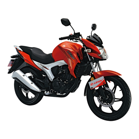
Lifan LF200-10P User manual

CONTENTS
CHAPTER 1 GENERAL
1.1 VEHICLE INTRODUCTION-------------------------------------------------------------------------------------------------------1-1
1.2 SPECIFICATIONS-----------------------------------------------------------------------------------------------------------------------1-2
CHAPTER 2 ENGINE
2.1 CYLINDER HEAD-------------------------------------------------------------------------------------------------------------------2-1
2.2 CYLINDER BLOCK-----------------------------------------------------------------------------------------------------------------2-8
2.3 VALVE TRAIN----------------------------------------------------------------------------------------------------------------------- 2-11
2.4 TRANSMISSION --------------------------------------------------------------------------------------------------------------------2-16
2.5 CRANKCASE-------------------------------------------------------------------------------------------------------------------------2-30
2.6 CRANK MECHANISM-------------------------------------------------------------------------------------------------------------2-36
2.7 STARTERS----------------------------------------------------------------------------------------------------------------------------2-40
2.8 LUBRICATION SYSTEM----------------------------------------------------------------------------------------------------------2-48

CHAPTER 3 CHASSIS
3.1 FRAME BODY-----------------------------------------------------------------------------------------------------------------------3-1
3.2 SUSPENSION SYSTEM ----------------------------------------------------------------------------------------------------------3-6
3.3 FRONT SUSPENSION ------------------------------------------------------------------------------------------------------------3-9
3.4 REAR SUSPENSION --------------------------------------------------------------------------------------------------------------3-13
3.5 FRONTAND REAR WHEELS --------------------------------------------------------------------------------------------------3-15
3.6 INTAKE SYSTEMAND EXHAUST SYSTEM -------------------------------------------------------------------------------3-21
3.7 COOLING SYSTEM----------------------------------------------------------------------------------------------------------------3-25
CHAPTER 4 ELECTRICALCOMPONENTS AND METER
4.1 CHARGING SYSTEM-------------------------------------------------------------------------------------------------------------4-4
4.2 EFI SYSTEM ------------------------------------------------------------------------------------------------------------------------4-7
4.3 IGNITION SYSTEM ---------------------------------------------------------------------------------------------------------------4-19
4.4 SIGNAL SYSTEM, METER, RADIATOR FAN AND WATER TEMPERATURE INDICATOR----------------------4-22

4.5 LIGHTING SYSTEM------------------------------------------------------------------------------------------------------------ 4-29
4.6 ELECTRIC STARTING SYSTEM ---------------------------------------------------------------------------------------------4-32
4.7 BATTERYAND FUSE -----------------------------------------------------------------------------------------------------------4-34
4.8 ELECTRICAL HORN ------------------------------------------------------------------------------------------------------------4-36
CHAPTER 5 SERVICE
5.1 ROUTINE MAINTENANCE AND ADJUSTMENT -----------------------------------------------------------------------5-1
5.2 PRE-RIDE INSPECTION -------------------------------------------------------------------------------------------------------5-4
5.3 GENERAL MAINTENANCE
5.3.1 Tool Kit ---------------------------------------------------------------------------------------------------------------5-4
5.3.2 Maintenance Schedule ----------------------------------------------------------------------------------------------5-5
5.4 STORAGE ------------------------------------------------------------------------------------------------------------------------5-6
5.5 UNPACKING---------------------------------------------------------------------------------------------------------------------5-6

FOREWORD
This manual covers the structure, operation, inspection, maintenance and repair of LF200-10P motorcycle for use by the LIFAN dealers and
qualified mechanics. With both the descriptions and figures/drawings, you may have a comprehensive understanding of the structure as well as
service and repair skill.
Lifan Industry (group) Co., Ltd. is continually striving to improve all its models. All information in this publication is based on the latest
product information available at the time of printing. LIFAN reserves the right of make changes at any time without notice and without incurring
any obligation.
No part of this publication may be reproduced without written permission.
LIFAN INDUSTRY (GROUP) CO., LTD.
March, 2016

1-1
CHAPTER 1 GENERAL
1.1 VEHICLE INTRODUCTION
The LF200-10P motorcycle is one of the lately developed products with comfortable riding, easily operation and safe transportation. Installed on the
vehicle is 165MJ-P engine which is of vertical single cylinder, 4-stroke and air cooled type. The vehicle
⑨⑧⑥⑦④⑨⑦⑥⑤④
7
①②③⑩⑤⑧②①③
①Exhaust muffler ②Main step ③Radiator ④Front Wheel ①Gearshift pedal ②Side stand ③Rear wheel ④Taillight
⑤Front shock absorber ⑥Front winker ⑦Headlight ⑤Rear handrail ⑥Fuel Tank ⑦Meter ⑧Front fender
⑧Rear shock absorber ⑨Seat ⑩Front brake ⑨Rear mirror

1-2
1.2 SPECIFICATIONS ITEM SPECIFICATIONS
Dimension and Weight
Length ×Width ×Height 2060mm×760mm×1105mm
Wheelbase 1330mm
Ground clearance 160mm
Kerb mass 138kg
Max. weight capacity 150kg
Engine
Model 165ML-P
Type Single-cylinder, 4-stroke and water-colled
Bore ×stroke 65.5mm×58.8mm
Displacement 198 ml
Compression ratio 11:1
Carburetor type / (EFI)
Air cleaner Plastic housing with paper and foam element
Lubrication Press/splash
Starting mode Electric
Max. net power 12.5kW/8000r/min
Max. torque 17N·m /6500r/min
Idle speed 1500 r/min
Riding system
Front shock absorber Telescopic type hydraulic drive
Rear shock absorber Spring type hydraulic drive
Steering bar angle ≤36°
Tyre
size/pressure
Front 90/90-17-4PR/175kPa
Rear 120/80-17-4PR/200kPa
Riding system Drive mode Chain

1-3
Turning circle dia. 4860mm
Drive Train
Clutch Wet, multi-plate type
Transmission 6-speed, constant mesh
Primary reduction 3.333
Final reduction 2.800
Gear ratio
1st 2.909
2nd 1.867
3rd 1.316
4th 1.000
5th 0.833
Drive chain Type 08MC
Link No. 126
Brake Front Disk
Rear Disk
Electrical
Ignition Inductive energy storage
Static ignition timing (°CA) 40°
Spark plug CPR8EA
Spark plug gap 0.9±0.05mm
Battery 12N9-BS
Fuse 20A
Headlight LED20W/10W
Front position light LED/2.7W
Tail/stop light LED0.3 W /1.7W
Winker 12V10W
Oil level warning light LED/8mA

1-4
High beam indicator LED/8mA
urn signal indicator LED/8mA
Meter light LED/8mA
Fuel/Oil
Fuel type RQ-93
Fuel tank Capacity 14L
Reserve 2.8L
Engine oil Brand 15W/40-SF
Capacity 1L
Damping oil Brand HQ-10
Capacity 320ml

2-1
CHAPTER 2 ENGINE
2.1 CYLINDER HEAD
2.1.1 Removal, Maintenance and Installation
1)Remove the bolt of oil passage and kick the starter rod to run the engine.
Check to see if oil flows from the view-hole. Clean the oil passage/line, if
necessary.
(NOTE: Bolt specification: M6×12 Tightening torque of bolt 8~12N·m)
2)Unscrew the fixing bolt of valve cover and remove the valve cover.
(NOTE: Bolt specification: M6×12 Tightening torque of bolt 8~12N·m)
3)Adjust the valve gap.
4)Unscrew and remove the fixing bolt M8 of cylinder head.
(Tightening torque30~40N.m)

2-2
5)Unscrew and remove the connecting bolt of cylinder head left cover and
remove the valve cover.
(NOTE: Bolt specification: M6×14 Tightening torque of bolt 8~12N·m)
6)Check the cylinder head left cover, valve cover and the gasket for damage.
Replace it if necessary.
7)Unscrew and remove the fixing bolt M6×10 of the timing driven sprocket.
Remove the timing driven sprocket and camshaft assembly.
(Tightening torque of bolt 8~12N·m)
8)Check the timing drive sprocket and camshaft assembly for wear, damage or
deformation. Replace them if necessary.

2-3
9)Structure of cylinder head assembly is as follows:
10)Unscrew and remove the connecting bolt of cylinder head.
(NOTE: Hexagon socket bolt specification: M6×14 Tightening torque of
bolt 8~12N·m)
11)Remove the cylinder head assembly.
12)Remove the split cone, valve spring and valve. Check them for wear.
Replace the worn parts if necessary.

2-4
13)Measure the width of effective sealing face. Replace the cylinder head or
valve if it is beyond the limit. Service limit:>1.6mm
14)Ream the valve seat to specified value. Replace it if it is beyond the limit.
Standard valve: intakeΦ29±0.05mm,exhaustΦ25±0.05mm
15)Measure I.D. of valve guide. If it is out of the limit, replace the worn valve
guide. Service limit: >Φ5.54mm
16)Unscrew the spark plug M10×1. Clear away carbon deposit around the
spark plug. The spark plug gap should be controlled between the scope of
0.8~0.9mm.
(NOTE: Tightening torque of spark plug M10×1:10~20N.m)

2-5
17) Unscrew and remove the bolt of thermostat and remove the thermostat.
(NOTE: Bolt specification: M6×16 Tightening torque of bolt 8~12N.m)

2-6
2.1.2 Troubleshooting to Cylinder Head
Description Damage Form Trouble Symptom of
Component Trouble Symptom of Motorcycle Remedy
Cylinder
Head
Carbon deposit in the
combustion chamber Engine overheats Clear away the carbon deposit.
Threaded hole of spark
plug is damaged
Air leakage between
spark plug and
cylinder head
Engine fails or is hard to start Repair threaded hole or replace the cylinder head
Seriously deformation
of cylinder head surface
(i.e. the deformation is out
of 0.05mm)
Air leakage between
cylinder head and
cylinder
Engine fails or is hard to start. Engine
lacks power.
Unstable idle speed
Grind the cylinder head surface or replace the
cylinder head
Defects such as pits,
erosion, etc. are found on
the contact area of valve
seat.
Air leakage between
valve and valve seat
due to improper
tightness
Do. Grind the valve seat and valve
I.D. of valve guide is
out of specification (i.e.
its I.D. is out of 5.54mm)
Valve stem-to-guide
clearance is too large
Eccentric wear of valve seat cause air
leakage of valve, hard starting of
engine, and unstable idle speed
Replace valve guide or cylinder head
Locknut of cylinder head
is not properly tightened
Air leakage between
cylinder head and
cylinder
Engine fails or is hard to start. Engine
lacks power.
Unstable idle speed
Screw up the locknut

2-7
Spark
plug
Improper gap between
electrodes Weak or no spark Engine fails or is hard to start. Engine
lacks power. Unstable idle speed
Adjust by slightly bend the side electrode till the gap
is 0.8-0.9 mm
Electrodes are jointed by
carbon deposit Weak or no spark Engine fails to start. Remove carbon deposit from electrodes
Too much carbon deposit
or over-oiled dirt around
the spark plug
Weak or no spark Engine fails or is hard to start. Engine
lacks power. Unstable idle speed Clear away carbon deposit or oiled dirt
Spark plug is damaged Weak or no spark Engine fails or is hard to start. Engine
lacks power. Unstable idle speed
Replace the damaged spark plug with a new one of
the same type
Loose park plug
Air leakage between
spark and cylinder
head
Engine is hard to start. Unstable idle
speed Tighten up spark plug
Camshaft
assembly
Excessive wear for cam Air intake and exhaust
is not smooth
Engine lacks power. Too much noise
from valve train. Replace the cam
Excessive wear for timing
driven sprocket hole
Too much clearance
between hole and shaft
Abnormal sound from camshaft
assembly Replace the timing driven sprocket
Excessive wear for
camshaft
Too much clearance
between hole and shaft
Abnormal sound from camshaft
assembly Replace the camshaft and shaft sleeve
Thermostat Thermostat is damaged or
plug is loose Poor rejection of heat Engine overheats Replace the thermostat or tighten up the plug

2-8
2.2 CYLINDER BLOCK
2.2.1 Removal, Maintenance and Installation
1)Remove the cylinder head gasket and dowel pins. Check them for damage.
Replace them if necessary.
2)Unscrew and remove the fixing bolt of water pipe. Remove the water pipe
and check the pipe for crack. Replace it if necessary.
3)Remove the cylinder block.
4)Remove the gasket (thickness: 0.5mm) of cylinder block. Check it for wear.
Replace it if necessary.
Gasket
Dowel pin

2-9
5)Remove the circlip of piston pin.(Caution: do not make the circlip falls into
the crankcase)
6)Pull out the piston pin and check it for wear. Replace it if it is out of the
service limit. Service limit: <Φ14.95mm
7) Check and measure the cylinder wall. If it is out of the service limit, replace
the cylinder. Service limit: >Φ65.55mm
8) Check the water passage for blocking.
Water inlet
CIRCLIP

2-10
2.2.2 Troubleshooting to Cylinder Block
Description Damage Form Trouble Symptom of
Component
Trouble Symptom of
Motorcycle Remedy
Cylinder Block
Seriously deformation of
cylinder joining surface
Air leakage between the
cylinder head and block
Engine fails or is hard to
start. Engine lacks power.
Unstable idle speed
Grind the cylinder head jointing surface
or replace the cylinder head
The cylinder block is worn
considerably
Cylinder block-to-piston/
piston ring clearance is too
large
Engine fails or is hard to
start. Engine lacks power.
Unstable idle speed. Thick
blue and white smoke from
the exhaust pipe
Replace the cylinder
Cylinder gasket is damaged Oil leakage between the
cylinder block and crankcase Replace the cylinder gasket

2-11
2.3 VALVE TRAIN
2.3.1 Removal, Maintenance and Installation
1)Check the intake/exhaust valve for air tightness. Grind the valve if necessary。
2)Remove the split cones, valve spring seat. Check them for wear.
Repair or replace them according to the actual situation.
3)Remove the valve spring, and check it for wear or deformation. Repair or
replace it if necessary.
4)Remove the valve stem seal, and check it for wear or damage. Replace it if
necessary.

2-12
5)Remove the intake/exhaust valve. Check them for serious wear. Replace them
if necessary.
6)Measure the margin and face of valve. If any one of the values is beyond the
service limit, replace the valve.
Face angle: 45° Margin: 1.6mm
Measure the diameter of valve stem. If it is beyond the service limit, replace the
valve. Service limit: <Φ4.95mm
7)Measure the free length of the spring. If it is beyond the service limit (outer:
<36mm inner: <34 mm), replace the spring with a new one.
NOTE: The loose wound coils face upward when installing the springs.
INTAKE VALVE EXHAUST VALVE
Table of contents
Other Lifan Motorcycle manuals