Lifasa SV030iH-2U User manual

i
WARNING
Electrical Shock Prevention
1. Do not remove the front cover when input power
is applied. Doing so can result in electric shock.
2. Do not operate the inverter with the front cover
removed. Electric shock can occur due to the
exposed high voltage terminals and capacitor.
3. Do not remove the cover except for routine
inspections or wiring, even if the input power is
not applied. The capacitor will remain charged
for a long time even when the power is not
applied.
4. Wiring and routine checkups should be
performed 10 minutes after disconnecting the
input power and after checking to see whether
the DC voltage is discharged with a tester.
(Below DC 30V)
5. Do not use a higher grounding method than the
Type 3 grounding method.
6. Only authorized personnel may perform wiring
and inspections.
7. Wire the inverter after the inverter installation.
8. Do not operate the switches with wet hands.
Doing so may result in electrical shock.
9. Electrical shock may occur if the cable insulation
is damaged. Insure proper mounting of
equipment to minimize excess stress on power
cables.
CAUTION
Fire Prevention
1. Install the inverter on a non-combustible surface.
Installing the inverter on or near combustible
materials can result in fire.
2. Disconnect the inverter when the inverter is
damaged. Failure to do so could lead to a
secondary accident and fire.
3. Do not connect a resistance directly between the
DC terminals P. N. Doing so can result in fire.
Damage Prevention
1. Do not apply voltages higher than the values
specified in this manual to the terminals. Doing
so can damage the inverter.
2. Incorrect terminal connection may damage the
inverter.
3. Incorrectly connecting the polarity (+/-) of the
terminals can damage the inverter.
4. After disconnecting, the inverter may still be hot.
Use caution to prevent the possibility of personal
injury.
!
!

ii
Other Important Precautions
Pay attention to the following items. Failure to do so
can result in damage of inverter and/or electrical
shock.
Handling and installation
1. Handle according to the weight of product.
Failure to do so can result in damage to product.
2. Do not stack inverters beyond listed
specifications.
3. Install according to specifications listed within
this manual.
4. Do not apply power to a damaged inverter or to
an inverter with missing components.
5. Do not open front cover while carrying inverter.
6. Do not place heavy items on inverter.
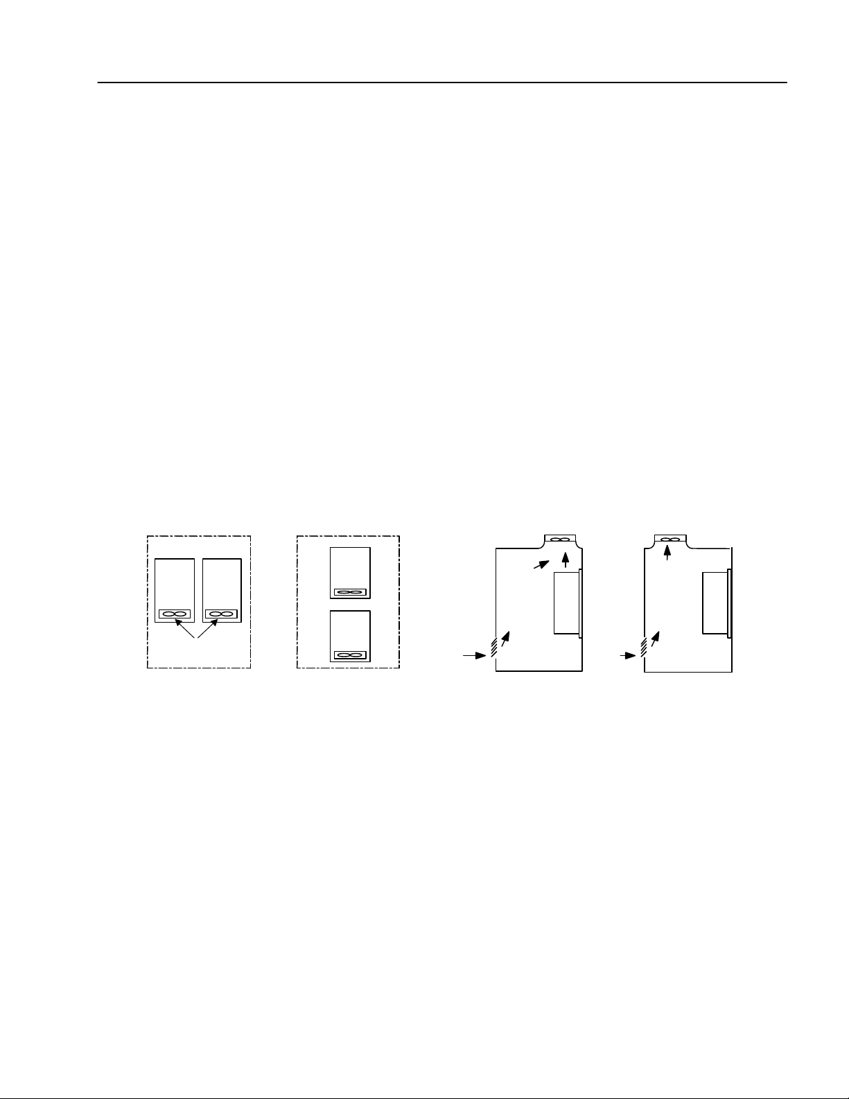
7. Installation orientation must follow specifications
listed within this manual.
8. Do not allow conducted material such as screws,
metal objects, water, or oil to enter interior of
inverter.
9. Do not drop or inflict intense impact to inverter.
10. Install and operate inverter only under specified
conditions.
11. Use hoist or crane for moving and installing iH
series inverter.
Wiring
1. Do not connect Power Factor capacitors, surge
suppressors, or RFI filters to output circuits.
2. Connect the output terminals (U, V, W) according
to specifications.
Operation
1. CAUTION: When the retry function is selected
the inverter restarts after an alarm stop.
2. Stop key on keypad can only be used when stop
key function is set. Install separate emergency
stop switch if required.
3. When run signal is received, inverter restarts
only when alarm contents have been reset.
Verify run signal before resetting alarm.
4. Do not start or stop inverter using
electromagnetic switch installed in power input
circuit.
5. Do not modify or alter anything inside inverter.
6. CAUTION: Motor might not be protected by
electronic thermal function of inverter.
7. Install noise filter to minimize potential noise
interference on equipment installed near
inverter.
8. In case of input voltage unbalance, install AC
reactor. Power Factor capacitors and generators
may become overheated and damaged due to
potential high frequency noise transmitted from
inverter.
9. Use an insulation-rectified motor or take
measures to suppress the micro surge voltage
when driving 400V class motor with inverter. A
micro surge voltage attributable to wiring
constant is generated at motor terminals, and
may deteriorate insulation and damage motor
10. Before operating unit and prior to user
programming, reset user parameters to default
settings
11. Inverter can easily be set to high-speed
operations, Verify capability of motor or
machinery prior to operating unit.
12. Stopping torque is not produced when using the
DC-Break function.Install separate equipment
when stopping torque is needed.
13. Not Provided with Over Speed Protection.
Fault Prevention Precautions
Install additional safety equipment, such as
emergency brakes, to prevent uncontrolled
machine operation from a damaged inverter.
Maintenance, Inspection, and
Exchanging Components
1. Do not conduct megger test (insulation
resistance measurement) of control circuitry in
inverter.
2. Refer to Chapter 6for routine inspection
methods.
General Precautions
The diagrams in this manual may show removed
inverter covers and removed circuit breakers. Prior to
operating unit, be sure to restore covers and circuit
breakers according to specifications.

1
Table of Contents
USER SELECTION GUIDE (iH SPECIFICATIONS).......................................................................... 3
CHAPTER 1 - INSTALLATION........................................................................................................ 6
1.1 Inspection ............................................................................................................................ 6
1.2 Environmental Conditions.................................................................................................... 6
1.3 Mounting.............................................................................................................................. 6
1.4 Other Precautions................................................................................................................ 7
1.5 Dimensions.......................................................................................................................... 8
1.6 Basic Wiring....................................................................................................................... 12
1.7 Power Terminals................................................................................................................ 13
1.8 Control Terminals............................................................................................................... 17
CHAPTER 2 - OPERATION........................................................................................................... 19
2.1 Parameter Groups ............................................................................................................. 19
2.2 Display............................................................................................................................... 20
2.3 Alpha-numerical Display .................................................................................................... 20
2.4 Procedure of Setting Data.................................................................................................. 21
2.5 Parameter Navigation ........................................................................................................ 22
2.6 Operation Method.............................................................................................................. 23
CHAPTER 3 - QUICK- START PROCEDURES............................................................................. 25
3.1 Operation Using Keypad.................................................................................................... 26
3.2 Operation Using Control Terminal – External Start, Stop and Speed Reference................ 28
3.3 Operation Using Both Keypad and Control Terminals........................................................ 30
CHAPTER 4 - PARAMETER LIST................................................................................................. 33
4.1 Drive Group ....................................................................................................................... 33
4.2 Function Group.................................................................................................................. 33
4.3 I/O Group........................................................................................................................... 37
CHAPTER 5 - PARAMETER DESCRIPTION ................................................................................ 41
5.1 Drive Group [DRV]............................................................................................................. 41
5.2 Function Group.................................................................................................................. 43
5.3 I/O Group........................................................................................................................... 66
CHAPTER 6 - TROUBLESHOOTING & MAINTENANCE.............................................................. 80
6.1 Fault Display...................................................................................................................... 80
6.2 Fault Remedy .................................................................................................................... 81
6.3 Troubleshooting................................................................................................................. 82
6.4 How to Check Power Components..................................................................................... 87
6.5 Maintenance...................................................................................................................... 88
6.6 Daily and Periodic Inspection Items ................................................................................... 89

2
APPENDIX A - FUNCTIONS BASED ON USE................................................................................90
APPENDIX B - PARAMETERS BASED ON APPLICATION...........................................................91
DECLARATION OF CONFORMITY.................................................................................................92

3
USER SELECTION GUIDE (iH SPECIFICATIONS)
200~230V Class (40 - 75HP)
Model Number SV030iH-2U SV037iH-2U SV045iH-2U SV055iH-2U
Constant Torque [HP] 40 50 60 75
Motor
Rating1Constant Torque [kW] 30 37 45 55
Constant Torque [kVA]246 55 68 83
Output
Ratings Constant Torque FLA [A] 122 146 180 220
Input Voltage 3 Phase, 200 to 230 V (±10%)
Input
Ratings Input Frequency 50 to 60 Hz (±5%)
Weight [kg (lbs)] 42 (93) 42 (93) 56 (123) 56 (123)
380~400V Class (40 - 100HP)
Model Number SV030iH-4U SV037iH-4U SV045iH-4U SV055iH-4U SV075iH-4U
Constant Torque [HP] 40 50 60 75 100
Constant Torque [kW] 30 37 45 55 75
Variable Torque [HP] 50 60 75 100 125
Motor
Rating1
Variable Torque [kW] 37 45 55 75 90
Constant Torque FLA [A] 61 75 91 110 152
Constant Torque [kVA]340 50 60 70 100
Variable Torque FLA [A] 80 96 115 125 160
Output
Ratings Variable Torque [kVA]3 52 62 74 80 103
Input Voltage 3 Phase, 380 to 400 V (±10%)
Input
Ratings Input Frequency 50 to 60 Hz (±5%)
Weight [kg (lbs)] 45 (99) 45 (99) 63 (139) 63 (139) 68 (150)
380~400V Class (125 - 300HP)
Model Number SV090iH-4U SV110iH-4U SV132iH-4U SV160iH-4U SV220iH-4U
Constant Torque [HP] 125 150 175 215 300
Constant Torque [kW] 90 110 132 160 220
Variable Torque [HP] 150 175 215 250 350
Motor
Rating1
Variable Torque [kW] 110 132 160 185 280
Constant Torque FLA [A] 183 223 264 325 432
Constant Torque [kVA]3 120 145 170 200 280
Variable Torque FLA [A] 228 264 330 361 477
Output
Ratings Variable Torque [kVA]3 147 170 213 233 307
Input Voltage 3 Phase, 380 to 400 V (±10%)
Input
Ratings Input Frequency 50 to 60 Hz (±5%)
Weight [kg (lbs)] 98 (216) 98 (216) 122 (269) 122 (269) 175 (386)
1Indicates the maximum applicable capacity when using a 4 Pole motor.
2Rated kVA (v3*V*I) is based on 220V.
3Rated kVA (v3*V*I) is based on 380V.

4
440~460V Class (40 - 100HP)
Model Number SV030iH-4U SV037iH-4U SV045iH-4U SV055iH-4U SV075iH-4U
Constant Torque [HP] 40 50 60 75 100
Constant Torque [kW] 30 37 45 55 75
Variable Torque [HP] 50 60 75 100 125
Motor
Rating4
Variable Torque [kW] 37 45 55 75 90
Constant Torque FLA [A] 61 75 91 110 152
Constant Torque [kVA]545 56 68 82 113
Variable Torque FLA [A] 80 96 115 125 160
Output
Ratings Variable Torque [kVA]5 60 70 86 93 120
Input Voltage 3 Phase, 440 to 460 V (±10%)
Input
Ratings Input Frequency 50 to 60 Hz (±5%)
Weight [kg (lbs)] 45 (99) 45 (99) 63 (139) 63 (139) 68 (150)
440~460V Class (125 - 300HP)
Model Number SV090iH-4U SV110iH-4U SV132iH-4U SV160iH-4U SV220iH-4U
Constant Torque [HP] 125 150 200 250 300
Constant Torque [kW] 90 110 132 160 220
Variable Torque [HP] 150 200 250 300 350
Motor
Rating4
Variable Torque [kW] 110 132 185 220 280
Constant Torque FLA [A] 183 223 264 325 432
Constant Torque [kVA]5 136 166 197 242 322
Variable Torque FLA [A] 228 264 330 361 477
Output
Ratings Variable Torque [kVA]5 170 200 246 270 356
Input Voltage 3 Phase, 440 to 460 V (±10%)
Input
Ratings Input Frequency 50 to 60 Hz (±5%)
Weight [kg (lbs)] 98 (216) 98 (216) 122 (269) 122 (269) 175 (386)
4Indicates the maximum applicable capacity when using a 4 Pole motor.
5Rated kVA (v3*V*I) is based on 440V.

5
All Models Max. Frequency 0.5 to 400 Hz
Output Ratings Output Voltage 3 Phase, 0 to Input Voltage
Control Method Space Vector PWM
Frequency Setting
Resolution Digital Reference: 0.01 Hz (Below 100Hz), 0.1 Hz (Over 100Hz)
Analog Reference: 0.03 Hz / 60Hz
Frequency Accuracy Digital: 0.01% of Maximum Output Frequency
Analog: 0.1% of Maximum Output Frequency
V/F Ratio Linear, Non-Linear, User Programmable
Braking Torque (w/o DB) About 20%
Overload Capacity CT 150% of Rated Current for 1 Minute, 200% for 0.5 Second
Overload Capacity VT 110% of Rated Current for 1 Minute, 150% for 0.5 Second
Control
Torque Boost Manual Torque Boost (0 to 20%), Auto Torque Boost
Operation Method Keypad / Terminal / Remote (Optional)
Frequency Setting Analog: 0 to 10 V / 4 to 20mA, Digital: Keypad
Accel / Decel Time 0.1 to 6,000 sec, 8 Pre-Defined (Programmable)
Multi-Step 8 Preset Operational Speed
Jog Jog Operation
Operating Function DC Braking, Frequency Limit, Frequency Jump, Slip Compensation, PI Control, Stall
Prevention
Operating Status Frequency Detection Level, Overload Alarm, Stalling, Over Voltage, Under Voltage,
Inverter Overheat, Run, Stop, Constant Speed, Speed Searching
Operating
Start Signal Forward, Reverse
Programmable Input 6 Programmable Inputs
Programmable Output 5 Programmable Outputs: 2 Form A Contact (N.O.)
Fault Contact Output (A, C, B) –250VAC 1A, 30VDC 1A
3 Open Collector Outputs: 24V, 50mA
Analog 4 ~ 20mA
Programmable
I/O
Meter RPM, Hz, Current, Voltage (Output Pulse: 500Hz, Output Voltage: 0 ~ 10V)
Inverter Trip Over Voltage, Under Voltage, Over Current, Inverter Overload, Fuse Open, Ground
Fault, Inverter Overheat, Motor Overheat, Main CPU Error.
Stall Prevention Over Current Prevention
Protective
Functions Instant Power Loss Less Than 15msec: Continuous Operation
More Than 15msec: Auto Restart (Programmable)
Ambient Temp. 14 °F ~ 104 °F (-10 °C ~ 40 °C), CE Certification: 41 °F ~ 104 °F (5 °C ~ 40 °C)
Storage Temp. -4 °F ~ 149 °F (-20 °C ~ 65 °C)
Humidity 90% RH Max. (Non-Condensing), CE Certification: 5 ~85% (Non-Condensing)
Altitude / Vibration Below 3,300ft (1,000m) / Below 5.9m/sec2(0.6g)
Air Pressure 86 ~ 106kPa
Application Site No Corrosive Gas, Combustible Gas, Oil Mist, or Dust
Operating
Conditions
Cooling Method Forced Air Cooling
Enclosure IP00
Inter National Standards CE Certified, UL Listed (UL508C)6
6UL is available only for 380~460V Class inverters.

6
CHAPTER 1 - INSTALLATION
1.1 Inspection
üInspect the inverter for any damage that may have occurred during shipping.
üCheck the nameplate on the inverter. Verify the inverter unit is the correct one for the application. The
numbering system for the inverter is as shown below.
LG Inverter Motor Capacity Series Name Input Voltage 380V Input
2 : 200 ~ 230V (±10%) (50/60Hz)
4 : 380 ~ 460V (±10%) (50/60Hz)
1.2 Environmental Conditions
üVerify ambient condition for the mounting location.
- Ambient temperature should not be below 14ºF (-10ºC) or exceed 104ºF (40ºC).
- Relative humidity should be less than 90% (non-condensing).
- Altitude should be below 3,300ft (1,000m).
üDo not mount the inverter in direct sunlight and isolate it from excessive vibration.
üIf the inverter is going to be installed in an environment with high probability of penetration of dust, it
must be located inside watertight electrical boxes, in order to get the suitable IP degree.
1.3 Mounting
üThe inverter must be mounted vertically with sufficient horizontal and vertical space between adjacent
equipment (A= Over 6"(150mm), B= Over 2"(50mm)).
A
A
B
B
037SV iH 4U (380V)

Chapter 1 - Installation
7
1.4 Other Precautions
üDo not carry the inverter by the front cover.
üDo not install the inverter in a location where excessive vibration is present. Be cautious when installing on
presses or moving equipment.
üThe life span of the inverter is greatly affected by the ambient temperature. Install in a location where
temperature are within permissible limits (- 10 ~ 40 ?).
üThe inverter operates at high-temperatures - install on a non-combustible surface.
üDo not install the inverter in high-temperature or high-humidity locations.
üDo not install the inverter in a location where oil mist, combustible gas, or dust is present. Install the
inverter in a clean location or in an enclosed panel, free of foreign substance.
üWhen installing the inverter inside a panel with multiple inverters or a ventilation fan, use caution.
If installed incorrectly, the ambient temperature may exceed specified limits.
üInstall the inverter using screws or bolts to insure the inverter is firmly fastened.
Inverter
GOOD (O) BAD (X)
Inverter
Cooling fan
Panel Panel
Inverter
Inverter
[When installing several inverters in a panel]
Ventilating fan
GOOD (O) BAD (X)
[When installing a ventilating fan in a panel]

Chapter 1 - Installation
8
1.5 Dimensions
1.5.1 200V ~ 230V Class
Unit: mm (inch)
VARIABLE FREQUENCY DRIVE
SV030iH-2U
SV037iH-2U
SV045iH-2U
SV055iH-2U

Chapter 1 - Installation
9
1.5.2 380V ~ 460V Class
STARVERT-iH
de energize the equipment before servicing.
-
"Risk of Electric Shock" More than one disconnect switch is required to
bus capacitors discharge.
Before opening the cover, disconnect all power and wait at least 3 minutes until DC
Do not connect the power supply to the drive output terminals (U,V,W).
Read the manual and follow the safety instructions before installation or operation.
-
CAUTION
VARIABLE FREQUENCY DRIVE
de energize the equipment before servicing.
-"Risk of Electric Shock" More than one disconnect switch is required to
bus capacitors discharge.
Before opening the cover, disconnect all power and wait at least 3 minutes until DC
Do not connect the power supply to the drive output terminals (U,V,W).
Read the manual and follow the safety instructions before installation or operation.
-
CAUTION
STARVERT-iH
VARIABLE FREQUENCY DRIVE
STARVERT-IH
STARVERT-IH
SV030iH-4U
SV037iH-4U
SV045iH-4U
SV055iH-4U
SV075iH-4U

Chapter 1 - Installation
10
STARVERT-iH
VARIABLE FREQUENCY DRIVE
STARVERT-iH
VARIABLE FREQUENCY DRIVE
STARVERT-IH
STARVERT-IH
SV090iH-4U
SV110iH-4U
SV132iH-4U
SV160iH-4U

Chapter 1 - Installation
11
STARVERT-iH
VARIABLE FREQUENCY DRIVE
STARVERT-IH
SV132iH-4U
SV160iH-4U

Chapter 1 - Installation
12
1.6 Basic Wiring
2
30/460 V
50/60 Hz
U
V
W
R
S
T
φ
3
MCCB(OPTION)
FX
RX
BX
RST
P1
P3
P4
P5
P6
CM
EG
VR
V1
I
CM
LM
+
+
FM
CM
LM
A
B
C
1A
1B
Output Frequency Meter
(0~10V pulse)
OC1
OC2
OC3
EG
P2
MOTOR
Shielded sheath
connection
Potentiometer
(10 kohm, 1/2W)
Speed signal Input
*2
Common for
FM,LM
Forward Run/Stop
2A
2B
IO
CM
Analog output
(4 ~ 20mA)
Reverse Run/Stop
Inverter Disable
Fault Reset
Multi-function Input 1
Multi-function Input 2
Multi-function Input 3
Multi-function Input 4
Multi-function Input 5
Multi-function Input 6
Common Terminal
Factory Setting:
Multi-speed and
Muti-acc/dec time
Power
supply for
speed signal:
+ 11V, 10mA
Speed signal input:
0 ~ 10V
Speed signal input:
4 ~20mA (250ohm)
Common for
VR, V1, I
Output Voltage/Current
Meter(0~10V pulse)
Fault output relay
lless than AC250V, 1A
lless than DC30V, 1A
Multi-function output relay1
lless than AC250V, 1A
lless than DC30V, 1A
Factory setting: ‘COMM’
Multi-function output relay2
lless than AC250V, 1A
lless than DC30V, 1A
Factory setting: ‘COMM’
Multi-function output 1
Factory setting: ‘STEP_L’
Multi-function output 2
Factory setting: ‘STEP_M’
Multi-function output 3
Factory setting: ‘STEP_H’
Common for
Multi-function outputs
Open
Collector
24V, 50mA
FM
N
DB Unit(Optional)
DB Resitor
P2
P1
DC Bus Choke (Optional)
3
Dynamic
Braking Unit
(Optional)
P
N
B1
B2
DC Bus Choke
DB Resistor
Note) Main Circuit Terminals Control Circuit Terminals.
1. Analog speed command may be set by Voltage, Current or both..
2. When installing the DC Reactor, the Common Busbar between P1 and P2 must be removed.
G( )G( )
(NO)
(NC)

Chapter 1 - Installation
13
1.7 Power Terminals
nType A Configuration: 230V Class (SV030iH-2U, SV037iH-2U, SV045iH-2U, SV055iH-2U)
RSTGUVWGP1 P2 N
nType B Configuration: 380 ~ 460V Class (SV030iH-4U, SV037iH-4U, SV045iH-4U, SV055iH-4U,
SV075iH-4U, SV090iH-4U, SV110iH-4U, SV132iH-4U, SV160iH-4U, SV220iH-4U)
RSTGUVWP1 P2 N
Symbols Functions
R
S
T
AC Line Voltage Input
(3 Phase, 200 ~ 230VAC or 380 ~ 460VAC)
GEarth Ground
P1
P2 Positive DC Bus Terminal
External DC Reactor (P1-P2) and DB Unit (P2-P1) Connection Terminals
NNegative DC Bus Terminal
DB Unit (N-N2) Connection Terminal
U
V
W
3-Phase Power Output Terminals to Motor
(3 Phase, 200 ~ 230VAC or 380 ~ 460VAC)
“Suitable for use on a circuit capable of delivering not more than 10,000 rms symmetrical amperes,
240 volts maximum for 230V class models and 480 volts maximum for 460V class models.”
1.7.1 Power Wiring Size
Terminals (R, S, T, U, V, W) Terminals (R, S, T, U, V, W)Model Number Wire Size (mm2)Wire Size (AWG) Model Number Wire Size (mm2)Wire Size (AWG)
SV030iH-2U 60 1/0 SV055iH-4U 38 2
SV037iH-2U 60 1/0 SV075iH-4U 60 1/0
SV045iH-2U 100 4/0 SV090iH-4U 60 1/0
SV055iH-2U 100 4/0 SV110iH-4U 80 3/0
SV030iH-4U 22 4 SV132iH-4U 100 4/0
SV037iH-4U 22 4 SV160iH-4U 100 4/0
SV045iH-4U 38 2 SV220iH-4U 100 * 2 4/0 * 2
1This P terminal is provided on optional Dynamic Braking Unit. (Refer to DB Unit Manual for detail terminal configuration)
2This N terminal is provided on optional Dynamic Braking Unit. (Refer to DB Unit Manual for detail terminal configuration)

Chapter 1 - Installation
14
1.7.2 Terminal Configuration
A Dynamic Braking Unit or a DC Bus Choke or both of them may be added to iH series inverters.
Jumper Between P1 and P2 Must Be Removed In Order
To Install a DC Bus Choke.
RSTGUVWP1 P2 N
Fig. 1–Type C Dynamic Braking Unit, DC Bus Choke Installation
WARNING
Normal stray capacitance between the inverter chassis and the power devices inside the
inverter and AC line can provide a high impedance shock hazard. Refrain from applying
power to the inverter if the inverter frame (Power terminal G) is not grounded.
!
!
Motor
3 Phase
Power Input
Dynamic
Braking
Unit
Dynamic Braking Resistor
DC Bus Choke
Refer to DB Unit Manual for
detailed terminal configuration

Chapter 1 - Installation
15
1.7.3 Wiring Power Terminals
nWiring Precautions
üThe internal circuits of the inverter will be damaged if the incoming power is connected and applied to
output terminals (U, V, W).
üUse ring terminals with insulated caps when wiring the input power and motor wiring.
üDo not leave wire fragments inside the inverter. Wire fragments can cause faults, breakdowns, and
malfunctions.
üFor input and output, use wires with sufficient size to ensure voltage drop of less than 2%.
Motor torque may drop of operating at low frequencies and a long wire run between inverter and motor.
üDo not use a 3-wire cable for long distances. Due to increased leakage capacitance between wires, over-
current protective feature may operate or equipment connected to the output side may malfunction.
üNever short between B1 and B2 terminals of the inverter.
üThe main circuit of the inverter contains high frequency noise, and can hinder communication equipment
near the inverter. To reduce noise, install line noise filters on the input side of the inverter.
üDo not use power factor capacitor, surge killers, or RFI filters on the output side of the inverter. Doing so
may damage these components.
üAlways check whether the LCD and the charge lamp for the power terminal are OFF before wiring
terminals. The charge capacitor may hold high-voltage even after the power is disconnected. Use caution
to prevent the possibility of personal injury.
nGrounding
üThe inverter is a high switching device, and leakage current may flow. Ground the inverter to avoid
electrical shock. Use caution to prevent the possibility of personal injury.
üConnect only to the dedicated ground terminal of the inverter. Do not use the case or the chassis screw for
grounding.
üThe protective earth conductor must be the first one in being connected and the last one in being
disconnected.
üGrounding wire should be at least the size listed in the following table and be as short as possible.
Grounding wire dimensions, AWG (mm²)
Motor Capacity 200V Class 400VClass
30 ~ 37kW 4 (22)6 (14)
45 ~ 75kW 2 (38) 4 (22)
90 ~ 132kW -2 (38)
160 ~ 280kW -1/0 (60)
!
!
!
!

Chapter 1 - Installation
16
nPower and Motor Connection
RSTGUVWP1 P2 N
Motor
3 Phase
Power Input
Power supply must be connected
to the R, S, and T terminals.
Connecting it to the U, V, and W
terminals causes internal damages
to the inverter. Arranging the phase
sequence is not necessary.
Motor should be connected to the
U, V, and W terminals.
If the forward command (FX) is on,
the motor should rotate counter
clockwise when viewed from the load
side of the motor. If the motor rotates
in the reverse,switch the U and V
terminals.
!
!

Chapter 1 - Installation
17
1.8 Control Terminals
1A 1B 2A 2B OC1 OC2 EG RST FX RX BX CM VR V1 V2 IO
A C B OC3 CM P1 P2 P3 P4 P5 P6 CM IFM LM CM
Type Symbol Name Description
P1 ~ P6 Multi-Function input
1~ 6 Used for Multi-Function Input Terminal.
FX Forward Run Command Forward Run When Closed and Stopped When Open.
RX Reverse Run Command Reverse Run When Closed and Stopped When Open.
BX Emergency Stop
When the BX Signal is ON the Output of the Inverter is Turned Off. When
Motor uses an Electrical Brake to Stop, BX is used to Turn Off the Output
Signal. When BX Signal is OFF (Not Turned Off by Latching) and FX Signal
(or RX Signal) is ON,Motor continues to Run.
RST Fault Reset Used for Fault Reset.
Starting Contact Function Select
CM Sequence Common Common Terminal for Contact Inputs.
VR Frequency Setting Power
(+10V) Used as Power for Analog Frequency Setting. Maximum Output is +12V,
10mA.
V1
V2 Frequency Reference
(Voltage) Used for 0-10V Input Frequency Reference. Input Resistance is 20 KO
IFrequency Reference
(Current) Used for 4-20mA Input Frequency Reference. Input Resistance is 250 O
Input signal
Analog Frequency Setting
CM Frequency Setting Common
Terminal Common Terminal for Analog Frequency Setting
FM Frequency Output
(For External Monitoring) Outputs PWM signal according to inverter Output Frequency. Maximum
Output Voltage and Output Current are 0-12V and 1mA.
Pulse
LM Current/Voltage Output
(For External Monitoring)
Outputs One of the Following: Output Current, Output Voltage. Default is set
to Output Voltage. Maximum Output Voltage and Output Current are 0-12V
and 1mA. Output Frequency is Set at 1.8kHz.
Analog
IO Frequency Output
(4 ~ 2-mA) Outputs Analog Signal according to inverter Output Frequency.
A, C, BFault Output Relay
Activates when Protective Function is Operating. AC250V,1A or less;
DC30V,1A or less.
Fault: 30A-30C Closed (30B-30C Open)
Normal: 30B-30C Closed (30A-30C Open)
1A-1B,
2A-2B Multi-Function Output Relay 1
and 2 (AUX1, AUX2) Use after Defining Multi-Function Output Terminal. AC250V,1A or less;
DC30V,1A or less.
CO1, OC2,
OC3 Multi-Function Open Collector
Output Use after Defining Multi-Function Output Terminal. DC24V, 50mA
Output signal
Contact
EG Multi0Function Open Collector
Output Common Terminal Ground Terminal for OC1, OC2, OC3.
!

Chapter 1 - Installation
18
1.8.1 Wiring Control Terminals
nWiring Precautions
üCM and EG terminals are insulated to each other. Do not connect these terminals with each other and do
not connect these terminals to the power ground.
üUse shielded wires or twisted wires for control circuit wiring, and separate these wires from the main
power circuits and other high voltage circuits.
üUse 1.25mm²(22AWG) stranded cables for control terminal connection.
nControl Circuit Terminal
The control input terminal of the control circuit is ON when the circuit is configured to the current flows out of
the terminal, as shown in the following illustration. CM terminal is the common terminal for the contact input
signals.
CAUTION
Do not apply voltage to any control input terminals(FX, RX, P1~P3, BX, RST, FM, LM, IO, CM
Etc).
24 VDC
FX
RX
CM
Current
Inverter Circuitry
Resistor
Resistor
External Sequence
!
This manual suits for next models
13
Table of contents