Table Of Contents
ABOUT THIS MANUAL....................................................................................................................................................1
Purpose............................................................................................................................................................................. 1
Scope.................................................................................................................................................................................1
SAFETY INSTRUCTIONS............................................................................................................................................... 1
INTRODUCTION...............................................................................................................................................................2
Features............................................................................................................................................................................ 2
Basic System Architecture..............................................................................................................................................2
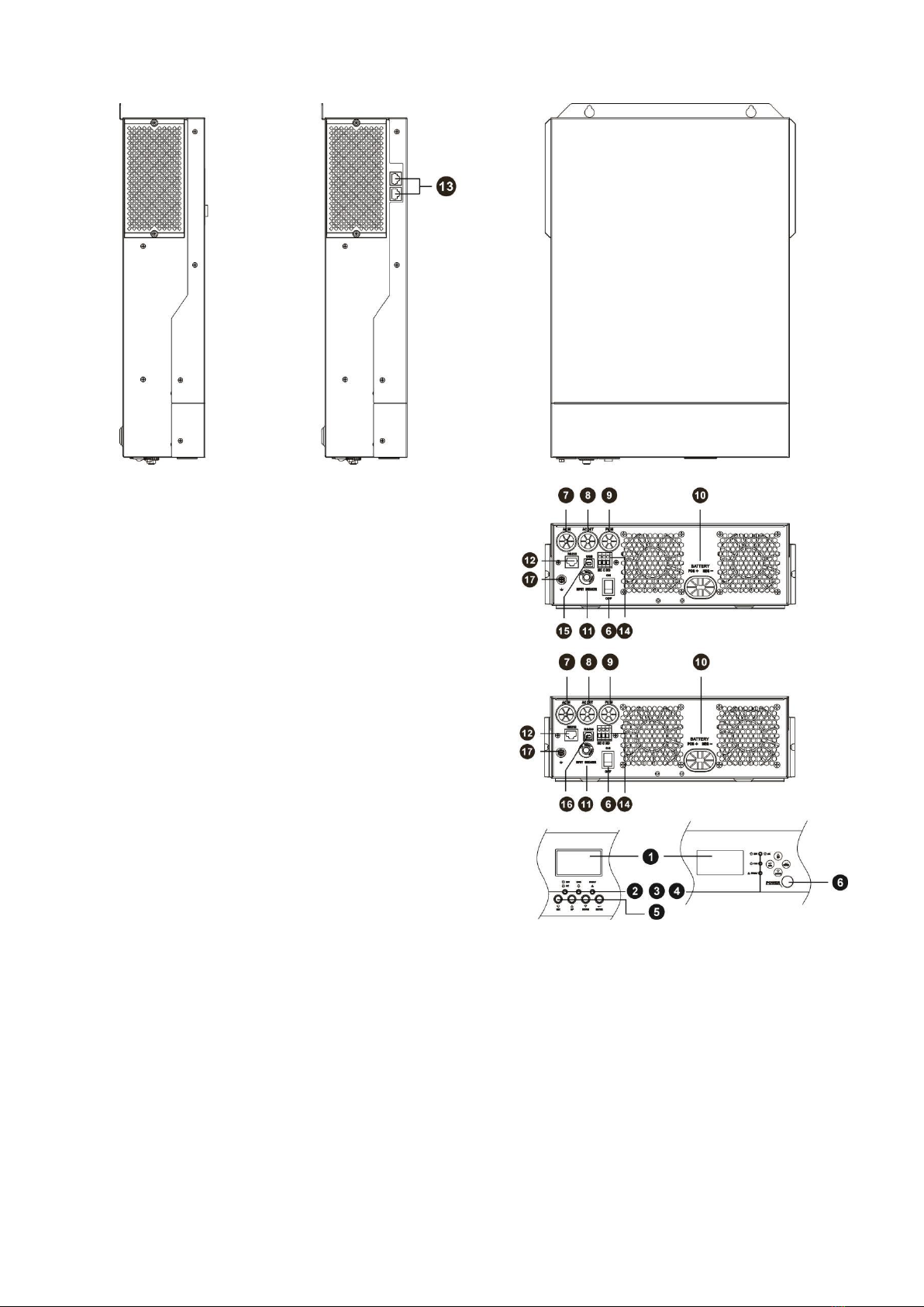
Product Overview............................................................................................................................................................ 3
INSTALLATION.................................................................................................................................................................4
Unpacking and Inspection..............................................................................................................................................4
Preparation....................................................................................................................................................................... 4
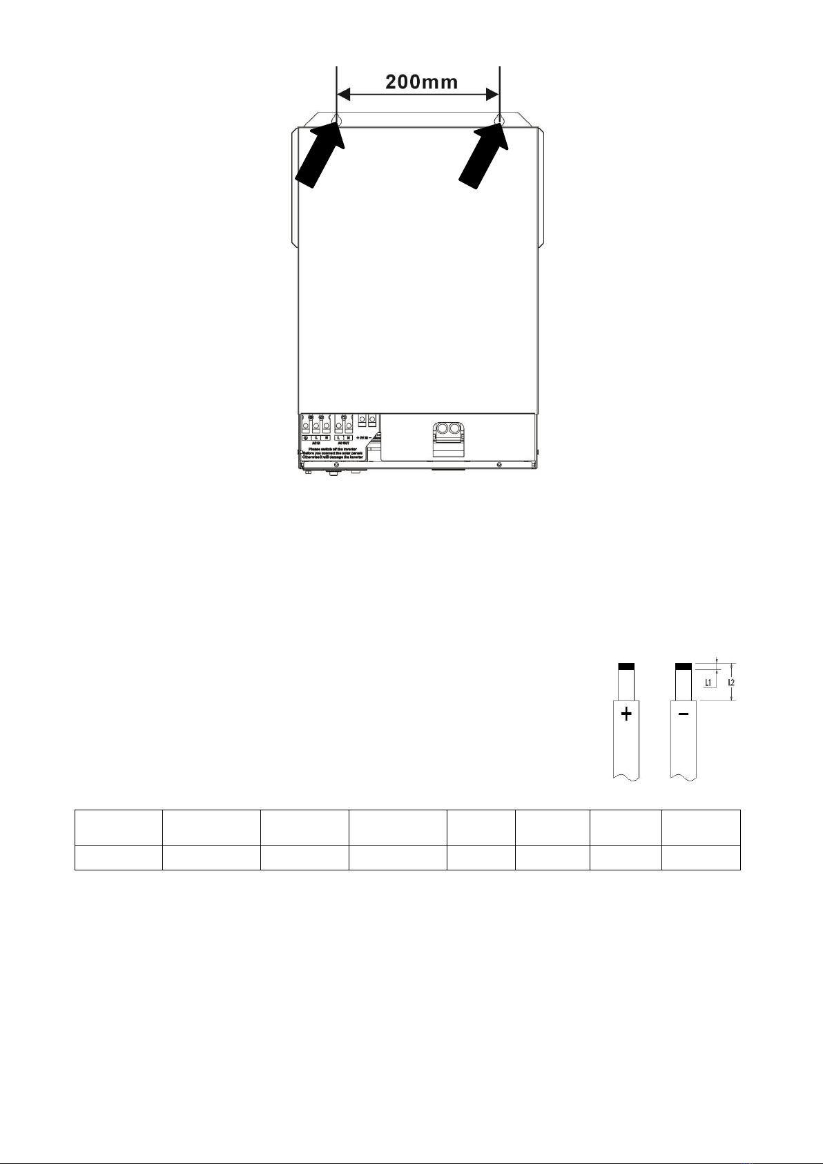
Mounting the Unit............................................................................................................................................................4
Battery Connection..........................................................................................................................................................5
AC Input/Output Connection......................................................................................................................................... 6
PV Connection..................................................................................................................................................................8
Final Assembly................................................................................................................................................................. 9
Dry Contact Signal........................................................................................................................................................ 10
OPERATION.................................................................................................................................................................... 11
Power ON/OFF............................................................................................................................................................... 11
Operation and Display Panel....................................................................................................................................... 11
LCD Display Icons......................................................................................................................................................... 12
LCD Setting.................................................................................................................................................................... 14
Display Setting...............................................................................................................................................................23
Operating Mode Description........................................................................................................................................ 26
Fault Reference Code................................................................................................................................................... 29
Warning Indicator......................................................................................................................................................... 30
BATTERY EQUALIZATION..........................................................................................................................................31
SETTING FOR LITHIUM BATTERY.......................................................................................................................... 33
SPECIFICATIONS..........................................................................................................................................................38
Table 1 Line Mode Specifications................................................................................................................................38
Table 2 Inverter Mode Specifications.........................................................................................................................39
Table 3 Charge Mode Specifications.......................................................................................................................... 40
Table 4 General Specifications.................................................................................................................................... 40
TROUBLE SHOOTING.................................................................................................................................................. 41
Parallel Installation Guide........................................................................................................................................ 42
1. Instruction................................................................................................................................................................. 42
2. Package Contents..................................................................................................................................................... 42
3. Mounting the Unit.....................................................................................................................................................42
4. Wiring Connection.................................................................................................................................................... 43
5. Parallel Operation in Single phase......................................................................................................................... 45
6. Support 3-phase equipment................................................................................................................................... 48
7. Support split phase...................................................................................................................................................50
8. PV Connection........................................................................................................................................................... 51
9. LCD Setting and Display.......................................................................................................................................... 52
10. Commissioning........................................................................................................................................................54
11. Trouble shooting.....................................................................................................................................................55