Lifesaver 6000 User manual

1
Tested & Complies to
Australian Standards
AS3786:2014
Photoelectric Smoke Alarm
AS3786:2014
Lic:SMK1377
SAI Global
MODEL 6000
• 240VAC with 9VDC battery backup
MODEL 6000RL
• 240VAC with built-in rechargeable
battery backup
240VAC mains powered
standalone and / or
interconnectable (24 units)
photoelectric smoke alarm.
Part Number:
LIF6000
LIF6000RL

2
Thank You for Purchasing this PSA Lifesaver Smoke Alarm
NOTE: Please thoroughly read this user guide and save the document for future reference
and to pass on to any subsequent owner. Important: Please read this user guide before
installation.
Teach children how to respond to the alarm and that they should never play with the unit.
Your PSA LIFESAVER Smoke Alarm is designed for use in a residential environment. It is not
designed for use in a recreational vehicle (RV) or boat.
IMPORTANT: Additional markings can be found on the back of the unit.
Model: _________________
Date Code (on back): _________________
Date of Purchase: _________________
Where Purchased: _________________
Date to Replace: _________________
Product Support: 1300 772 776
Please write down the below information
and have this at hand when you call.

3
Contents
1. Smoke Alarm: What To Do When The Alarm Sounds .....................................................................4
2. Product Features And Specifications .............................................................................................. 5
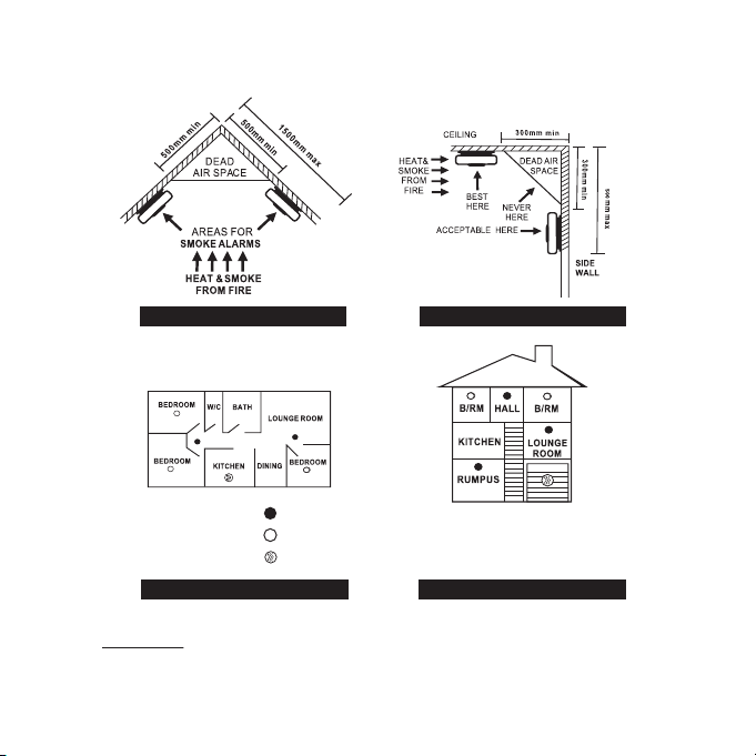
3. Recommended Locations For Alarms ..............................................................................................6
4. Locations To Avoid .........................................................................................................................8
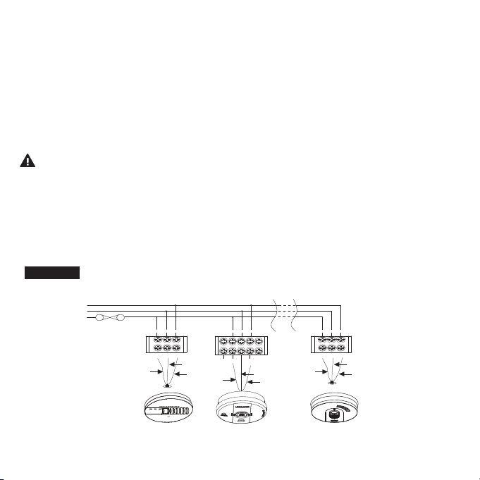
5. Installation Instructions .................................................................................................................. 9
6. Mounting Instructions ................................................................................................................. 13
7. Battery Installation, Replacement and Test.....................................................................................15
8. Operating and Testing ..................................................................................................................17
9. Visual And Audible Indications ......................................................................................................19
10. 9V Terminal and Smoke Alarm Remote Control ........................................................................... 21
11. Nuisance Alarm And HUSH .......................................................................................................... 23
12. Maintenance ............................................................................................................................... 24
13. Good Safety Habits ...................................................................................................................... 25
14. Limitations Of Smoke Alarms ....................................................................................................... 26
15. Warranty and Liability....................................................................................................................27
16.Product warranty registration..........................................................................................................28
Model: _________________
Date Code (on back): _________________
Date of Purchase: _________________
Where Purchased: _________________
Date to Replace: _________________

4
1. Smoke Alarm: What To Do When the Alarm Sounds
Smoke alarm pattern is three long beeps, a 1.5 second pause, and three long beeps repeating.
The red LED flashes every second during alarm.
•Alert small children in the home as well as anyone else who may have difficulty recognising the impor-
tance of the alarm sounding or who may have difficulty leaving the area without help.
•Leave immediately by your escape plan. Every second counts, so don’t waste time getting dressed or
picking up valuables.
•In leaving, don’t open any inside door without first feeling its surface. If hot, or if you see smoke seeping
through cracks, don’t open that door! Instead, use your alternate exit. If the inside of the door is cool,
place your shoulder against it, open it slightly and be ready to slam it shut if heat and smoke rush in.
•If the escape route requires you to go through smoke, stay close to the floor where the air is cleaner.
Crawl if necessary, and breathe shallowly through a cloth, wet if possible.
•Once outside, go to your selected meeting place and make sure everyone is there.
•Call the fire department from your mobile phone outside, or from your neighbour’s home-not from
yours!
•Don’t return to your home until the fire officials say that it is all right to do so.
•There are situations where a smoke alarm may not be effective to protect against fire.
For instance:
a) smoking in bed
b) leaving children home alone
c) cleaning with flammable liquids, such as petrol or methanol

5
2. Product Features And Specifications
This alarm detects particles of combustion using photoelectric technology. This smoke alarm has an expected
service life of ten years under normal conditions. We recommend that you should replace after 10 years from
installation date to ensure normal operation.
Product Features and Specifications:
•MODEL 6000: Powered by 240VAC (50Hz, 10 mA max, 4mA standby) hardwire with 9V replaceable battery
backup
•MODEL 6000RL: Powered by 240VAC (50Hz, 10 mA max, 4mA standby) hardwire with built-in recharge-
able battery backup
•Temperature: Operating Range: 0 °C to 40 °C
•Humidity: Operating range: up to 93% RH non-condensing
•Audible Alarm: 85+ dBA at 3m @ 3.0 to 3.5 KHz pulsing alarm
•Smoke Sensor: Photoelectric
•Smoke Alarm HUSH®Control
•Storage and Transport Conditions: -20° C to +60° C, 5-95%RH (non-condensing)
•Interconnectable up to 24 units
•Insect mesh protection over sensor.
•Quick slide base plate for easy installation
•Low battery hush for 8 hours.
•Initiating alarm memory feature.
•Chamber fault monitoring
•Approved to AS3786:2014 Australian Standard

6
3. Recommended Locations For Alarms
• Check specific State legislation in your area to ensure smoke alarms are correctly located
according to local laws. Each State or Territory may differ in building codes and regulations.
PSA Products can only recommend the locations.
• Locate an alarm for each separate sleeping area in the immediate vicinity of the bedrooms.
Try to monitor the exit path as the bedrooms are usually farthest from an exit. If more than one
sleeping area exist, then install additional alarms in the immediate vicinity of each sleeping area.
• Locate additional alarms to monitor any stairwells because stairwells act like chimneys for smoke
and heat.
• Locate at least one alarm on every floor level.
• Locate an alarm in every room where a smoker sleeps.
• Locate an alarm in every room where electrical appliances are operated (i.e. portable heaters or
humidifiers).
• Locate an alarm in every room where someone sleeps with the door closed. The closed door
may prevent an alarm not located in that room from waking the sleeper.
• Smoke, heat and other combustion products rise to the ceiling and spread horizontally.
Mounting the alarm on the ceiling in the center of the room places it closest to all points in the
room. Ceiling mounting is preferred in ordinary residential construction..
• When mounting alarms on the ceiling locate it at least 300mm away from the side wall and
300mm away from any corner. (see diagram).
• When mounting alarms on a wall, use the inside wall. The recommended position is between
300mm and 500mm off the ceiling. (see diagram).
NOTE: The performance of smoke alarms mounted on walls is unpredictable and this
mounting position is not recommended when ceiling mounting can be implemented.

7
IMPORTANT: incorrect orientation of smoke alarm may decrease operational effectiveness
Typical Multiple Floor Installation
Location of smoke alarm
Apex Of Sloping Ceiling Ceiling / Wall Junction
Single Floor
Smoke alarms for minimum protection
Smoke alarms for additional protection
Heat alarms for additional protection

8
4. Locations To Avoid
• Do not locate your smoke alarm in the garage - products of combustion are present when you
start your automobile. Use Lifesaver Heat Alarm in this location.
• Do not locate your smoke alarm in front of forced air supply ducts used for heating and air
conditioning and other high air flow areas.
• Do not locate your alarm less than 500mm from the peak of an “A” frame type ceiling.
• Do not locate your alarm in areas where temperatures may fall below 0°C or rise above 40°C,
or in humidity higher than 93% as these conditions may reduce battery life.
• Avoid dusty areas, dust particles may cause smoke alarm to false alarm or fail to alarm. Use
Lifesaver Heat Alarm in this location to avoid false alarms.
• Avoid very humid areas or near a bathroom, moisture can cause false alarm.
• Avoid insect-infested areas.
• Do not locate alarm within 0.9m of the following: the door to a kitchen, the door to a
bathroom containing a tub or shower, ceiling or whole house ventilating fans, or other high
flow areas.
• Avoid locating near fluorescent lights or other electrical equipment. Electronic magnetic
interferences or “noise” may cause nuisance alarms or chirping. Install smoke alarms at least
300mm away from lights and other electrical devices.

9
5. Installation
THIS SMOKE ALARM MUST BE INSTALLED BY QUALIFIED (LICENSED) ELECTRICIANS
ONLY.
Wiring Requirements
• All connections must be installed by a qualified electrician and be in accordance with the relevant
requirements of the SAA Wiring Rules AS 3000 Standards.
• The appropriate power source is 240V AC 50Hz continuous single phase sine wave current
supplied from a non-switchable circuit.
• Smoke alarms are not to be used with detector guards unless the combination (alarm and guard)
has been evaluated and found suitable for that purpose.
WARNING: This alarm cannot be operated from power derived from a square wave
or modified square wave inverter. These type of inverters are sometimes used to
supply power to the structure in off-grid installations, such as solar or wind derived
power sources. These power sources produce high peak voltages that will damage the
alarm.
Wiring instructions for Ceiling Baseplate
CAUTION! TURN OFF THE MAIN POWER TO THE CIRCUIT BEFORE WIRING THE ALARM.
• For smoke alarms that are used as STANDALONE units, LEAVE THE SWITCH WIRE UNCONNECTED.
• When alarms are interconnected, all interconnected units must be powered from a single circuit.
• A maximum of 24 PSA LIFESAVER devices may be interconnected by hardwire.

10
Note: Use approved listed Australian Standards cable 1.0mm² TPS or larger as required by
local codes.
Terminals at back of mounting base are marked as follows:
ALARM --------------------------------- CONNECTED TO:
9V ---------------------------------- 9V (9V DC Positive Power Source)
A ------------------------------------ A (Active Side of AC Line)
SW ---------------------------------- SW (Switch wire for interconnection only)
N ---------------------------------- N (Neutral Side of AC Line)
LOOP --------------------------------- Loop dead terminal
WARNING: Connecting the Switch wire terminal to any other supply conductor may result in
damage to the alarm, failure to operate or shock hazard and void the warranty of the alarm.
• When interconnected, all Smoke Alarms will sound upon activation.
• This Smoke Alarm can only interconnect with other PSA LIFESAVER models of Smoke Alarms,Heat
alarms, CO alarms; whether of Ionisation or Photoelectric design. Interconnection with other brands
may cause damage or result in electric shock or fire risk.
Note: For interconnection of smoke alarms to Fire Panel or Auxiliary devices, use only
LIFESAVER Isolation Relay Model LIFSAIR or LIFSAIRMB.
FIGURE 1
1 2
N
sss
AN
AN
A
24
FUSE ON
CIRCUIT
BREAKER
ASN
RED
WHITE
BLUE
BLUE
BLUE
WHITE
RED
ASN
RED
WHITE
CO ALARM
LIFESAVER
INTERCONNECT
SMOKE ALARM
LIFESAVER
INTERCONNECT
HEAT ALARM
LIFESAVER
INTERCONNECT
CONNECTION TO
A MAXIMUM OF 24 DEVICES
LOOP
N
SW
A
9V
LOW
BATTERY
POWER
FLASHING
=ALARM
1Flash
=SERVICE
Model: NLCO
EN50291-1: 2010
License No.
KM98848

11
• For model 6000RL;
Connecting the smoke alarm on the base plate will activate the battery. Please note, the long
absence of mains power may damage the rechargeable battery. Warranty is void if the battery is
damaged. If the mains power is turned off for a long period of time, for example, if the building
is not occupied, disconnect the smoke alarm from the base plate. When mains power is turned
on, ensure the smoke alarm is then connected to the base plate. The battery may be low in new
smoke alarms, please allow up to 8 hours for the battery to fully charge. Smoke alarms may
chirp until the battery is fully charged.
• This Smoke Alarm can only interconnect with PSA Products LIFESAVER range of smoke alarms,
heat alarm and accessories. Interconnection with other brands may cause damage or result in a
shock or fire risk and void warranty.
• Due to “noise” from electromagnetic interference, up to 24 units of smoke alarms and
compatible products may be interconnected.
• There are five terminals in the supply terminal block, marked 9V, A, SW, N, LOOP. It is
important that the alarm be wired correctly to ensure correct operation. Incorrect wiring to
the smoke alarm will damage the unit and void the warranty.
• A total maximum of 250 meters (820 feet) of wire can be used in interconnecting smoke
alarms.
• Smoke Alarms can be wirelessly interconnected using a wireless baseplate Model 6000WB.
Using the wireless baseplate will not require the SW terminal to be connected.
• Smoke alarms interconnected using the wireless baseplate 6000WB can be wired to different
240VAC power circuits.
Model 6000WB

12
• Hardwired interconnected Smoke Alarms must be connected to the same electrical subcircuit.
• Do not use any coloured wire for the interconnection cable that could be confused with normal
electrical cables. For example, green/yellow Earth wire.
• Do not connect AC power wires to SW interconnect terminal. These will damage smoke alarms.
• Do not connect the SW interconnect wire to any device, except the SW interconnect terminal of
smoke alarm. Otherwise, the smoke alarm will be damaged.
• Do not connect 9V wire to AC power or SW interconnect terminal. This will damage the smoke
alarms.
• Smoke alarms should be interconnected only within the confines of a single family living unit.
If smoke alarms are interconnected between different units, there may be excessive nuisance
alarms. Residents may not be aware that smoke alarms are being tested or that it is a nuisance
alarm caused by cooking, etc.
• Smoke alarms must be installed in their own electrical subcircuit to avoid false alarms and
nuisance chirping that may be caused by electromagnetic interferences from other electrical
equipment.
• Do not install a smoke alarm in the same subcircuit as electrical equipment likely to produce
electrical noise and interference to the mains supply. Eg. airconditioners, fans, heat lamps, and
lighting dimmers.

13
6. Mounting Instructions
To mount the smoke alarm:
1. Separate the Smoke Alarm from its mounting base - by sliding the Smoke Alarm in direction of
arrow, while holding the back of the mounting base (See Figure 2).
NOTE: AC power should be turned off at this stage.
2. Connect supply cable to terminal block and fix terminal cover. Install the mounting base to the
ceiling or wall.
3. Align and slide smoke alarm up onto mounting base (Figure 3) then slide in the reverse direction
of arrow to ensure proper connection.
4. Switch on power and check the green LED. It should be lit when mains power is switched on
indicating that the smoke alarm is properly connected to the mounting base.
5. Secure Tamper Locking screw (supplied) to smoke alarm if required (see Figure 3).
6. Test the Smoke Alarm by pressing Test button.
Figure 2: To remove smoke alarm
Figure 3: To connect smoke alarm
Slide smoke alarm carefully away from
the base plate to remove the smoke
alarm.
1. Place smoke alarm in line with the base plate.
2. Push smoke alarm towards connector (A).
Ensure the smoke alarm slides fully into the
connector.
3. Green AC power light will come on when
connected to mains.
A

14
Slide smoke alarm cover in direction of
arrow (as shown on cover) to remove
from base plate
Remove smoke alarm
Remove smoke alarm from base plate
NOTE: AC power should be turned off at this stage.
1. Look for ‘SLIDE TO REMOVE’.
2. Remove tamper locking screw if installed (see Figure 3).
3. Push firmly in direction of arrow until smoke alarm
is free from its base plate.
4. To re-install smoke alarm follow the steps on page 10.
Figure 4: Wall mounting smoke alarm
For wall mounting,the connector must be at the bottom. Ensure“ SLIDE TO REMOVE ” arrow on the
Smoke Alarm is pointing upwards (vertical) as shown.

15
Slide smoke alarm cover in direction of
arrow (as shown on cover) to remove
from base plate
7. Battery Installation, Replacement and Test
Battery Installation for Model 6000
• This model uses one 9V battery to automatically provide backup power to the alarm if
AC power fails. A fully charged 9V battery will operate the smoke alarm for one year with AC
power off.
• The smoke alarm has a low battery indicator that will cause the unit to chirp at approximately
40 second intervals for a minimum of 30 days. Missing battery with main power connected will
cause the unit to chirp at approximately 40 second intervals.
• Replace battery when chirping occurs. To ensure proper operation, the battery should be
replaced once a year.
• To replace battery, remove alarm from mounting base (see section 6) and remove the battery
from compartment. Replace the old battery with a new one.
• The smoke alarm has a low battery hush feature. When the smoke alarm emits a low battery
chirp, pressing the Hush button will silence or snooze the low battery chirp for 8 hours.
USE ONLY THE FOLLOWING 9-VOLT
ALKALINE BATTERIES FOR REPLACEMENT:
ENERGIZER 522; DURACELL MN1604, MX1604
These batteries can be purchased at your
local retail outlet or supermarket.
Caution: Use only specified batteries.
Use of different battery may have a
detrimental effect on operation or may
cause the battery to explode resulting
in injury or fire.
• Fold Red Battery Lever down into compartment
with fresh replacement battery. If the Red
Battery Lever is not held down in the battery
compartment by the battery, the smoke alarm
will not close and will not be operational.
Battery can only be inserted in one direction,
ensure polarity is correct.
Red Battery Lever

16
Battery Test:
• Switch off mains power. The Green LED on the smoke alarm will be OFF.
• Test alarm by pressing on the Test Button for a few seconds.This should sound the alarm.
• If the battery module has a fault, the alarm will chirp every 40 seconds.
• Watch the Red LED for about 5 minutes. It should flash at least once.
• Switch on mains power only when smoke alarm passes the above tests. The Green LED on the
smoke alarm will come ON.
For Model 6000RL Only
• The Rechargeable battery must be checked periodically. We recommend a weekly battery test.
• Smoke alarm must be connected to mains power for 8 hours for the battery to be fully charged.
• If the premises is without mains power for an extended period of time, such as a vacation home
where the mains power is turned off when it is not occupied, it is recommended to disconnect
the smoke alarm from the baseplate to prevent damage to the battery. Re-connect the smoke
alarm to the baseplate when mains power is turned on.
• If the battery is low, the Red LED will flash every 40 seconds and sound a chirp. We recommend
that you check the AC mains power and allow up to 8 hours to fully recharge the battery.
If chirping continues even after sufficient charging, we recommend you replace the smoke
alarm.
• The rechargeable battery will provide backup to the smoke alarm for 6 months without AC
power. And if the smoke alarm is connected to an ancillary base, it will provide backup for 2
months without AC power. Under normal conditions, the battery has a life of 10 years.
• Rechargeable backup battery will only operate when the smoke alarm is connected to the
baseplate. Removing the smoke alarm from the baseplate will render the smoke alarm
inoperative.

17
8. Operating and Testing
Operation
The smoke alarm is operational once all wires are properly connected, a fresh battery is installed
and the battery activate tab is pulled out (Model 6000), the smoke alarm is correctly installed on the
mounting base and the alarm has been tested.
There are two LED indicators. Each of them has a unique function:
This smoke alarm features a red and green LED indicator.
The LEDs indicate the following:
Red LED
Standby mode: The Red LED will flash once every 5 minutes (approx.) to indicate the unit is
functioning properly.
Alarm mode: The Red LED will flash when unit goes into alarm, indicating that products of
combustion have been detected. The flashing Red LED and three beeps (loud 85dBA at 3m) will
continue until the air is cleared. For interconnected units, the originating smoke alarm Red LED will
flash every second. All other units will sound but their Red LEDs will not flash.
Green LED
AC Mains-ON Indicator: Indicates the unit is operating on AC power. If this LED is Off, it indicates
loss of AC power.

18
Testing the Smoke Alarm
WARNING: Test each smoke alarm and heat alarm to ensure they have been correctly
installed and are operating properly.
Stand at arm’s length from the smoke alarm when testing. The alarm sounder is intentionally loud to
alert you of any emergencies; and thus can be harmful to your hearing.
Test the smoke alarm monthly and upon returning from holiday, or when the house has been
unoccupied for several days.
Test all alarms monthly by doing the following:
1. Ensure the green LED next to the Test/Hush button is ON. This confirms the smoke alarm is
receiving AC power.
2. Press and hold the TEST/Hush Button for at least five (5) seconds. The smoke alarm will sound
the following repeating pattern: 3 long beeps, pause, then another 3 long beeps. This continues
up to 10 seconds after the Button is released.
Note: If the smoke alarms are interconnected, all smoke & heat alarms should sound an alarm
within three (3) seconds after any Test Button is pressed.
3. If the smoke alarm does not sound, please refer to Section 9: Visual And Audible Indications.
If the issue is unresolved, please contact PSA Technical Support for assistance.

19
9. Visual And Audible Indications
Mode
LED
Indications
Audible
Indications Note:
Normal Green LED steady ON None Green LED indicates AC Mains power is present.
Normal Red LED flashes every 5
minutes.
None A single Red LED flash every 5 minutes indicates
normal condition. This follows successful self test
every 5 minutes.
The battery and electronics are tested for the life
of the unit.
Alarm mode
(initiating unit)
Red LED flashing
continuously..
Repeat 3 long
beeps(ISO8201)
Indicates the smoke alarm is in alarm mode, and
this unit is the source of the alarm activation.
Alarm mode
(Interconnected
units)
Red LEDs remain OFF Repeat 3 long
beeps(ISO8201)
This unit is in full alarm. However the alarm was
raised by another interconnected unit. Check the
other smoke alarms & devices.
Hush mode Red LED flashes once every
10 seconds
None Hush Button has been pressed. Smoke Alarm will
silence for about 9 minutes, and then automatically
exit Hush mode.
Smoke Alarm
Memory
(initiating unit)
Red LED flashes three times
every 40 seconds.
Rapid chirps
while Test Button
is pressed.
While the Test Button is pressed, the Smoke Alarm
will chirp rapidly, and the red LED will flash. When
the Button is released, the Alarm Memory will
reset. This feature identifies the initiating smoke
alarm. Note: All other units will simply go into
normal Test Mode.
The following tables describes visual and audible indications the unit may emit during normal operation.

20
Mode
LED
Indications
Audible
Indications Note:
Low Battery Red LED flashes every 5
minutes
Single chirp every 40
seconds
For 6000 model, replace the 9V battery.
For 6000RL model, replace with new
smoke alarm.
Low Battery Hush Red LED flashes every 5
minutes
None Pressing the Hush button during low
battery chirp will silence the low battery
chirp for up to 8 hours.
For model 6000, replace the battery.
For model 6000RL, replace with new
smoke alarm.
Chamber Fault Red LED flashes every 5
minutes
Three chirps every 40
seconds
Clean the alarm with a vacuum cleaner
or compressed air. If the fault condition
persists, please replace with new smoke
alarm.
This manual suits for next models
3
Table of contents
Other Lifesaver Smoke Alarm manuals
Popular Smoke Alarm manuals by other brands

Electro Detectors
Electro Detectors EDA-M100 user manual

Faraday
Faraday MPC-6000 Installation, operation and maintenance manual

System Sensor
System Sensor DH400ACDCIHT Installation and maintenance instructions

First Alert
First Alert 7010B user manual

Heiman
Heiman HM-622PS user manual

Kidde
Kidde FIREX 4985 user manual