SMAR HART FY500 Owner's manual


FY500 HART – Operation, Maintenance, and Installation Manual
III
GENERAL
This operation and maintenance instruction manual provides installation, operating, calibration, and
maintenance information for the FY500.
The FY500 must only be installed, operated, and maintained by qualified personnel with fully trained
in field equipment installation.
For additional assistance or if there is any question concerning the instructions, contact SMAR.
Modifying this product, substituting non-factory parts, or using maintenance procedures other than
outlined could drastically affect performance and be hazardous to personnel and equipment, and
may void existing warranties.
NOTE
This manual is compatible with version 1.XX, where 1 indicates software version and XX
software release. The indication 1.XX means that this manual is compatible with any release of
software version 1.
SAFETY TERMS
To avoid personal injury or property damage, WARNING and CAUTION notes must be strictly
followed. Always follow the standard industry safety practices and cautions when working on this or
any process control product.
Refer to the appropriate instruction for hazardous area.
WARNING
Throughout the operation of the positioner, including self setup, do not touch the moving parts of
the valve/actuator/positioner set as they may unexpectedly move.
Do not remove FY500 from the valve while the valve is still pressurized. Make sure to disc
onnect
the electric power, control signal, or air supply before touching any moving parts.
Check with the
process or safety engineer for any additional measures that must be taken to
protect the process.
UNPACKING AND STORAGE
Although Smar takes steps to prevent damage in transport, such damage is possible and must be
discovered and reported before installing the FY500. Do not install the positioner that has been
damaged in transport or during storage.

FY500 HART – Operation, Maintenance, and Installation Manual
IV
Waiver of responsibility
The contents of this manual abides by the hardware and software used on the current equipment
version. Eventually there may occur divergencies between this manual and the equipment. The
information from this document are periodically reviewed and the necessary or identified corrections
will be included in the following editions. Suggestions for their improvement are welcome.
Warning
For more objectivity and clarity, this manual does not contain all the detailed information on the
product and, in addition, it does not cover every possible mounting, operation or maintenance
cases.
Before installing and utilizing the equipment, check if the model of the acquired equipment complies
with the technical requirements for the application. This checking is the user’s responsibility.
If the user needs more information, or on the event of specific problems not specified or treated in
this manual, the information should be sought from Smar. Furthermore, the user recognizes that the
contents of this manual by no means modify past or present agreements, confirmation or judicial
relationship, in whole or in part.
All of Smar’s obligation result from the purchasing agreement signed between the parties, which
includes the complete and sole valid warranty term. Contractual clauses related to the warranty are
not limited nor extended by virtue of the technical information contained in this manual.
Only qualified personnel are allowed to participate in the activities of mounting, electrical connection,
startup and maintenance of the equipment. Qualified personnel are understood to be the persons
familiar with the mounting, electrical connection, startup and operation of the equipment or other
similar apparatus that are technically fit for their work. Smar provides specific training to instruct and
qualify such professionals. However, each country must comply with the local safety procedures,
legal provisions and regulations for the mounting and operation of electrical installations, as well as
with the laws and regulations on classified areas, such as intrinsic safety, explosion proof, increased
safety and instrumented safety systems, among others.
The user is responsible for the incorrect or inadequate handling of equipments run with pneumatic
or hydraulic pressure or, still, subject to corrosive, aggressive or combustible products, since their
utilization may cause severe bodily harm and/or material damages.
The field equipment referred to in this manual, when acquired for classified or hazardous areas, has
its certification void when having its parts replaced or interchanged without functional and approval
tests by Smar or any of Smar authorized dealers, which are the competent companies for certifying
that the equipment in its entirety meets the applicable standards and regulations. The same is true
when converting the equipment of a communication protocol to another. In this case, it is necessary
sending the equipment to Smar or any of its authorized dealer. Moreover, the certificates are
different and the user is responsible for their correct use.
Always respect the instructions provided in the Manual. Smar is not responsible for any losses
and/or damages resulting from the inadequate use of its equipments. It is the user’s responsibility to
know and apply the safety practices in his country.

V
TABLE OF CONTENTS
SECTION 1 - INSTALLATION ...................................................................................................................1.1
SAFETY INSTRUCTIONS ...........................................................................................................................................1.1
MOUNTING..................................................................................................................................................................1.1
QUARTER TURN ROTARY ACTUATORS ......................................................................................................................... 1.2
LINEAR ACTUATOR........................................................................................................................................................... 1.7
PNEUMATIC CONNECTIONS ..................................................................................................................................1.13
DIMENSIONAL DRAWINGS......................................................................................................................................1.15
ELECTRICAL WIRING...............................................................................................................................................1.16
4 – 20 MA LOOP CONNECTIONS.................................................................................................................................... 1.16
TEST CONNECTIONS..................................................................................................................................................... .1.17
COMMUNICATION CONNECTIONS ................................................................................................................................ 1.18
FEEDBACK CONNECTIONS............................................................................................................................................ 1.18
ELECTRONIC HOUSING ROTATION ......................................................................................................................1.19
CHANGING THE DISPLAY POSITION .....................................................................................................................1.20
SPLIT-RANGE OPERATION ............................................................................................................................................ 1.22
INSTALLATION IN HAZARDOUS AREAS ................................................................................................................1.23
EXPLOSION/FLAME PROOF ........................................................................................................................................... 1.23
INTRINSICALLY SAFE ..................................................................................................................................................... 1.23
SECTION 2 - OPERATION ........................................................................................................................2.1
PRINCIPLE OF OPERATION ......................................................................................................................................2.1
DISPLAY ......................................................................................................................................................................2.2
SECTION 3 - TECHNICAL CHARACTERISTICS ......................................................................................3.1
FUNCTIONAL SPECIFICATIONS ...............................................................................................................................3.1
PERFORMANCE SPECIFICATIONS ..........................................................................................................................3.2
PHYSICAL SPECIFICATIONS ....................................................................................................................................3.2
ORDERING CODE ......................................................................................................................................................3.3
SECTION 4 - LOCAL PROGRAMMING ....................................................................................................4.1
LOCAL ADJUSTMENT ................................................................................................................................................4.1
JUMPERS SELECTION...............................................................................................................................................4.2
LOCAL PROGRAMMING TREE..................................................................................................................................4.3
CONFIGURABLE PARAMETERS ...............................................................................................................................4.4
RESTORE FACTORY SETTINGS...............................................................................................................................4.6
SECTION 5 - CONFIGURATION VIA HART®............................................................................................ 5.1
CONFIGURATION RESOURCES ...............................................................................................................................5.1
IDENTIFICATION AND MANUFACTURING DATA.....................................................................................................5.2
MONITORING ..............................................................................................................................................................5.2
DEVICE CONFIGURATION.........................................................................................................................................5.2
ADVANCED CONFIGURATION ..................................................................................................................................5.3
DEVICE MAINTENANCE.............................................................................................................................................5.3
TRIM.............................................................................................................................................................................5.4
AUTOMATIC CONFIGURATION.................................................................................................................................5.4
MULTIDROP CONFIGURATION.................................................................................................................................5.4
FACTORY ....................................................................................................................................................................5.4
SECTION 6 - MAINTENANCE ...................................................................................................................6.1
GENERAL INFORMATION..........................................................................................................................................6.1
CORRECTIVE MAINTENANCE ..................................................................................................................................6.1
PREVENTIVE MAINTENANCE ...................................................................................................................................6.1
DIAGNOSTICS WITHOUT HART INTERFACE ..........................................................................................................6.1
DIAGNOSTICS WITH HART INTERFACE..................................................................................................................6.3
ELECTRONIC HOUSING MODULE............................................................................................................................6.4
REMOVING ELECTRONIC HOUSING MODULE ............................................................................................................... 6.4
REPLACING ELECTRONIC HOUSING MODULE.............................................................................................................. 6.4

FY500 HART – Operation, Maintenance, and Installation Manual
VI
TRANSDUCER MODULE............................................................................................................................................6.5
CONNECTION MODULE .................................................................................................................................................... 6.5
I/P CONVERTER MODULE ................................................................................................................................................ 6.6
DIAPHRAGM MODULE ...................................................................................................................................................... 6.8
PNEUMATIC MODULE ....................................................................................................................................................... 6.8
FEEDBACK MODULE....................................................................................................................................................... 6.10
PACKAGE CONTENT ...............................................................................................................................................6.10
ACCESSORIES .........................................................................................................................................................6.10
EXPLODED VIEW .....................................................................................................................................................6.11
SPARE PARTS LIST .................................................................................................................................................6.12
DETAILED CODE FOR ORDERING SPARE PARTS...............................................................................................6.14

Section 1
1.1
INSTALLATION
Safety Instructions
This entire section should be read before proceeding with the installation.
•Operating limits are stated in section 3, Technical Characteristics, on this manual.
•The positioner must only be installed, operated, and maintained by qualified personnel with fully
trained in field equipment installation.
•Installation in hazardous areas must be in accordance with IEC60079-14 standard.
•Before starting any assembly or disassembly of the actuator/positioner set, the electrical supply
and pneumatic supply must be removed. The actuator line must also be emptied. Stay away from
moving parts to avoid serious injury.
•When test cycling the actuator and valve assembly by applying pressure to the pneumatic port, be
aware that there are moving parts can cause serious injuries.
•The positioner requires instrument air quality, following the best practices for pneumatic
installations. Consult the American National Standard "Quality Standard for Instrument Air"
(ANSI/ISA S7.0.01 or ISO 8573-1) for detailed information.
•Blow out all piping before connections are made to prevent dirt or debris from entering the
positioner. Do not use sealing tape on pneumatic connections. Liquid sealants are recommended
for the pipe threads.
•In areas subjected to high relative humidity, the O-rings for the electronic housing covers must be
correctly placed and the covers must be completely closed by tighten them by hand until you feel
the O-rings being compressed. Do not use tools to tight the covers. Removal of the electronics
cover in the field should be reduced to the minimum necessary, since each time it is removed; the
circuits are exposed to the humidity.
•The electronic circuit is protected by a humidity proof coating, but frequent exposures to humidity
may affect the protection provided. It is also important to keep the covers tightened in place. Every
time they are removed, the threads are exposed to corrosion, since painting cannot protect these
parts. Sealing methods should be employed on conduit entering of the positioner.
Mounting The FY500 housing is available in NAMUR and VDI/VDE mounting interfaces. It provides direct
mounting to various linear or rotary actuators depending on the actuator mounting method and
threaded connection type.
WARNING
The positioner must only be installed, operated, and maintained by qualified personnel
with fully trained in field equipment installation.
This product ships with plastic plugs in the conduit entries in an effort to protect the internal
components from debris during shipment and handling. Remove plastic plugs only during installation
to prevent the intrusion of debris or moisture.
It is the responsibility of the installer, or end user, to install this product in accordance with the
national or regional code defining proper practices.

FY500 HART –Operation, Maintenance, and Installation Manual
1.2
Figure 1.1 –Linear and rotary assemblies
WARNING
Modifying this product, substituting non-factory parts or using maintenance procedures
other than outlined could drastically affect performance and be hazardous to personnel
and equipment, and may void existing warranties.
On loss of instrument signal, valve will open or close. This identifies whether the valve is fully open
or fully closed when the input is 0%. When the input current is removed, the FY500 output 1 should
drop to zero.
The following procedures are guidelines to NAMUR linear mounting (DIN IEC 60534-6-1) and
NAMUR rotary mounting (VDI/VDE 3845) (DIN EN ISO 5211).
Quarter Turn Rotary Actuators
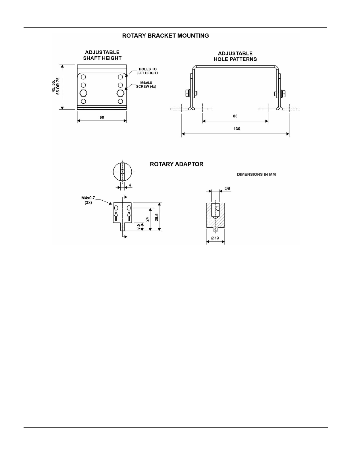
The FY500 can be mounted in any orientation. The mounting parts kit for the quarter turn actuator
contains a mounting bracket with NAMUR VDI/VDE 3845 (DIN EN ISO 5211) standard mounting
patterns. See figure 1.2 for the different quarter turn rotary actuator sizes.

Section 1 - Installation
1.3
Figure 1.2 –Quarter turn actuator sizes
WARNING
In case of a pneumatic or electrical failure, it is important to know the behavior of the
actuator. Before mounting the positioner on an actuator, the failsafe position and
direction of rotation of the actuator drive shaft should be verified.
WARNING
Before starting any assembly or disassembly of the actuator/positioner set, the electrical
supply and pneumatic supply must be removed. The actuator line must also be emptied.
Stay away from moving parts to avoid serious injury.
1. Visually check to make sure the valve is on the fail-safe position. The normal performance of the
quarter turn rotary actuators is clockwise-to-close and counterclockwise-to-open. However, this may
be inverted under request.
2. Position the rotary actuator to its approximately mid-travel position, using a handwheel or manual
loading regulator.
3. The rotary mounting bracket consists of three parts, which can be adjusted to the actuator by
different arrangements. Determine the configuration of the rotary bracket, according to dimensions a
specific actuator size, using four M5 screws, four lock washers, and four flat washers. as shown in
figure 1.3.
TIP
For ease of assembly, attach the L-shaped parts of the mounting bracket only after
installing/screwing the rotary adapter.
FY500 HART –Operation, Maintenance, and Installation Manual
1.4
Figure 1.3 –Rotary mounting bracket configuration
4. Before attaching the mounting bracket, determine the orientation of the FY500. It is ‘’IN-LINE’’ to
actuator mounting when the pneumatic connections are in the same direction as the longitudinal
drive axis of the actuator, or ‘’ACROSS” to actuator mounting when the pneumatic connections are
perpendicular direction as the longitudinal drive axis of the actuator.
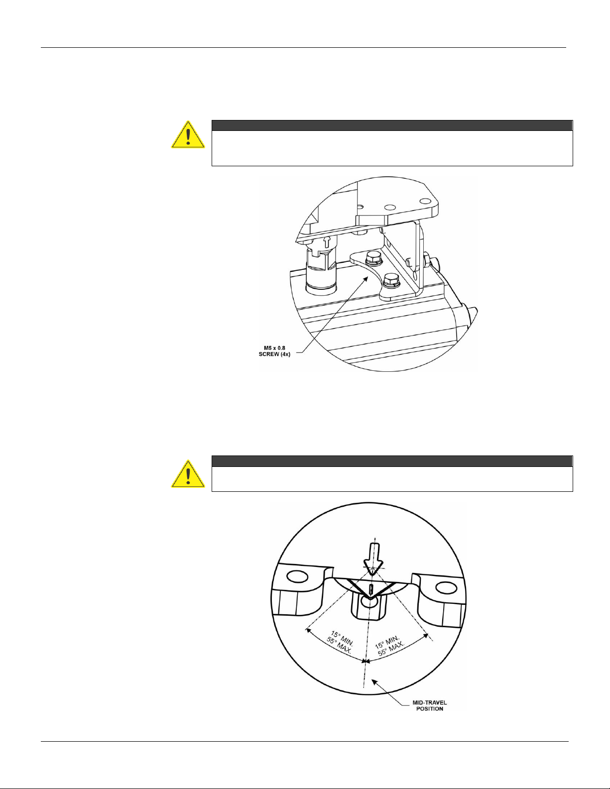
5. Position the FY500 on the actuator mounting bracket and secure in place with four M6 x 1 bolts.
See figure 1.4.

Section 1 - Installation
1.5
Figure 1.4 –Positioner assembly orientation relative to actuator axis
6. Fit the rotary adaptor onto the feedback shaft of the FY500 and adjust its position on the actuator
shaft so that the arrow on the actuator lines up with the arrow mark on the back of the FY500
housing. See figure 1.5.
7. Attach the rotary adaptor to the feedback shaft with one M6 x 10 screw, as shown in figure 1.5.
Tighten until the screw fully enters the part.
Figure 1.5 –Rotary adaptor assembly orientation on actuator
8. Install the L-shaped parts of the mounting bracket to the FY500, using M6 screws, if not already
in place.
9. Install the mounting bracket on the actuator with four M5 x 0.8 screws and flat washers. See
figure 1.6. When attaching the FY500 rotary adaptor to the actuator shaft, ensure that the center pin
FY500 HART –Operation, Maintenance, and Installation Manual
1.6
is fully inserted into the actuator shaft and that the mounting bracket conforms to the configuration
shown in figure 1.3.
10. Tighten the mounting bracket screws securely, both those that make it up and those that secure
it to the actuator.
WARNING
After installation on the rotary actuator, check that the positioner feedback shaft, adapter
and actuator shaft are all aligned. This will avoid friction and other mechanical stresses
not designed for parts, increasing their useful life.
Figure 1.6 –Positioner quarter turn rotary actuator mounting
11. With the actuator at its mid-travel position, the travel indicator is aligned with mark arrow of the
housing .
12. Stroke the actuator to each end of its travel. Travel indicator must travel within the admissible
range, as shown in figure 1.7.
WARNING
When test cycling the actuator and valve assembly by applying pressure to the
pneumatic port, be aware that there are moving parts can cause serious injuries.
Figure 1.7 –Admissible range –rotary mounting bracket
Section 1 - Installation
1.7
Linear Actuator
The FY500 can be mounted in any orientation. The mounting parts kit for the linear actuator
contains a mounting bracket with NAMUR/IEC 60534-6-1 standard mounting patterns. Applicable to
actuators with cast yoke (with rib or plane surface design), or pillar yoke for U-bolt application.
WARNING
In case of a pneumatic or electrical failure, it is important to know the behavior of the
actuator. Before mounting the positioner on an actuator, the failsafe position and
direction of rotation of the actuator drive shaft should be verified.
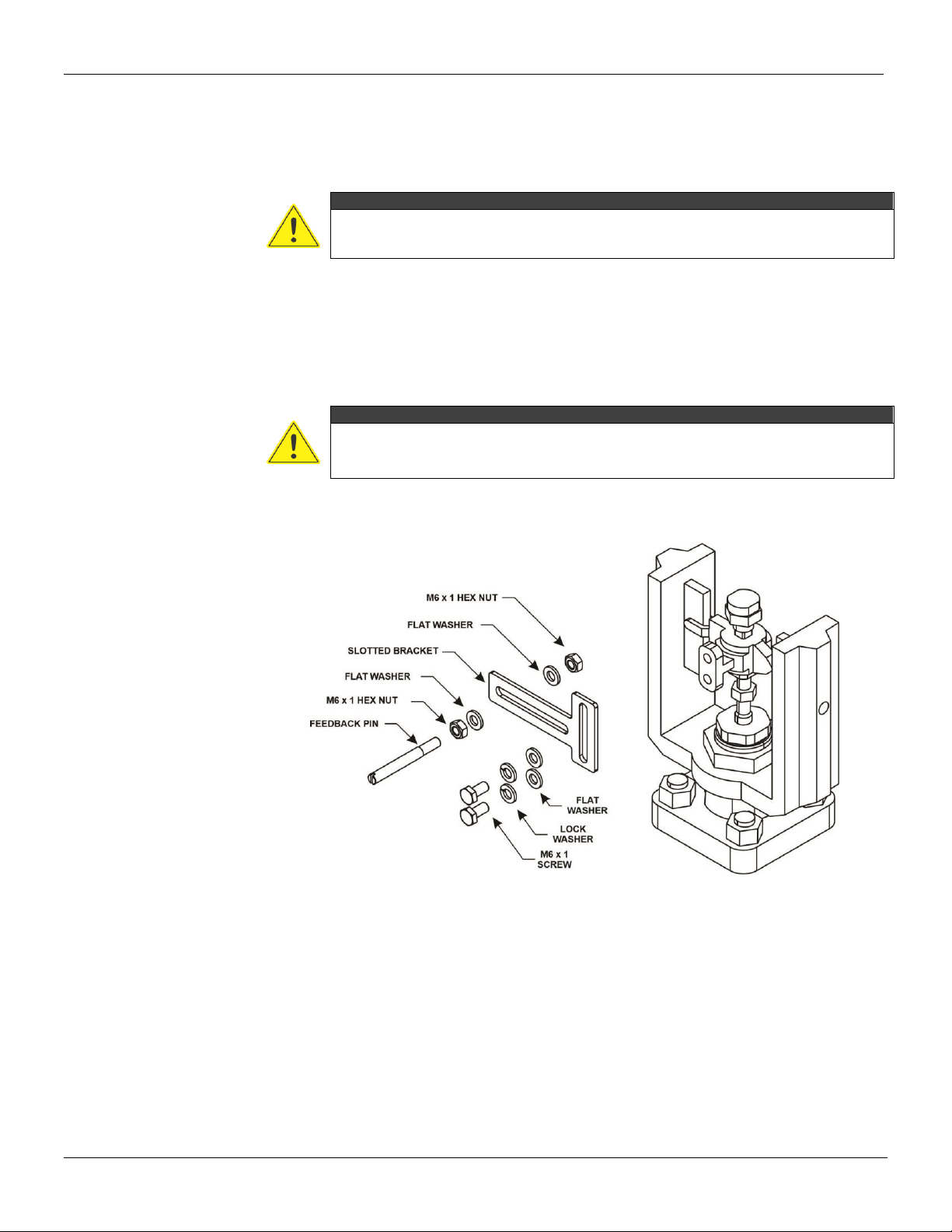
The connection between the actuator stem and feedback arm is typically made using a slotted
bracket and a feedback pin. There are two ways to transfer the motion through the feedback pin, the
traditional mounting method, and the alternate mounting method.
The Traditional Method
The feedback pin is fixed in the slotted bracket and rides inside the feedback arm.
WARNING
Before starting any assembly or disassembly of the actuator/positioner set, the electrical
supply and pneumatic supply must be removed. The actuator line must also be emptied.
Stay away from moving parts to avoid serious injury.
1. Attach the feedback pin to the slotted bracket with two M6x1 hex nuts, and two flat washers.
Leave the hex nut loose for later adjustment. See figure 1.8.
Figure 1.8 –Feedback assembly mounted on actuator stem
2. Attach slotted bracket to the actuator stem with two M6x1 screws, two lock washers, and two flat
washers, but do not tighten the fasteners because fine adjustment is required. See figure 1.8.
3. If required, a mounting adaptor is included in the mounting kit. Attach the mounting adaptor to the
actuator stem so that the mounting adaptor extends through the yoke leg, then attach the slotted
bracket to the adaptor, as shown in figure 1.9. The feedback pin must be on the opposite side of the
stem.

FY500 HART –Operation, Maintenance, and Installation Manual
1.8
Figure 1.9 –Feedback assembly mounted on mounting adaptor
WARNING
In some cases, attach the slotted bracket to the actuactor stem may not be possible,
and an mounting adaptor to actuator stem is required. This adaptor will be shipped to
the customers according to their purchase order.
4. The FY500 mounts on linear actuators with up to 200 mm (8 inch) travel. Refer to figure 1.10 for
the different travel feedback arm sizes depending upon travel of actuator be used.
Figure 1.10 –Feedback arm sizes
Section 1 - Installation
1.9
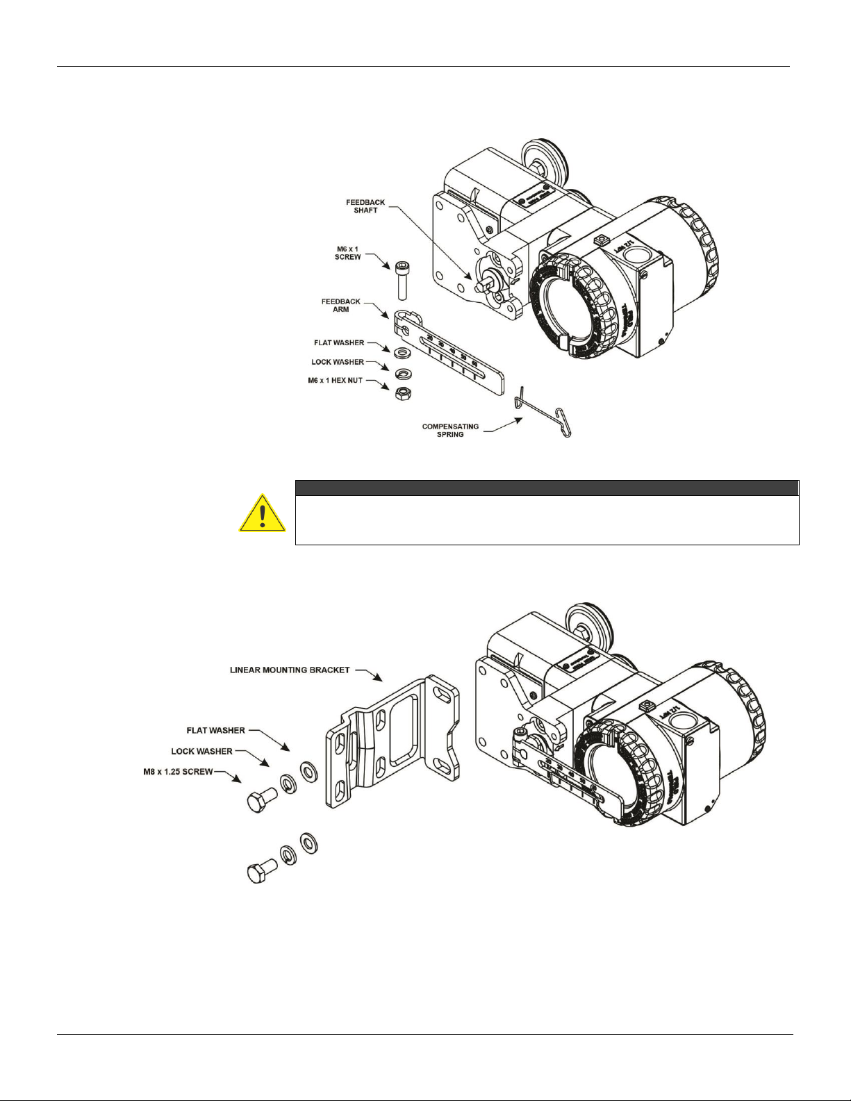
5. Attach the feedback arm to the end of the feedback shaft with M6x1 screw, M6 hex nuts, lock
washers, and flat washers. The markings on the feedback arm must be visible to the
operator/installer. Install the compensating spring on the feedback arm. See figure 1.11.
Figure 1.11 –Feedback arm assembly
WARNING
The compensating spring is used to hold the feedback pin securely against one side of
the feedback arm slot. This prevents excessive play in the linkage and limits the amount
of error introduced into the system through the linkage.
6. Refer to figure 1.12. Mount the positioner to the mounting bracket using two M8x1.25 screws, two
lock washers, and two flat washers.
Figure 1.12 –Positioner mounting bracket
7. Position the actuator to its mid-travel position using a handwheel or manual loading regulator.
8. Adjust the vertical position of the slotted bracket so that the feedback arm and oblong arm are
horizontally aligned. The feedback pin must be in the mark on the feedback arm that indicates the
valve stroke size (see marking on cast yoke). Tighten the M6x1 screws.
9. Before installing the mounting bracket to the actuator yoke, slip the round end of the feedback pin
into the feedback arm slot. Make sure the feedback pin engages the slot in the feedback arm.
FY500 HART –Operation, Maintenance, and Installation Manual
1.10
Secure the mounting bracket to the actuator yoke using the follow procedures:
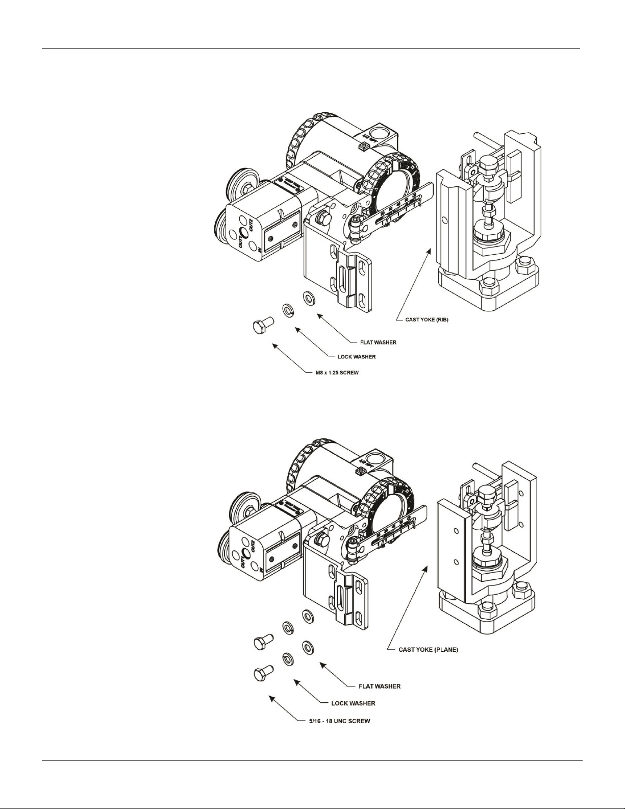
- For actuators with cast yoke with rib surface application, using the M8x1.25 screw, lock
washer, and flat washer. See figure 1.13.
Figure 1.13 –Attachment to cast yoke with rib surface
- For actuators with cast yoke with plane suface application, using two 5/16 –18 UNC
screws, two lock washers, and two flat washers. See figure 1.14.
Figure 1.14 –Attachment to cast yoke with plane surface
Section 1 - Installation
1.11
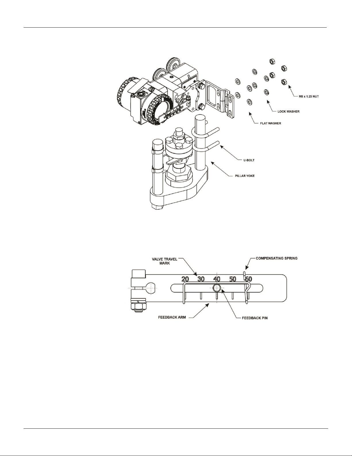
- For actuator with pillar yoke for U-bolt application, using two U-bolt, four lock washers,
and four flat washers, as shown in figure 1.15.
Figure 1.15 –Attachment to pillar yoke for U-bolt
10. Slide the adjustment feedback pin in the slot of the slotted bracket until the pin is in line with the
desired actuator travel marking on the feedback arm. The compensating spring must be
positioned such that the feedback pin sits in the central side of the compensating spring´s slide
area. Tighten the hex nuts. As shown in figure 1.16.
Figure 1.16 –Positioning feedback pin in feedback arm
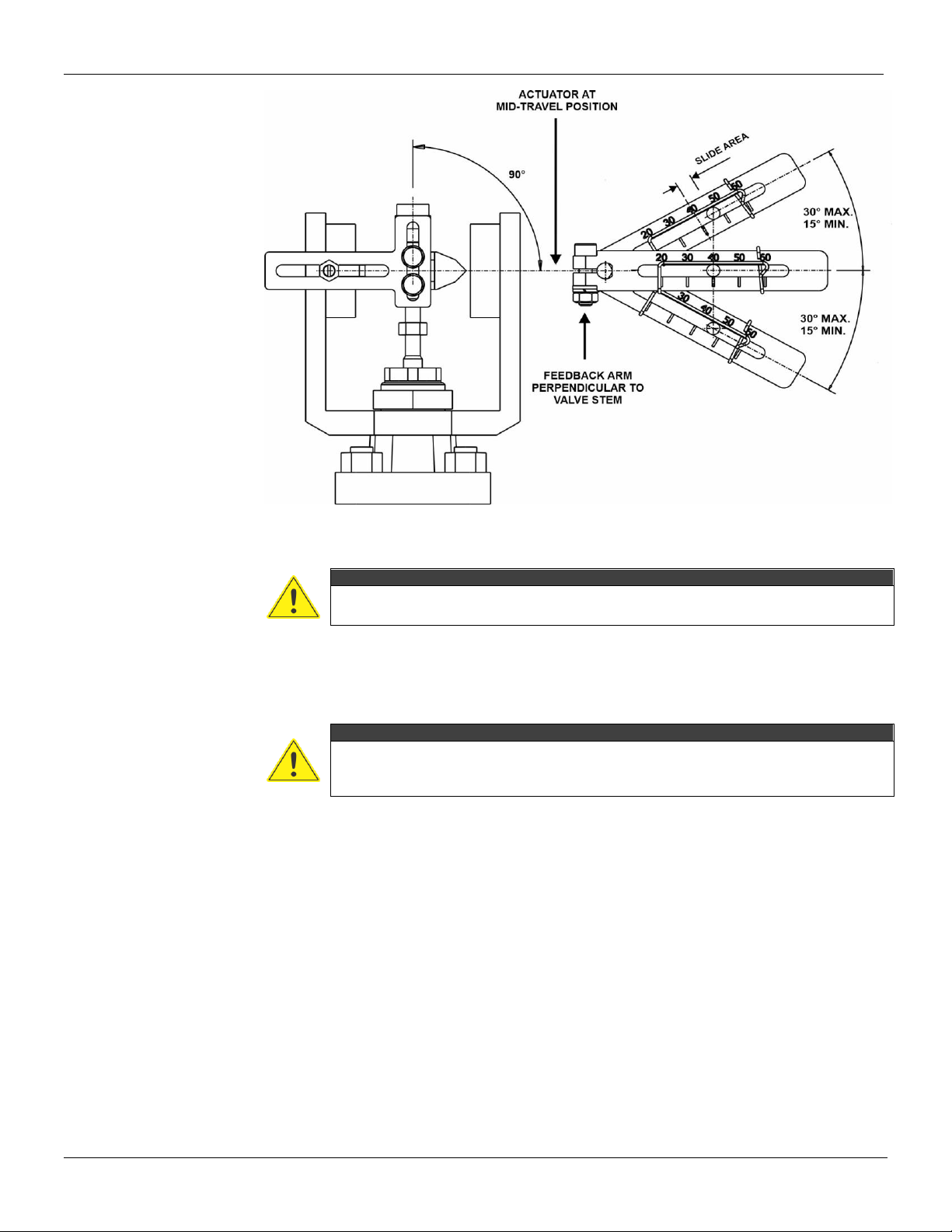
11. With the actuator at its mid- travel position, adjust the mounting bracket location vertically so
that the feedback arm is perpendicular to the stem, as shown in figure 1.17.
12. Stroke the actuator from the top stop to the bottom stop. Travel indicator must travel within the
admissible range. See figure 1.17.
FY500 HART –Operation, Maintenance, and Installation Manual
1.12
Figure 1.17 –Admissible range –linear mounting bracket
WARNING
When test cycling the actuator and valve assembly by applying pressure to the
pneumatic port, be aware that there are moving parts can cause serious injuries.
The Alternate Method
The feedback pin is fixed in the feedback arm and have it ride freely inside the slotted bracket.
WARNING
Before starting any assembly or disassembly of the actuator/positioner set, the electrical
supply and pneumatic supply must be removed. The actuator line must also be emptied.
Stay away from moving parts to avoid serious injury.
1. Install the compensating spring on the slotted bracket.
2. Attach the feedback pin to the feedback arm with two M6x1 hex nuts, and two flat washers.
Adjust the position of the feeback pin so that the center aligns with the appropriate travel mark on
the feedback arm.
3. Complete the assembly procedure described in The Traditional Method topic of this manual.
Section 1 - Installation
1.13
Pneumatic Connections
The FY500 requires instrument air quality, following the best practices for pneumatic installations.
Consult the American National Standard “Quality Standard for Instrument Air”(ANSI/ISA S7.0.01 –
1996) for detailed information. Instrument air shall the following characteristics:
Dew point
10ºC below minimum instrument temperature.
Size of particles
40 µm (maximum).
Oil content
1 ppm w/w (maximum).
Contaminants
Free of corrosive contaminants and hazardous gases.
The instrument air quality shall be superior to that of industrial compressed air. Humidity, suspended
particles and oil contamination, even lubricating oil, may impair the instrument operation, either
temporarily or permanently in case of internal parts wearing.
The mentioned standard recommends to place the compressor intake in an environment free from
process spills, contaminants, and to use adequate filters. Also, the compressors must be of non-
lubricated type to prevent the present of lubrificants. When using lubricated compressors, the plant
must have resources to remove the lubricant from the instrument air supplied.
The supply pressure varies from 2 bar (30 psi) minimum, to 10.3 bar (150 psi) maximum. The
FY500 requires sufficient supply pressure to stroke the actuator to each end of its travel.
Maximum allowable air supply pressure to the positioner must not exceed 10.3 bar (150 psi). For
actuator pressure refer to the appropriate actuator instruction manual.
WARNING
•Never exceed maximum supply pressure. Injury personnel or damage to the
equipment may result.
•Supply pressure to positioner should not exceed actuator maximum pressure rating.
•Blow out all piping before connections are made to prevent dirt, chips, or debris to
entering to the positioner.
•Use a pipe sealant sparingly and only on male threads. It is not recommended a
sealing tape on pneumatic connections.
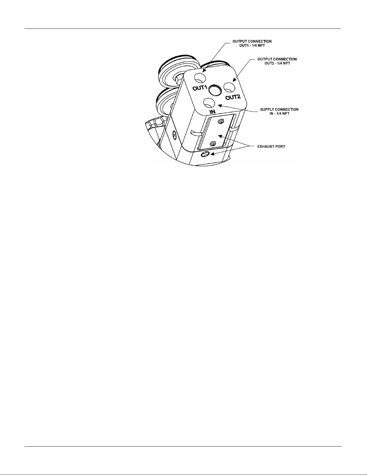
The positioner vents the supply medium into the surrounding atmosphere through holes located in
the positioner vent cover, as shown in figure 1.18. The positioner does not have an external vent
connection. Do not restrict the vent opening. Restricting the vent opening can produce a pressure
buildup in the positioner valve spool and degrade positioner performance. Ensure that the housing
vent opening is open and free of debris to prevent pressure buildup under the cover.
Connect the power supply to the 1/4 NPT IN connection on the positioner. The output connections
1/4 NPT OUT1 and OUT2 must be connected to the actuator. For best response times use tubing of
3/8- inch minimum size. See figure 1.18.
WARNING
When the input current is removed, the FY500 OUT1 should drop to zero and OUT2
register full pressure.
When using a positioner on a single acting actuator, close OUT2 and connect OUT1 to the actuator
pneumatic input.
When using a positioner on a double acting actuator, connect OUT1 and OUT2 to the appropriate
actuator pneumatic input. When the input current is removed, the FY500 OUT1 should drop to zero
and OUT2 register full pressure.
FY500 HART –Operation, Maintenance, and Installation Manual
1.14
Figure 1.18 –Pneumatic connections
Table of contents
Other SMAR Valve Positioner manuals


Popular Valve Positioner manuals by other brands


Bray
Bray 6A series Advanced setup guide

Parker
Parker 404XE Series product manual

Topworx
Topworx PD200 quick start guide

Baker Hughes
Baker Hughes Masoneilan 4700E instruction manual

Emerson
Emerson Fisher 3660 instruction manual

Avid Technology
Avid Technology SmartCal Series Installation and operating instructions

Flowserve
Flowserve XL90 Series Installation, operation & maintenance instructions

Winradio
Winradio WR-ARP-ELAZ-100 Technical user guide

Spirax Sarco
Spirax Sarco SP200 Installation and maintenance instructions

Lincoln Electric
Lincoln Electric POSIMATIC PS30 Safety instruction for use and maintenance

Zimmer
Zimmer MK series Assembly instructions

Courion
Courion iLEARN System manual