Page 10 253273 R3
Section 3 Periodic Maintenance
Periodic Maintenance
For proper operation and an extended service life, your
Lift Tek Mast should be inspected and serviced regularly
as part of your normal lift truck maintenance schedule accord-
ing to the following outlines and ANSI B56.1 procedures.
The recommended intervals are for masts operating under
normal conditions. If the mast is operating in severe conditions
or corrosive atmospheres, the inspections should be per-
formed more frequently.
WARNING: Never work on the mast with a load
on the forks or attachment, in the raised position
without supports or while anyone is near the lift
truck control handles per ANSI B56.1
Daily Inspection
Perform the following at the beginning of each work shift:
1. Extend the carriage a few inches off the ground and make
sure the chains are under equal tension. Refer to Section
5.6-3 for chain adjustment.
2. Extend the mast to its fullest height to make sure the mast rails
and carriage extend freely without binding.
3. While the mast is extended, inspect the upright rails for
proper lubrication. Refer to Section 2.4-3 for rail
lubrication.
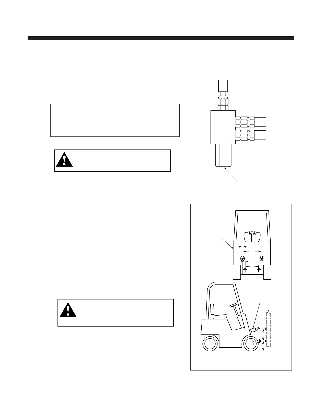
4. Make sure the internal reeving hoses (if equipped) travel
evenly in the hose guides. Adjust the hose ends if re-
quired. Tighten the fittings making sure they do not twist.
5.In applications with high humidity or condensation, chain
lubrication as described under Item 1 of the 100 hour
inspection may be needed more frequently to reduce the
risk of corrosion.
100 Hour Inspection
After each 100 hours of lift truck operation, and in addition to
the daily inspection:
1. Inspect and lubricate the full length of the chains with SAE
40 wt. oil or equivalent.
CAUTION: The chains must be coated with a film of lubricant
at all times.
500 Hour Inspection
After each 500 hours of lift truck operation, and in addition to
the Daily and 100 Hour Inspection:
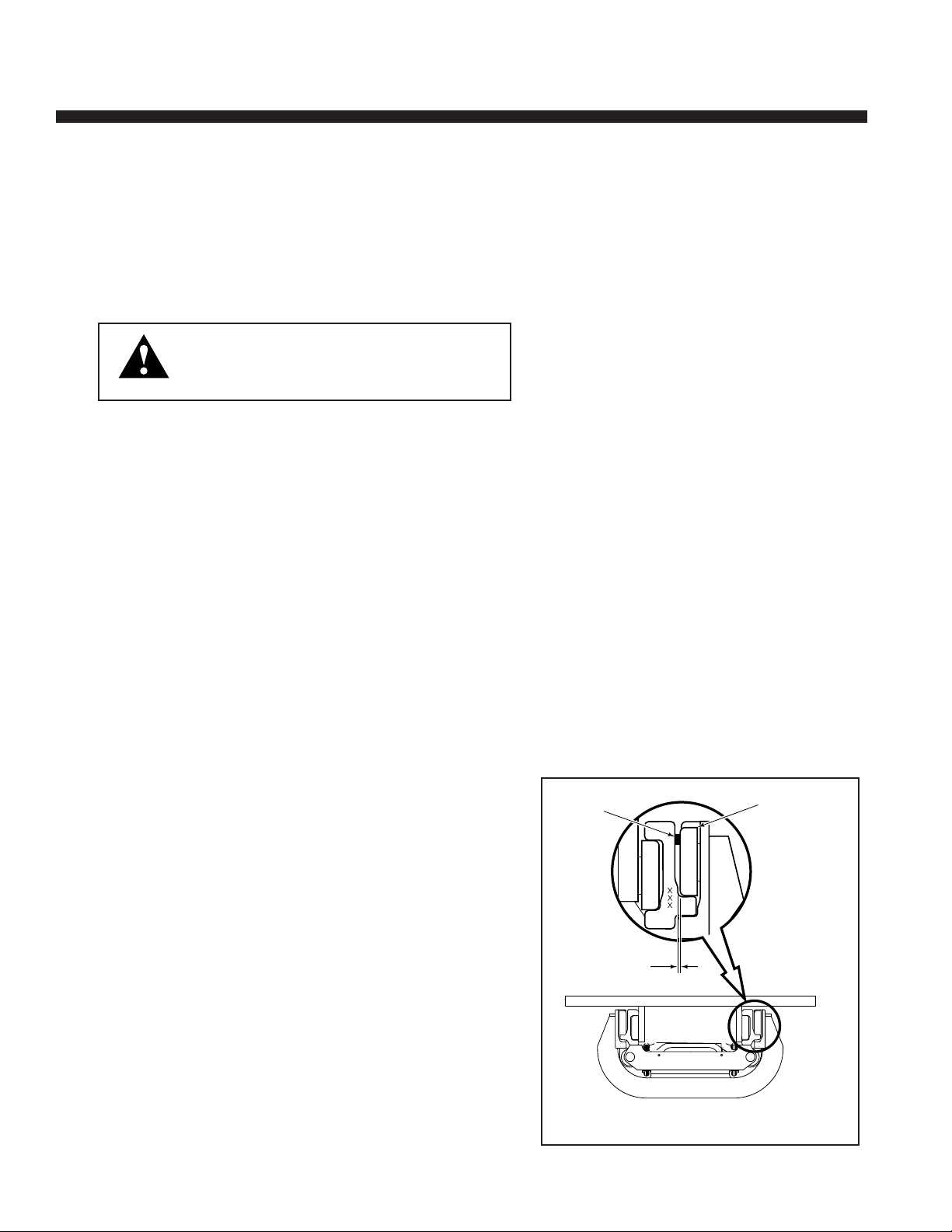
1. Each pair of load rollers on the uprights and carriage
should be shimmed so that a total side to side clearance
no greater than 1/16 in. (1.5 mm) occurs at the tightest
point throughout the travel of the member. Pry between
the upright and load roller so that the opposite load roller
is tight against the upright. Measure the clearance for the
pair of rollers at XXX shown. See Figure 8.
2. Check the chains for wear and stretch. Refer to Section
5.6-1 for complete chain inspection.
3.1
3.1-1
MA2705.eps
Pry Here Load Rollers
.06 in.
(1.5 mm)
MAX.
Figure 8. Load Roller Clearances.