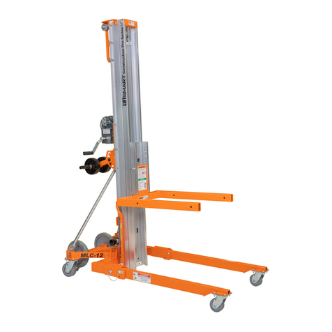
LiftSmart MLC Quick start guide

MLC PARTS & SERVICE MANUAL
Part No. M00969C
Printed in the USA

MLC Construction Pro Series
Part Number M00969C
Parts & Service Manual
Copyright © 2022 LiftSmart
MLC CONSTRUCTION PRO SERIES MATERIAL LIFT
It is the responsibility of the user to read, understand and obey all safety rules before attempting to perform
maintenance on this equipment. This includes all rules and instructions set forth by the manufacturer, as well
as any local laws and regulations governing the safe use of this equipment.
It is strongly recommended that only trained and authorized personnel perform maintenance on this material
lift.
This manual is intended to be used in conjunction with the MLC Construction Pro Series Operator’s Manual.
Failure to read, understand, and obey all safety rules in both manuals, and all safety decals/placards
attached to the material lift, may result in serious injury or death.
LiftSmart is dedicated to the continuous improvement of this and all LiftSmart products. Therefore, technical
information contained in this manual is subject to change without notice. Direct any questions regarding
errors or discrepancies in this manual to LiftSmart.
CONTACT US
LiftSmart
1370 Decision Street
Suite A
Vista, CA 92081
Mailing Address:
P.O. Box 4186
Oceanside, CA 92052-4186
Phone/Fax: 800.717.3079
www.liftsmart.NET
marketing@liftsmart.NET
LiftSmart products are protected by US Patent No. 9,388,028 and other patents pending.

MLC Construction Pro Series
Part Number M00969C
Parts & Service Manual
Copyright © 2022 LiftSmart
1
CONTENTS
1 - SAFETY
2
5 - PARTS (continued)
Personal & Maintenance Safety
3
Mast Assembly (I) - First Mast Assembly
36
Mast Assembly (II) - Center Mast Assembly
2 - INSPECTIONS
4
2011 –2012 Models
40
Daily Inspections
4
2013 - Current Models
42
Visual Inspection
5
Mast Assembly (III) - Front Mast & Carriage
Function Test
5
2011 –2012 Models
44
Quarterly Inspections
6
2013 - Current Models
46
Cleaning the Masts
7
Back of the Mast Assembly
48
Inspecting the Winch
7
Winch Assembly
50
Lubricating the Winch
7
Smart-Latch™ Option
52
Annual Inspections
8
CE Mast Brake (Current Models)
54
Inspecting the Mast Assembly
9
CE Mast Brake (First Generation)
56
Inspecting the CE Mast Brake System
10
Standard Fork Assembly
58
Adjustable Fork Assembly
58
3 - TROUBLESHOOTING
12
Boom Assembly
60
Load Platform Accessory
60
4 - REPAIR
14
Pipe Cradle Accessory
62
Removing the Base
15
Fork Extensions Accessory
62
Disassembling the Mast
17
Manual Storage Tube Assembly
62
Assembling the Mast
18
Cable Assemblies
63
Replacing a Pulley
20
Cable Guard Option
64
Replacing a Pulley Mount
21
Retractable Lifting Point Option
64
Replacing the Cable
22
Replacing the Transport Wheel Option
24
APPENDIX A: Machine Specifications
65
Replacing the Hold Down Bar
24
Assembling the Hold Down Bar
24
APPENDIX B: Torque Specifications
67
5 - PARTS
25
APPENDIX C: Inspection Checklist
69
Decals - ANSI
26
Decals - CE
28
Standard Base and Stabilizers
30
Leg Assembly
32
Transport Wheel Assembly
34

MLC Construction Pro Series
Part Number M00969C
Parts & Service Manual
Copyright © 2022 LiftSmart
1. SAFETY
Failure to follow all safety rules in this manual, in addition to the MLC Construction Pro Series Operator’s
Manual, and all safety decals/placards attached to the material lift may result in serious injury or death.
Proper training is strongly recommended before attempting to perform maintenance on any mechanical
device.
Before performing maintenance:
❑Read, understand, and obey all safety rules and instructions in this manual, in addition to the MLC
Construction Pro Series Operator’s Manual,and all safety decals/placards attached to the material lift.
❑Read and understand warning symbols found in this manual and in the workplace.
❑Obtain, read, and obey all applicable government regulations.
❑Become familiar with the proper operation of the material lift.
❑Technicians should receive instruction before performing maintenance on the material lift.

MLC Construction Pro Series
Part Number M00969C
Parts & Service Manual
Copyright © 2022 LiftSmart
3
PERSONAL SAFETY
Safetyand continued safe operationof the material
lift should be your highest priority.
Follow these safety rules while operating or
performing maintenance on the material lift:
ALWAYS:
❑Wear personal protective equipment
(PPE), including protective eyewear,
gloves, and steel-toed shoes.
❑Be aware of potential hazards created by
removing components from the material lift
or by lifting or placing loads.
❑Understand and obey all the safety rules
and warnings found in the workplace.
MAINTENANCE SAFETY
Follow these safety rules while performing
maintenance on the material lift:
ALWAYS:
❑Read each procedure carefully before
beginning maintenance on the material lift.
❑Read, understand, and obey the safety
rules described in the MLC Construction
Pro Operator’s Manual.
❑Choose a work area that is clean, well-lit,
and properly ventilated.
❑Keep sparks and open flames away from
flammable materials such as grease or oil.
❑Tag a damaged material lift and
immediately remove it from service until
repairs are completed according to the
manufacturer’s specifications.
❑Be aware of potential hazards created by
removing components of the material lift
while performing maintenance.
❑Use only the correct tools for the
maintenance procedure.
❑Ensure tools required to perform needed
maintenance are in good working
condition.
Safety alert symbol –used to alert
personnel to potential injury
hazards. Obey all safety messages
that follow this symbol to avoid
possible death or serious injury.
Indicates an imminent hazardous
situation which, if not avoided, will
result in serious injury or death.
Indicates a potentially hazardous
situation which, if not avoided, will
result in serious injury or death.
Indicates a potentially hazardous
situation which, if not avoided, may
cause minor or moderate injury.
Indicates a potentially hazardous
situation which, if not avoided, will
result in machine or property
damage.
Decal/Placard Symbol Legend

Parts & Service Manual
Part Number M00969C
MLC Construction Pro Series
4
Copyright © 2022 LiftSmart
2. INSPECTIONS
Regular inspection of the material lift will ensure that the equipment is operating safely and effectively.
Performing all preventive/predictive maintenance procedures according to the manufacturer’s
recommendations will extend the life of the material lift and help to ensure safe operation for machine
operators.
While inspecting the equipment:
•Perform all daily, quarterly and/or annual
inspections according to the
manufacturer’s recommendations.
•Perform all quarterly and/or annual
preventive/predictive maintenance
procedures according to the
manufacturer’s recommendations.
•Create a record of all inspections and/or
maintenance performed using the
Scheduled Maintenance and Inspection
Checklist provided in the back of this
manual.
DAILY INSPECTIONS
Perform each of the following inspections daily or
before each use of the material lift:
❑Verify that the MLC Construction Pro
Series Operator’s Manual is in the storage
container attached to the material lift. The
pages must be legible and in good
condition.
❑Perform a visual inspection of the material
lift for wear or damage.
❑Perform a function test on the material lift
to verify winch is operating correctly, holds
a load, and that the Fork Carriage and
masts raise and lower in the correct
sequence.

MLC Construction Pro Series
Part Number M00969C
Parts & Service Manual
Copyright © 2022 LiftSmart
5
VISUAL INSPECTION
Perform the following inspections daily or before
each use:
❑Inspect the wheels and casters for excessive
wear or damage.
❑Inspect the material lift for loose, damaged, or
missing fasteners.
❑Inspect the base, legs, stabilizers, masts,
pulleys, and forks for damage and improperly
installed or missing components.
❑Inspect the cable for wear, frays, kinks, or
damage.
❑Verify that the cable is wrapped around the
winch drum at least four times when the Fork
Carriage is fully lowered.
❑Inspect the entire material lift for dents,
damage, excessive rust or corrosion, and
cracks in welds or on structurally critical
components, such as the aluminum masts.
❑Verify that all decals are legible and correctly
attached to the material lift.
WARNING
If any worn or damaged components are
observed or suspected, remove the material lift
from service immediately. Repairs to the
material lift should only be performed by
authorized personnel according to the
manufacturer’s specifications.
FUNCTION TEST
(2-Speed Winch Models)
Perform the following test daily or before each use
to verify that the equipment is not malfunctioning:
❑Shift the winch to the low speed.
❑Firmly grasp both winch handles.
❑Rotate the winch handles toward the mast to
raise the Fork Carriage to its full height.
The winch should operate smoothly without
hesitation or binding. The motion should raise the
Fork Carriage to the top of the Front Mast followed
in order by each adjacent mast.
❑Rotate the winch handles away from the mast
to completely lower the telescopic mast
assembly.
❑Rotate the winch handles one quarter-turn
toward the mast - as if raisingthe Fork Carriage
- to set the brake
The winch should operate smoothly without
hesitation or binding. Shift the winch to the high
speed and repeat steps above to complete test.
Notice: The handle rotations listed above are
opposite for models equipped with the 1-Speed
Winch.
WARNING
If the equipment malfunctions, remove the
material lift from service immediately. Repairs
to the material lift should only be performed by
authorized personnel according to the
manufacturer’s specifications.

Parts & Service Manual
Part Number M00969C
MLC Construction Pro Series
6
Copyright © 2022 LiftSmart
QUARTERLY INSPECTIONS
Perform the following inspections quarterly or after every 100 hours of operation. Perform these inspections
in addition to all daily inspections:
NOTE:It is important to perform all the inspections listed to ensure the material lift can be used correctly and
safely. Failure to perform the inspections listed may result in injury or death.
❑Visually inspect the welds for cracks, excessive wear, or corrosion.
❑Inspect the welds on:
▪Fork and other load lifting attachment(s)
▪Base
▪Legs
▪Stabilizers
▪Transport Wheel Option (if equipped)
▪Winch mounting plate
▪Smart-Set adjustment system
❑Clean the masts.
❑Inspect the winch.
❑Lubricate the winch.

MLC Construction Pro Series
Part Number M00969C
Parts & Service Manual
Copyright © 2022 LiftSmart
7
CLEANING THE MASTS
LiftSmart requires that this procedure be performed
every 200 hours or quarterly, whichever comes
first.
Perform the following steps to clean the masts:
❑Raise the material lift to its maximum height.
❑Visually inspect the inner and outer roller wheel
channels of each mast for foreign material or
debris.
❑As needed, clean the channels of each mast
using a mild cleansing agent.
When cleaning the masts, NEVER:
❑Lubricate the masts.
❑Apply an additional side load orhorizontal force
to a material lift that is loaded and/or raised.
❑Place ladders or scaffold against the material
lift.
INSPECTING THE WINCH
(Refer to winch diagram in Section 5 - Parts)
❑Raise the Fork Carriage halfway to ensure the
winch is operating correctly.
Result: The winch should operate smoothly.
❑Lower the Fork Carriage.
Result: The winch should operate smoothly.
If winch is not operating properly, perform the
following inspections on the winch:
❑Inspect the brake lining plates for excessive
wear.
▪Replace the brake lining plate if it is less
than 1/16 inch (1.5 mm) thick.
❑Inspect the reamed bushings on the shaft for
excessive wear.
▪Replace the reamed bushing if the wall
thickness is less than 1/8 inch (3.1 mm).
❑Inspect the winch assembly for loose,
damaged, or missing fasteners.
▪Tighten or replace fasteners as needed.
▪Tighten the 3/8-16 lock nut that attaches
the reel assembly to 20 ft-lb (27 N*m).
▪Do not over tighten fasteners.
LUBRICATING THE WINCH
Lubricate the gears on the followingcomponents of
the winch using automotive grease:
❑The reel assembly.
❑The ratchet wheel.
❑The primary shaft assembly.
❑The intermediate shaft assembly (2-speed
winch models).
ADDITIONAL WINCH LUBRICATION
Lubricate the following winch components with the
lubricant listed:
❑Lubricate the ratchet pawls with 30W oil.
❑Lubricate the reel spacer with automotive
grease.
Injury hazard. This procedure may
require the use of additional access
equipment. Do not place ladders or
scaffolding against the machine.
Performing this procedure without
the proper skills and tools may
result in serious injury or death.
Dealer service is recommended.

Parts & Service Manual
Part Number M00969C
MLC Construction Pro Series
8
Copyright © 2022 LiftSmart
ANNUAL INSPECTIONS
Lubricate the Casters and Wheels.
Perform the following inspections annually.
Perform these inspections in addition to all daily
and quarterly inspections.
It is important to lubricate casters and/or wheels for
a proper use of the product and to extend its
service life.
❑Inspect the wheels and casters for cracks or
cuts and excessive wear.
❑Lubricate the casters and wheels:
•Using the Zerk fittings, add lithium-based
grease into the bearings of the wheels
and casters until it becomes visible at the
bearing gap.
❑On a level surface, push and steer the
material lift to make sure casters and wheels
roll effortlessly.
Inspect the Painted Surfaces
A visual inspection of the painted areas will assist
in recognizing potentially damaged areas of the
material lift, which will need to be corrected for the
continued safe use of the machine.
❑Visually inspect the painted surfaces of the
material lift for blisters, peeling, rust, fading or
corrosion.
Inspect the Hold Down Bar
Unsafe work areas occur when damage to the MLC
Construction Pro Series is not discovered.
❑Visually inspect the Fork Carriage and Hold
Down Bar.
❑Check if the Hold Down Bar is operating
correctly.
NOTE: The Hold Down Bar is operating correctly
when it does NOT overstroke the top of the Fork
Carriage and when it prevents the telescopic
mast assembly from extending when the mast is
parallel to the ground.
Inspect the Pulleys, and Cable
This inspection should happen at least annually.
Failure to check the sub-components of the
material lift can lead to serious injuries or even
death.
NOTE: Due to visual obstructions the mastmust be
disassembled to properly and fully inspect the mast
rollers, pulleys, and cable.
1. Disassemble the Mast (refer to related
information in Section 4 of this manual).
2. Inspect the Cable, Pulleys, and related sub-
components and look for the following issues:
▪Kink(s) in the cable.
▪Broken wires.
▪Corrosion.
▪Cracks in the swaged cable end.
▪Damaged pulleys and pulley mounts.
▪Mounting plates are firmly secured.
3. Inspect Mast Rollers (refer to related
information in Section 4 of this manual).
NOTE: If something abnormal or damage is
located during the inspection, remove the
Material Lift from the workplace immediately.
4. Re-assemble the Mast (refer to related
information in Section 4 of this manual).

MLC Construction Pro Series
Part Number M00969C
Parts & Service Manual
Copyright © 2022 LiftSmart
9
INSPECTING THE MAST
ASSEMBLY
Perform the following steps to inspect the mast
assembly for wear:
❑Engage hold-down barand then tilt the material
lift back and lower it onto a support so that the
masts are parallel to the ground and the Fork
Carriage is facing up.
❑At the top of the material lift, measure the
clearance between each roller wheel on each
mast and the surface of the adjacent mast with
a feeler gauge.
▪If the clearance between the roller wheel(s)
and the adjacent mast is greater than 0.062
inches (1.57 mm), then replace the roller
wheel(s).
▪Refer to Section 4 - Repair for instructions
to disassemble the mast assembly.
❑At the base of the material lift, measure the
clearance between each roller wheel on each
mast and surface of the adjacent mast with a
feeler gauge.
▪If the clearance between the roller wheel(s)
and the adjacent mast is greater than 0.062
inches (1.57 mm), then replace the roller
wheel(s).
▪Refer to Section 4 - Repair for instructions
to disassemble the mast assembly.
Above is a feeler gauge, also known as a
thickness gauge.

Parts & Service Manual
Part Number M00969C
MLC Construction Pro Series
10
Copyright © 2022 LiftSmart
Inspecting The CE Mast Brake System
(When equipped)
Material lifts exported outside of the Americas are
typically equipped with a mast braking system to
comply with local regulations (regulations may vary
depending on the geographic area).
NOTES:
•If the mast does not sequence properly, the
mast brake may be activated.
•To disengage the mast brake, raise the mast
using the winch approximately 6 - 8 inches
(15.2 - 20.3 cm) until it disengages.
•This process needs to be performed by two
(2) or more technicians.
1. Using the winch, raise the Fork and Carriage
to the halfway point of the mast.
2. Using a wooden plank such as a 2 x 4 or 4 x
4 stud, with one person holding each end,
place the plank under the Fork Carriage and
lift it approximately 6 - 8 inches (15.2 - 20.3
cm), then quickly release the plank out from
under the Fork Carriage.
RESULT: The Fork Carriage should stop
within 5 inches (12.7 cm) and the mast brake
should be engaged.
3. Using the winch, disengage the mast brake
by raising the Fork Carriage approximately 6
- 8 inches (15.2 - 20.3 cm).
4. Raise the Fork Carriage to full height and
then the Front Mast halfway up the adjacent
Center or First Mast (depending on model).
5. Place the plank under the Front Mast and lift
it approximately 6 - 8 inches (15.2 - 20.3 cm),
then quickly release the plank out from under
the Front Mast.
RESULT: The mast should stop within 5
inches (12.7 cm) and the mast brake should
be engaged.
6. Using the winch, raise the Front Mast
approximately 6 - 8 inches (15.2 - 20.3 cm)
and the mast brake will disengage.
7. Lower the Front Mast all the way down.
8. For models consisting of 3 or more
telescopic stages: At the top of the material
lift, use a jaw lockingplier (commonly referred
to under the trade name Vice-Grip®) to pinch
the Front Mast and adjacent Center Mast
tightly together.
9. Raise the Fork Carriage to full height and
then raise the combined Front Mast and
adjacent Center Mast halfway up the next
adjacent Center Mast (or First Mast
depending on machine model).
10. Place the plank under the combined Front
and Center Mast and lift it approximately 6 - 8
inches (15.2 - 20.3 cm), then quickly release
the plank out from under the Fork Carriage.
RESULT: The combined mast should stop
within 5 inches (12.7 cm) and the mast brake
should be engaged.
11. Using the winch, raise the mast
approximately 6 - 8 inches (15.2 - 20.3 cm)
and the mast brake will disengage.
12. Fully lower the combined Front and Center
Mast.
NOTES: The procedure above uses jaw-locking
pliers to isolate the individual mast brake being
tested. Therefore, jaw locking pliers should remain
attached and a new one added for each successive
center mast being tested, this will require multiple
jaw-locking pliers for mast assemblies consisting of
4 or more telescopic stages.
Sometimes, to disengage the mast brake,
additional jaw locking pliers will be needed to grab
the column behind that of the one being tested.
The First Mast (sometimes referred to as Mast A),
attached to the base, does not need to be tested
because it does notcontain a mast brake and does
not elevate.
Injury hazard. Failure to recognize
a damaged mast with mast brake
may result in serious injury or
death.
* Please check our website (liftsmart.NET) for upcoming
videos that will demonstrate this testing procedure.

MLC Construction Pro Series
Part Number M00969C
Parts & Service Manual
Copyright © 2022 LiftSmart
11
This page left intentionally blank.

Parts & Service Manual
Part Number M00969C
MLC Construction Pro Series
12
Copyright © 2022 LiftSmart
3. TROUBLESHOOTING
When the material lift malfunctions, use the chart on the following page to help determine the root cause and
to correct the issue.
To use the troubleshooting table, locate the specific symptom in the first column. Possible causes of the
malfunction are listed in the second column in descending order beginning with the most probable issue first.
To correct the issue(s), perform the procedure listed in the third column, using the information provided in
Section 4 - Repair and Section 5 - Parts as needed.
***DISCLAIMER***
The troubleshootingtable in this manual providesa list ofthe mostprobable malfunction that may occurbefore,
during, or after operating the material lift, however, additional issues not outlined in the troubleshooting table
may arise before, during, or after operating the material lift. Contact LiftSmart for additional assistance as
needed.
When troubleshooting the material lift:
❑Follow all the safety rules provided in previous sections of this manual and in the MLC Construction Pro
Series Operator’s Manual and all safety decals/placards attached to the material lift.
❑Use the table on the following page to determine the cause of the malfunction and the solution to correct
the issue(s).
❑Use Sections 4 & 5 of this manual, as needed, to repair the issue to correct the malfunction.

MLC Construction Pro Series
Part Number M00969C
Parts & Service Manual
Copyright © 2022 LiftSmart
13
COMPLAINT
Possible CAUSE
CORRECTION
Mast does not sequence properly.
The material lift is at or above
maximum capacity.
Remove excess weight from the
load.
A pulley-mount is broken.
Inspect and replace all broken pulley
mounts.
The load is not properly centered.
Center the load.
Excessive debris in the masts or
pulleys.
Clean the masts and pulleys.
The cable is binding on the pulleys.
Inspect the pulleys and cable;
replace as needed.
The roller wheels are damaged.
Or
The roller wheels are not properly
lubricated.
Inspect the roller wheels; replace or
lubricate roller wheel bolts as needed
with multi-purpose grease.
One or more masts are damaged.
Inspect the masts; replace as
needed.
Winch operates, but the Fork
Carriage will not raise.
The winch drum is not rotating inside
the winch.
Inspect the winch; repair or replace
as needed.
The cable is damaged or broken.
Inspect the cable for frays, kinks, or
other damage; replace as needed.
One or more pulleys are damaged.
Inspect the pulleys; repair or replace
as needed.
The cable is not correctly routed
through the pulleys.
Remove the cable; install the cable,
carefully route it correctly through the
pulleys.
Winch will not operate.
The material lift is at or above
maximum capacity.
Remove excess weight from the
load.
Cable is not wound onto the winch
drum properly.
Lower and remove any load then re-
spool cable onto winch drum.
The load is not properly centered.
Center the load.
The load is obstructed.
Clear the obstruction or reposition
the material lift.
The cable is binding at the winch or
inside the material lift.
Remove the cable.
Inspect the cable for frays, kinks, or
other damage; replace as needed.
The winch is damaged.
Inspect the winch; repair or replace
the damaged component(s) or entire
winch as needed.
One or more masts are damaged.
Inspect the masts; repair or replace
as needed.

Parts & Service Manual
Part Number M00969C
MLC Construction Pro Series
14
Copyright © 2022 LiftSmart
4. REPAIR
The following section provides instructions for the safe and proper repair of the material lift. It is the
responsibility of only a trained and authorized technician(s) to follow these instructions. Failure to follow these
instructions, as well as all safety rules in this manual, and all decals/placards attached to the material lift, may
result in serious injury or death.
Procedures in this section for disassembling components should be performed onlyuntil the necessaryrepairs
can be completed. Follow the steps of the disassemblyprocedure in reverse order to re-assemble the material
lift.
While performing repairs:
❑Follow all the safety rules provided in previous sections of this manual and in the MLC Construction Pro
Series Operator’s Manual,and all safety decals/placards attached to the material lift.
❑Follow all instructions provided in this section.
❑Ensureonlythe proper tools and parts are used to performand make the necessary repairson the material
lift.
❑For safety, before making any repair, the machine should be on a level surface, Fork Carriage down, Hold
Down Bar engaged, and Casters locked.

MLC Construction Pro Series
Part Number M00969C
Parts & Service Manual
Copyright © 2022 LiftSmart
15
REMOVING THE BASE
Follow this procedure to remove the base from the
material lift and refer to the related parts diagrams
in Section 5 for replacement parts.
NOTE: If removing the base to replace the First
Mast (M00437), follow the procedures below to
remove the cable from the winch drum prior to
tilting the lift back, to allow the mast to be fully
disassembled.
❑Loosen the hex nut on the Fork Carriage bolt
that attaches the cable clamp (M00834) to the
reel (drum) on the winch assembly.
❑Remove the cable from the reel (drum) on the
winch assembly.
Follow this procedure if only removing the base
from the material lift (and not servicing the mast
assembly):
❑Fully lower the Fork Carriage.
❑Remove the load lifting attachment from the
material lift and engage the hold down bar.
If the lift is equipped with stabilizers (M00070):
❑Remove the cap screws from the Stabilizer
Latch Mounting Bracket (M00075) on the First
Mast.
❑Remove the cap screw that attaches each
Stabilizer Weldment (M00071) to the base.
❑Remove the Stabilizer Assembly.
❑Leave the Push Tube Weldment (M00106) in
the 90-degree position, relative to the First
Mast.
❑Tilt the material lift back and lower it onto a
support so that the leg casters are not touching
the ground.
❑Remove the ball detent pin (M00088) and
guide each leg to its storage position.
❑Remove the cap screw that attaches each leg
to the base.
❑Remove the legs.
❑Tilt the material lift forward to an upright
position.
❑Using a shop crane to assist and/or between
two to three (2 - 3) technicians, firmly grasp the
material lift and place it parallel to the ground
on a firm structure such as a set of metal
sawhorses, positioning the material lift with the
Fork Carriage facing down.
WARNING: Failure to ensure the material lift is
placed parallel to the ground on a firm structure
may result in serious injury or death.
❑Remove the cap screws that attach the Left
and Right Struts (M00024 & M00025) to the
base.
❑If replacing a Strut, remove the cap screw
connecting the Strut to the Winch Mount
Weldment (M00101) and replace.
❑If the Base Weldment isbeing removed to allow
access to replace the First Mast then fully
remove both Struts.
❑While removing the Base Weldment, note if
there are spacer washers compressed in
between the First Mast and the Base
Weldment (M00014) and reuse them in the
same position when re-assembling.
NOTE: When re-assembling or replacing the Base
Weldment (M00014) to the First Mast follow the

Parts & Service Manual
Part Number M00969C
MLC Construction Pro Series
16
Copyright © 2022 LiftSmart
procedure above in the reverse sequence with the
added steps below:
Prior to tightening the cap screws to the Base
Weldment and Struts ensure the right and left side
of the Base Weldment is square (set to 90-
degrees) with the First Mast (use a square). Also
note that each model of material lift has a slight
rearward tilt back angle built in to ensure the
telescopic mast is perpendicular when elevated to
full height at full rated load. Refer to specifications
table below for the acceptable tilt-back range for
each model. On a known level surface, use a
digital inclinometer to verify that the tilt-back of the
mast is within the recommended range listed
below:
Model
Tilt Back Range
MLC-12
1⁰ to 1.5⁰
MLC-18
1.5⁰ to 2⁰
MLC-24
1.8⁰ to 2.25⁰
This column left intentionally blank.

MLC Construction Pro Series
Part Number M00969C
Parts & Service Manual
Copyright © 2022 LiftSmart
17
DISASSEMBLING THE MAST
Follow this procedure to disassemble the mast
(refer to prior section if base is also to be removed):
NOTE: Removal of the Base Weldment is only
necessary when the First Mast is to be repaired.
The material lift should be placed on a firm
structure with the Fork Carriage facing up.
NOTE: Any material lift equipped with a mast brake
needs to be disassembled slowly to prevent the
brake from engaging.
❑Completely unspool, but do not remove, the
cable from the reel (drum) on the winch
assembly.
❑Fold the stabilizers (if equipped) into their
stowed positions.
❑Remove Fork and engage Hold Down Bar.
❑Using a shop crane to assist and/or between
two to three (2 - 3) technicians, tilt the material
lift backwardsand place itparallel to the ground
on a firm structure (such as metal sawhorses)
so the Leg Assemblies are not touching the
ground.
Note: If there is no firm structure or metal
sawhorses available, the machine can be
positioned on its back with the Push Tube
Weldment placed in the second highest
position, so that the machine is resting on the
rear of the base (or transport wheels if
equipped) and the wheels on the Push Tube
Weldment (M00106). In this case, the Push
Tube Wheels should be placed on a pallet or
two stacked pallets (or other similar firm
structure acting as a spacer) to ensure the
mast is parallel to the ground. THE MAST
MUST BE PARRALLEL TO GROUND.
Removal of the Left and Right Struts will be
necessary if using sawhorse.
❑If desired, for easier access, the Leg
Assemblies can be folded into their stowed
position by a.) removing the Ball Detent Pin
from each Leg Assembly and b.) fully folding
the Legs Assemblies and inserting the Ball
Detent Pin into the leg stowage position.
❑Disengage Hold Down Bar.
Note: Prior to disengaging the Hold Down Bar
ensure the mast is parallel to the ground to avoid a
potential safety hazard and to prevent the mast
from inadvertently spreading apart.
❑Slide the Fork Carriage forward along the mast
to expose the Down Stop (M00062).
❑Remove the flat head screw that attaches the
Down Stop to the mast.
❑Remove the Fork Carriage from the mast.
❑After removing the Fork Carriage, repeat this
procedure to remove each mast:
▪Slide the mast forward to expose the Down
Stop on the adjacent mast.
▪Remove the cap screw that attaches the
Down Stop to the adjacent mast.
▪Remove the Down Stop.
▪Slide the mast back and out of the bottom
of the adjacent mast.
Note: For convenience and efficiency (if not
replacing the entire cable), the procedure above
allows the Mast to be disassembled with the cable
still attached throughout each telescopic mast
stage. If desired the cable can be removed prior to
disassembling the mast by disconnecting it from
the winch reel (drum) in step one and then pulling
it out of the mast assembly from the Cable End
Weldment (M00065).

Parts & Service Manual
Part Number M00969C
MLC Construction Pro Series
18
Copyright © 2022 LiftSmart
ASSEMBLING THE MAST
Follow this procedure to assemble a mast that has
been disassembled:
If the Base Weldment has not been removed the
Left and Right Struts must be removed to allow the
machine to be safely positioned on a set of metal
sawhorse or other firm structure.
NOTE: Blue Loctite® (or equivalent) MUST be
applied on Down Stop (M00062) fasteners.
NOTE: Ensure the mast brake is installed (if the
material lift does not have a mast brake, omit this
step).
NOTE: Masts with a braking system should be
assembled slowly to prevent the brake from
engaging.
❑Inspect the masts including all components,
fasteners, and cable for wear or damage.
Replace as needed.
❑Clean the masts, rollers, and all roller channels
using a mild cleansing agent.
NOTE: Do NOT use wet lubricants in the mast. A
dry wax-type lubricant such as Boelube® can be
applied inside the roller channels, but not required.
❑If the First Mast or Base Weldment has been
replaced, position it with open side up on a firm
structure (such as metal sawhorses) so that it
is parallel to the ground. Secure the First Mast
onto the firm structure with channel locks or
other locking devices or methods.
❑If the First Mast or Base Weldment has not
been replaced, the machine should already be
in the parallel position and ready for re-
assembly following the completion of the prior
disassembly procedure.
❑Attach all components, including the rollers, to
the First Mast, Center Masts, and Front Mast
(as needed). At this time, it is recommended
that all pulley bolts are sealed with red Loctite®
and torqued to specifications (refer to torque
chart contained in this manual) and all Pulley
Mount (M00054) mounting bolts have been
securely tightened and that Blue Loctite® has
been applied to the bolt threads.
❑Slide the Center or Front Mast (depending on
model) into the First Mast from the bottom until
the mast up stop on the second mast is even
with the bottom of the First Mast.
❑Repeat the previous step for each mast that
was included in the telescopic mast assembly.
Each mast should be sticking out slightly from
the adjacent mast below. Do not attach the
Fork Carriage.
❑If previously removed or replaced, attach the
swaged end of the cable to the Cable End
Weldment anchor (M00065) at the top of the
Front Mast.
❑Feed the other end ofthe cable through the box
section of the Fork Carriage (M00040 or
M00240) and into the pulley.
❑Push the cable through the pulleyuntil it comes
back out of the Fork Carriage.
❑Slide the Fork Carriage into the bottom of the
Front Mast.
❑Hold the Fork Carriage in place and pull the
cable along the length of the Front Mast to the
top, leaving enough slack to feed the cable into
the pulleys.
❑Feed the cable into the exposed pulley at the
top of the Front Mast until it reaches the pulley
at the bottom of the Front Mast.
❑Use needle nose pliers to route the cable into
the pulley at the bottom of the Front Mast until
it reaches the top of the mast.
❑Route the cable into the pulley at the top of the
next adjacent mast until it reaches the pulley at
the bottom of that mast.
❑Repeat this process to feed the cable through
the pulleys at the top and bottom of each mast
until the cable is threaded out of the top of the
First Mast.
Table of contents
Other LiftSmart Lifting System manuals
Popular Lifting System manuals by other brands

Suspa
Suspa MOVOTEC Series manual

Draper
Draper AeroLift 25 Installation & operating instructions

Faraone
Faraone ELEVAH 61 Translation of the original instructions

Power Tower
Power Tower Nano SP Plus Operating and maintenance manual

JLG
JLG LiftPod FS80 Operation, Safety, Service and Maintenance Manual

weha
weha SLAB GRAB JUMBO II Operation and service instructions

Novoferm
Novoferm NovoDock L320 Translation of the original assembly instruction

Tiger
Tiger CSS Original instruction guide

PSS
PSS RightPath BoardWalk Assembly instructions

Faraone
Faraone E5P100 Use and maintenance instructions

SAMES KREMLIN
SAMES KREMLIN 102 415 0001 manual

Rotary
Rotary SL212i 400 Series Operation & maintenance manual