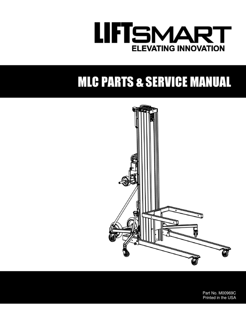
LiftSmart MLM Mini-Pro Series User manual

Operator’s Manual Part Number M00972A MLM Mini-Pro Series
2 Copyright © 2012 LiftSmart
BEFORE OPERATION
Follow these safety rules before operating
the material lift:
ALWAYS position the material lift on a firm,
level surface.
ALWAYS inspect
the work area for
potential hazards
such as overhead
obstructions,
unstable or slippery
surfaces, drop-offs,
holes, debris or
moving vehicles.
ALWAYS inspect the equipment before
operating the material lift. Check for
damaged or worn parts. NEVER operate a
material lift if any damage to the equipment
is observed or suspected. ALWAYS tag a
damaged material lift and remove it from
service until repairs are completed
according to manufacturer’s specifications.
ALWAYS inspect the winch and cable
before operating the material lift. Check for
wear, frays, kinks and damage to the cable.
Verify that the cable is wrapped around the
winch drum at least four times when the
carriage is lowered. NEVER operate a
material lift if any damage to the winch or
cable is observed or suspected.
NEVER repair the material lift in any way
other than according to manufacturer’s
specifications.
NEVER deface, modify or obscure any
decals or markings on the material lift.
NEVER modify the material lift in any way
that would affect its original design or
operation.
NEVER operate the material lift in any way
for which it is not intended.
DURING OPERATION
Follow these safety rules while operating
the material lift:
NEVER operate the material lift near power
lines. ALWAYS ensure that no part of the
material lift can accidentally reach into an
unsafe area.
DANGER
The material lift is NOT insulated for use
near electrical power lines and DOES
NOT provide protection from contact
with or proximity to any electrical
current. Maintain safe distances at all
times (minimum 3.05 meters; see chart
below). Allow for mast movement or
electrical line sway due to environmental
conditions. ALWAYS assume every
power line is live.
Voltage Range
(Phase to Phase)
Minimum Safe Approach Distance
Feet Meters
0 to 300V Avoid Contact
Over 300V to 50KV 10 3.05
Over 50KV to 200KV 15 4.60
Over 200KV to 350KV 20 6.10
Over 350KV to 500KV 25 7.62
Over 500KV to 750KV 35 10.67
Over 750KV to 1000KV 45 13.72
ALWAYS keep away
from a material lift
that is exposed to
energized power
lines. If the material
lift contacts energized
power lines, NEVER
touch or operate the
machine until power
lines are shut off.

MLM Mini-Pro Series Part Number M00972A Operator’s Manual
Copyright © 2012 LiftSmart 3
NEVER use the
material lift to
raise or lower
persons.
NEVER stand or
climb on the
material lift.
NEVER operate the material lift unless the
legs and stabilizers are fully lowered and
locked and all casters are in contact with
the ground.
NEVER unlock or raise the legs or
stabilizers while the material lift is loaded or
raised.
ALWAYS keep hands and fingers away
from potential pinch and shear points, such
as folding legs and stabilizers, mast
sections, and as indicated by decals
attached to the material lift.
NEVER operate the equipment unless the
material lift is located on a firm, level
surface.
NEVER use blocks to level the material lift.
ALWAYS center the load on the load lifting
attachment and secure the load before
operating the material lift.
NEVER stand
under the material
lift when the load is
raised. NEVER
lower the material
lift unless the area
below is clear of
personnel and
obstructions.
NEVER operate
the material lift on
a moving or
mobile surface,
such as a truck
bed.
NEVER exceed the rated load capacity of
the material lift.
NEVER move a material lift with a raised
load.
NEVER touch or grab the cable.
NEVER operate
the material lift
when exposed to
high winds,
thunderstorms or
other weather
conditions that
could compromise
the safety of the
operator.
NEVER apply an additional side load or
horizontal force to a material lift that is
loaded or raised. NEVER place ladders or
scaffold against the material lift.
NEVER use the material lift as a ground for
welding.
NEVER leave the material lift unattended
while a load is raised.

Operator’s Manual Part Number M00972A MLM Mini-Pro Series
6 Copyright © 2012 LiftSmart
8
1
2
3
4
5
6
7
8
9
COMPONENTS
Become familiar with the major components
of the material lift. Familiarity with the
components identified on the diagrams
below is necessary to ensure safe and
proper operation of the material lift.
1 Mast Sections
2 Forks (Shown in Up/Inverted Position)
3 Carriage
4 Legs
5 Two-speed Winch
6 Smart-Set Adjustment System
7 Carriage Hold-down Bar
8 Casters
9 Loading Wheels

Operator’s Manual Part Number M00972A MLM Mini-Pro Series
14 Copyright © 2012 LiftSmart
VISUAL INSPECTION
Before operating the material lift:
Inspect the wheels and casters for
excessive wear or damage
Inspect the material lift for loose,
damaged or missing fasteners
Inspect the base, legs, stabilizers, mast
sections, pulleys and forks for damage
and improperly installed or missing
components
Inspect the cable for wear, frays, kinks
or damage
Verify that the cable is wrapped around
the winch drum at least four times when
the carriage is lowered
Inspect the entire material lift for dents,
damage, excessive rust or corrosion
and cracks in welds or on structurally
critical components, such as mast
sections
Verify that all decals are legible and
correctly attached to the material lift
WARNING
If any worn or damaged components are
observed or suspected, remove the
material lift from service immediately.
Repairs to the material lift should only
be performed by authorized personnel
according to the manufacturer’s
specifications.

MLM Mini-Pro Series Part Number M00972A Operator’s Manual
Copyright © 2012 LiftSmart 15
SET UP
To set up the machine, select an area
that is firm, level and clear of debris and
overhead obstructions.
Follow these steps to set up the
machine:
If the material lift is equipped with
stabilizers:
Push down on the stabilizer lock
plates to release the stabilizers
Lower the
stabilizers until
the casters are
in contact with
the ground
Verify that the
lock plates are
engaged and the stabilizers are
locked in the down position
Remove the leg retainer pin
Lower the leg to the down position
Insert the leg retainer pin through the
leg and the base
Repeat the above steps to lower and
secure the other leg
Place the desired load lifting attachment
(standard forks, adjustable forks, boom)
inside the carriage
Insert the fork retainer pin through the
load lifting attachment and the carriage
Engage the locking toggle on the fork
retainer pin
Rotate the carriage hold-down bar up
and away from the carriage
If the material lift is equipped with
adjustable forks:
Pull up on the snap pins
Adjust the forks to the desired
width
Verify that the snap pins are
properly inserted
To install fork extensions:
Slide the extension tube onto the
fork
Adjust the extension tubes to the
desired position
Insert the retaining pins through the
extension tube and the fork
If the material lift is equipped with a load
platform:
Place the load platform on the forks

Operator’s Manual Part Number M00972A MLM Mini-Pro Series
16 Copyright © 2012 LiftSmart
FUNCTION TEST
After the material lift is set up, perform the
following test to verify that the equipment is
not malfunctioning:
Shift the winch to the slow speed
Firmly grasp both winch handles
Rotate the winch handles toward the
mast to raise the carriage to its full
height
The winch should operate smoothly, without
hesitation or binding, and the motion should
raise the carriage to the top of the first mast
section followed in order by each
consecutive mast section.
Rotate the winch handles away from the
mast to completely lower the carriage
Rotate the winch handles one quarter-
turn toward the mast - as if raising the
carriage - to set the brake
UP
DOWN
The winch should operate smoothly, without
hesitation or binding.
WARNING
If the equipment malfunctions, remove
the material lift from service
immediately. Repairs to the material lift
should only be performed by authorized
personnel according to the
manufacturer’s specifications.
WORK AREA INSPECTION
NEVER set up the material lift where any of
the following hazards exist:
Drop-offs
Holes
Debris
Uneven or unstable surfaces
Surfaces that will not support the forces
imposed by the material lift, its operation
and its load.
Slippery surfaces
Slopes
Overhead obstructions
Power lines or other electrical
conductors
High winds or inclement weather
Moving vehicles
ALWAYS position the material lift on a firm,
level surface.

MLM Mini-Pro Series Part Number M00972A Operator’s Manual
Copyright © 2012 LiftSmart 19
POSITIONING THE LOAD
Determine the following before placing a
load on the material lift:
Weight of the load
Location of the load center
Distance between the load center and
the side of the load that will be closest to
the carriage
LOAD
LOAD
CENTER
DISTANCE
THIS SIDE
TOWARD
CARRIAGE
NOTE: Load center refers to the center of
gravity of the load and may not be its
physical center. The heaviest side of an
uneven load should always be positioned
closest to the carriage on the material lift.
Refer to the chart below to determine if the
material lift can lift the desired weight.
MODEL
Load Center
14 in
36 cm
24 in
61 cm
42 in
107 cm
MLM-12 700 lb
318 kg
440 lb
200 kg
185 lb
94 kg
MLM-16 650 lb
295 kg
430 lb
195 kg
175 lb
80 kg
MLM-20 600 lb
272 kg
400 lb
181 kg
200 lb
91 kg
WARNING
Raising a load that exceeds the rated lift
capacity of the material lift creates a tip-
over hazard, which may result in serious
injury or death.
Place the load on the load lifting
attachment
LOAD
CENTER
DISTANCE
The load should be as close to the
carriage as possible, and the load
center should be centered between the
forks
WARNING
Raising a load that is not properly
centered on the material lift creates a
tip-over hazard, which may result in
serious injury or death.
Secure the load to the load lifting
attachment
WARNING
Raising a load that is not securely
fastened to the load lifting attachment
creates a tip-over hazard, which may
result in serious injury or death.

Operator’s Manual Part Number M00972A MLM Mini-Pro Series
20 Copyright © 2012 LiftSmart
TWO-SPEED SHIFT
To change the winch speed, push the
winch handles sideways in the direction
of the desired speed
ÍSLOW ySPEED yFASTÎ
Push the winch handles to the left to
shift the winch to the slow speed
Push the winch handles to the right to
shift the winch to the fast speed
Turn the winch handles toward the mast
until the winch locks
RAISING AND LOWERING THE LOAD
Set up the material lift and position the
load according to the procedures on the
previous pages
Verify that the load is secured to the
load lifting attachment
Shift the winch to the desired speed
Firmly grasp both winch handles
Rotate the winch handles toward the
mast to raise the load
Rotate the winch handles away from the
mast to lower the load
UP
DOWN
After lowering the load to the desired
position, rotate the winch handles one
quarter-turn toward the mast - as if
raising the carriage - to set the brake
AFTER USE
Reverse the set up procedure to prepare
the material lift for storage.
Store the material lift on a firm, level
surface that is protected from the weather,
dirt and other hazards that could reduce the
lifespan of the equipment.
This manual suits for next models
3
Table of contents
Other LiftSmart Lifting System manuals
Popular Lifting System manuals by other brands

GUIL
GUIL TORO D-404 Operator's manual

HOMECARE PRODUCTS
HOMECARE PRODUCTS EZ-ACCESS TILT Toilet Incline Lift Corded... Installation and user manual

HADEF
HADEF 147/05 Installation, Operating and Maintenance Instruction

Sinoboom
Sinoboom GTJZ0408SE parts manual

rav
rav RAV518T manual

AGI
AGI M42 Assembly, Operation and Maintenance Manual