INSTALLATION INSTRUCTIONS
For Flex II 300 Watt Magnetic Transformer - Wall
_________________tel.800-670-8137 www. lightwavesconcept .com
Light Waves
LED Waves
Light Waves
Lighting SuperStore
_________________tel.800-670-8137 www. lightwavesconcept .com
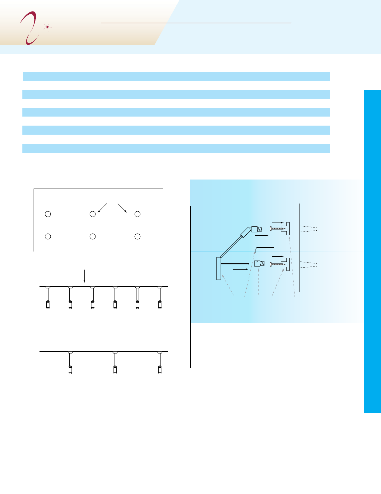
SAVE THESE INSTRUCTIONS AND REFER TO THEM WHEN ADDITIONS
TO OR CHANGES IN THE TRACK CONFIGURATION ARE MADE.
_________________tel.800-670-8137 www. lightwavesconcept .com
Trobleshooting
Did the breaker on the transformer trip?
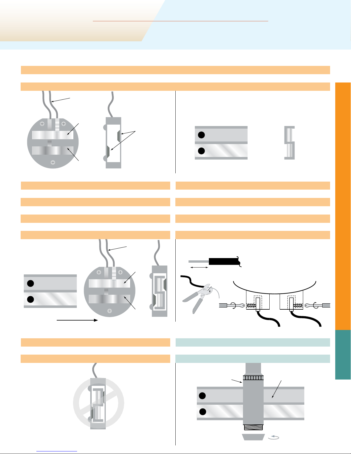
• If powering the system with more than one feed, make sure isolating connectors are separating each feed
• Check that none of the elements are generating a direct short. If any elements have been shortened, check the FreeJack connector
• Check the low-voltage side of the transformer with a voltmeter to ensure voltage does not exceed 12 or 24 volts
Is an individual element not working?
• Check that the lamp is installed securely
• Check the lamp to see if it has burned out
• Check the FreeJack connector for proper contact
Did the breaker on the main panel trip?
• Make sure the circuit has not been overloaded
• Change the breaker in the panel to an inductive load breaker
Is the system still not working? Why not try checking the basics?
• Check the light switch (or cord switch on a plug-in transformer)
• Make sure the power feeds from the transformer to the rail are tightly connected
• Check for loose wire nuts in the junction box, canopy, or transformer cover
• Make sure the transformer’s 120 volt side is wired correctly
Dimming Issues
• There are two kinds of low voltage dimmers. If you wish to attach a dimmer to your Flex II system, make sure to use the correct ver-
sion: a magnetic dimmer should only be used with a magnetic transofrmer. Likewise, an electronic dimmer should only be used with
an electronic transformer. Using the wrong dimmer will substantially shorten transformer life.
• The dimmer should be placed on the input line BEFORE the transformer.
Reducing Dimmer Noise
Dimmers can generate a buzzing noise that some people may nd disturbing. To reduce buzzing, we recommend:
• using the dimmer type compatible with the transformer;
• adding debuzzing dimmer coil in series. This coil is included with all our magnetic surface transformers;
• Loading the system to at least 80 % of capacity. For example, a 300 watt transformer should have at least 240 watt load.
&5--JTUFE
53"$,
-*()5*/(
4:45&.
$POGPSNTUP6-4UE
&5-5&45*/(-"#03"503*&4*OD