manuals.online logo
Brands
  1. Home
  2. •
  3. Brands
  4. •
  5. Lightforce
  6. •
  7. Automobile Accessories
  8. •
  9. Lightforce DL150LED User manual

Lightforce DL150LED User manual

1
USER
INSTRUCTIONS
(with positioning light functions)
TRIPLE SWITCHING HIGH POWERED
HARNESS FOR GENESIS AND VENOM
LED LIGHTS
2USER INSTRUCTIONS LIGHTFORCE.COM
DIY HARNESS INSTALLATION KIT
CONTENTS
• 1 x Driving light harness
• 1 x HB3 patch harness
• 1 x H4 patch harness
• 1 x Switch loom (dual switches)
• 1 x Screw for relay installation
• 2 x T-taps for wires (2 sizes)
• 4 x Spade terminals (2 sizes)
• 15 x Cable ties
• 1 x User instructions.
TOOLS AND CONSUMABLES REQUIRED
• Spanner
• Pointy nose pliers
• Wire cutters
• Phillips head driver bit
• Flashlight (recommended)
• Torque wrench (recommended).
TOOL REQUIRED FOR
NON-STANDARD INSTALLATIONS
• Crimping tool.
PERSONAL SAFETY WARNING
WARNING: High intensity light source.
Do not look directly into the light during operation,
eye injury may result.
Visit lightforce.com/installations to view
instructional videos.
NOTE: If you are using a different switch with
dash illumination (not included), a Lightforce
Switch Adaptor (not included, see Figure 9) will
be required. Follow the instructions included with
the Lightforce Switch Adaptor. The yellow dash
illumination cable (item 10 in gure 1) will need to
be wired to the dash light / park light.
3
T-taps for wires 3.
Black
Fig 3. Connectors for
non-standard installations
Fig 2. Screw
for xing relay
Insulated male spade terminals
4.
Red
1.
2. 10.
Yellow
9.
5.
Brown
7.
Green
8.
Red
6.
Blue
Fig 4. 8 Pin connector wiring diagram (switches side)
Fig 1. Driving Light Harness
1. 40 Amp Relay
2. Driving light 4 pin connectors
3. Battery negative ring terminal
4. Battery positive ring terminal
5. Ignition pickup wire
6. Low beam pickup wire with bullet
terminal (positive)
7. High beam pickup wire
with bullet terminal (negative)
8. High beam pickup wire
with bullet terminal (positive)
9. Dashboard switch loom connector
10. Dash illumination cable (tment optional).
1. 2.
3.
4.
5.
6.
7.
8.
1 Yellow Dash Illumination (from park lights)
2 Black Negative
3 Blue Switch to Output - to relay trigger
4 Red Switch 2 Input - from high beam positive
5 White Switch 1 Output - driving lights
6 Green Switch 1 Input - from vehicle ignition
7 Not Used N/A
8 Not Used N/A
4USER INSTRUCTIONS LIGHTFORCE.COM
STEP 1. MOUNT THE LIGHTS
1. Locate a suitable mounting position to install the
driving lights.
2. Remove the nyloc nut and M10 washer from
M10 x 35mm bolt attached to the bottom of
mounting bracket
3. Locate the bracket in a suitable position using
the M10 x 35mm bolt. It is recommended that
the base area of the mounting bracket is totally
supported
4. Align the light to preferred driving position
5. Fit the washer and M10 nyloc nut, then tighten
using a 17mm socket and ratchet to specied
torque (35Nm). Do not use rattle guns
6. Tighten 2 x M10 x 35 side bolts to recommended
torque (35Nm).
WIRING HARNESS INSTALLATION
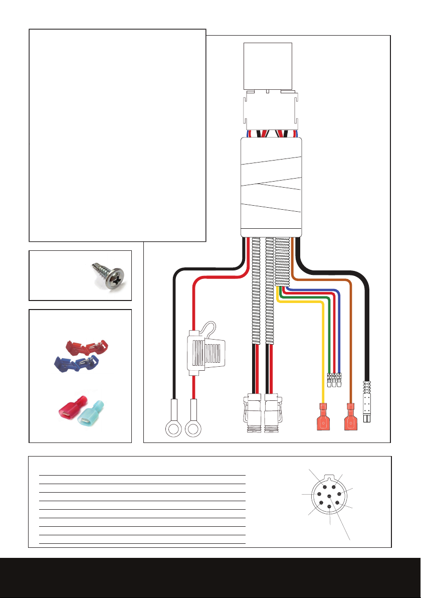
STEP 2. INSTALL THE RELAY AND
CONNECT THE LIGHTS
1. Remove the main ground wire from the negative
battery terminal. WARNING: This may result in
loss of radio security code and clock settings.
Please consult your owner’s manual before
disconnecting
2. Mount the 35 amp relay (see gure 1) in a
suitable place within the engine bay, using the
screw supplied (gure 2) and your drill with
a Phillips head driver bit. Ensure that the red
(positive) and black (negative) ring terminals
reach the appropriate battery terminals.
3. DO NOT CONNECT TERMINALS TO THE
BATTERY AT THIS STAGE
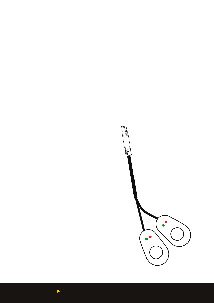
4. Route the insulated sleeved wires that run from
the relay to the driving light connectors to each
of your installed driving lights and connect the
driving light connectors to the back of each light.
Ensure that cables do not touch the radiator or
come in contact with any sharp edges
5. Secure all excess wire to the vehicle with cable
ties supplied. (See Page 6)
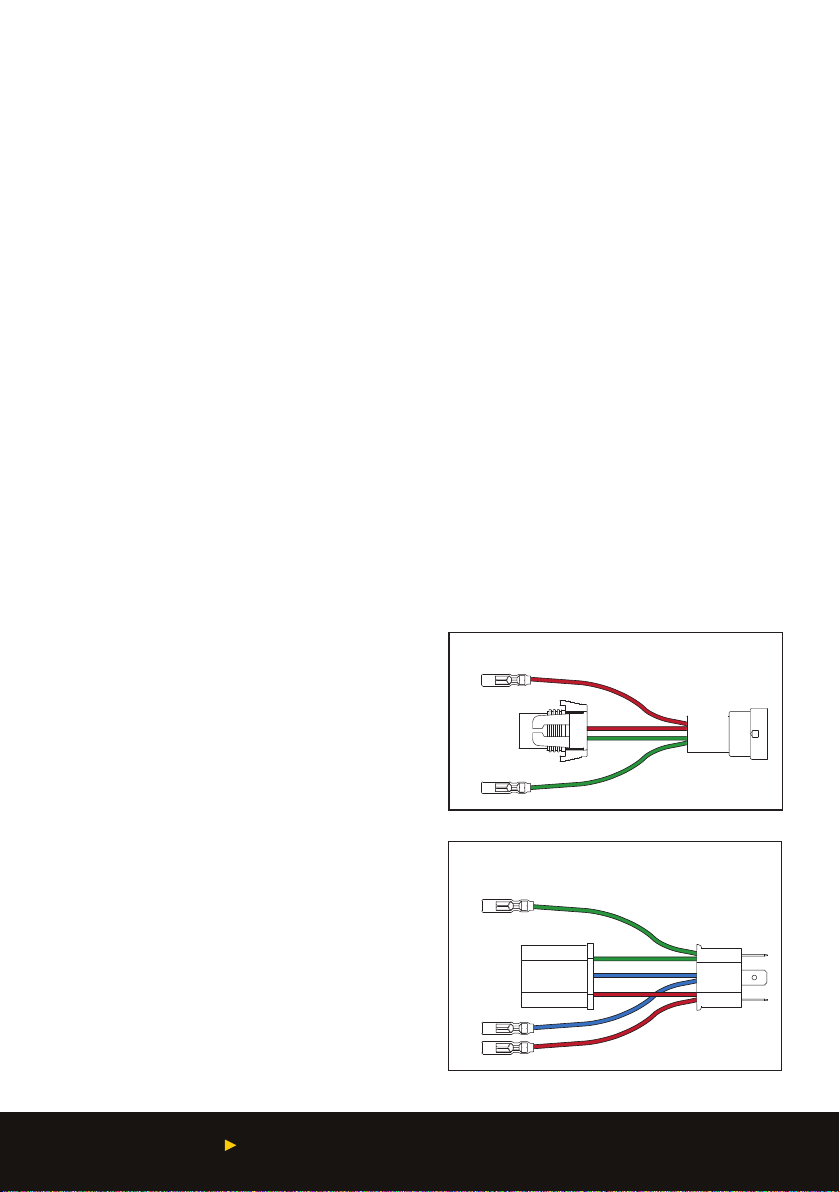
STEP 3. FULL INTENSITY MODE ONLY
1. Select the HB3 or H4 patch harness (refer to
your vehicle’s owner’s manual and gures 5
and 6 below to determine which is correct)
and connect it to a headlight connector on your
vehicle. If your headlights are a type other than
HB3 or H4, see item 3 below.
2. Connect the high beam pickup wires on the
driving light harness to the patch harness, red to
red, green to green.
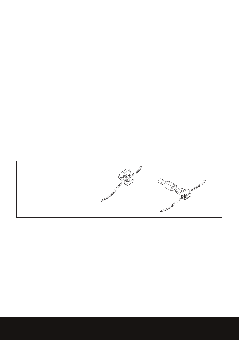
3. NOTE: if you are installing into a vehicle with
headlights that are NOT HB3 or H4, you will
need to remove the bullet terminals on the red
and green high beam pickup wires on the driving
light harness (see gure 1) and crimp each wire
into a blue insulated male spade terminal using a
crimping tool. Then clamp the provided t-taps to
the high beam positive & negative wires on one
of the vehicle’s headlights. Use the red or blue
t-taps depending on the wire diameter. Finally,
connect the blue insulated male spade terminals
into the t-taps on the harness.
Green
Red
Blue
Fig 6. H4 patch harness
Green
Red
Fig 5. HB3 patch harness
Headlight
connector
Headlight
connector
5
OPTIONAL WIRING - POSITIONING
LIGHTS (switch one)
NOTE: This function will enable and disable the
positioning lights .
Refer to gure 1 for wire colours and identication
1. Locate the ignition signal wire in your vehicle
and connect to the spade terminal (#5) brown
wire (refer to gure 1)
NOTE: Ensure the ignition voltage is over 10 volts.
CONNECTING LOW BEAM PICK UP
For H4: Connect the blue wire (No.6) on the H4
path harness to the blue wire on the main harness.
For HB3: Using a multi-meter or test light locate
the Low Beam positive wire located on the back
of the headlight and t the supplied T Tap over the
Low Beam positive wire. Figure 7
Two sizes of T Tap connectors are supplied in
the kit, the purple one suits small gauge wires
0.5-1.0mm2, the blue one is for heavy gauge wires
1.5-2.5mm2.
For HB3 and all other congurations (excluding
H4) cut off the existing bullet terminal on the end
of the blue wire (No.6) on the main harness, strip
5mm of insulation off the end and crimp one of the
supplied red insulated male spade terminals.
Connect the male spade terminal to the T Tap
connector ensuring it is full inserted
Fig 7. T-Tap Connection
6USER INSTRUCTIONS LIGHTFORCE.COM
STEP 4. INSTALL THE DASH SWITCHES
1. Find a suitable place on the dash to mount the
dash switches.
2. Afx dash switches by removing the adhesive
from the rear of the switches and attach to the
desired location.
• Switch 1 is for positioning lights
• Switch 2 is for high beam
STEP 5. CONNECT THE DASHBOARD
SWITCH LOOM
1. Route the dashboard switch loom connector
(on the driving light harness) carefully through
the vehicle’s rewall using pointy nose
pliers to pull the cable through. A ashlight
will help you to see what you are doing.
Be careful to avoid crushing the connector.
Ensure the wires are kept away from any
heat sources
2. Connect the dashboard switch loom connector
on the driving light harness (see item 1, gure
1) to the dashboard switch loom pictured in
Figure 8. Note: The notch on the switch loom
and wiring harness must be aligned.
If you are using a different switch with
dash illumination (not included), connect
the dash illumination cable (on the switch
loom) to your switch, as directed by the user
instructions for the switch.
STEP 6. CONNECT TO THE BATTERY
1. Connect the ring on the red wired battery
connector to the positive battery terminal
using a spanner
2. Connect the ring on the black wired battery
connector to the negative battery terminal
using a spanner.
STEP 7. SECURE CABLES
1. Use the supplied cable ties to secure all loose
cables and remove excess using wire cutters.
STEP 8. TEST
1. With ignition on check the following functions:
• The positioning light function is activating
with the ignition switch, ensure the switch 1 is
in the on position.
• With vehicles low beam switch on check that
the positioning light function dim to become a
night positioning light
• With vehicles high beam switch and check that
your spot lights only function when the high
beam switch is on.
OFF
ON
OFF
ON
Fig 8. Dashboard switch loom
Dashboard switch loom connector
Dash switch
7
THIS PAGE IS INTENTIONALLY BLANK
8USER INSTRUCTIONS LIGHTFORCE.COM
For warranty information and to register your product for
warranty purposes, visit lightforce.com/warranty
LIGHTFORCE AUSTRALIA PTY LTD
11 Manton Street, Hindmarsh SA 5007 Australia
www.lightforce.com • Email: [email protected]
Australia Telephone: 08 8440 0888 | Fax: 08 8346 0504
International Telephone: +61 8 8440 0888 | Fax: +61 8 8346 0504
All logos and images are subject to relevant trademark and copyright protection Lightforce Pty Ltd. Copyright
© 2019. Data and specications contained maybe subject to change without notice. Lightforce Australia
Pty Ltd shall not be liable for damage, malfunction, failure resulting from accident, misuse, misapplication,
unauthorised repair, neglect, modication, unauthorised or non standard replacement parts, accessories,
bulbs, batteries or voltage or operation of the product beyond its technical and or environmental specication.
190401-2
LFDLHTS

Other Lightforce Automobile Accessories manuals

Lightforce Striker User manual

Lightforce

Lightforce Striker User manual

Lightforce LFDLH User manual

Lightforce

Lightforce LFDLH User manual

Popular Automobile Accessories manuals by other brands

EUFAB Jake 11512 manual

EUFAB

EUFAB Jake 11512 manual

travall TDG 1479D Fitting instructions

travall

travall TDG 1479D Fitting instructions

BMW 84 64 0 153 226 installation instructions

BMW

BMW 84 64 0 153 226 installation instructions

GOVI arktik 2000US installation manual

GOVI

GOVI arktik 2000US installation manual

AEM 30-3500 instruction manual

AEM

AEM 30-3500 instruction manual

Whispbar K651W Fitting Instructions for Basic Carrier

Whispbar

Whispbar K651W Fitting Instructions for Basic Carrier

ULTIMATE SPEED 304669 Instructions for use and safety guidelines

ULTIMATE SPEED

ULTIMATE SPEED 304669 Instructions for use and safety guidelines

Whispbar K818W Fitting instructions

Whispbar

Whispbar K818W Fitting instructions

van wezel 5894261 Mounting instructions

van wezel

van wezel 5894261 Mounting instructions

BENY BCP-W485-DLB quick start guide

BENY

BENY BCP-W485-DLB quick start guide

muth Signal installation instructions

muth

muth Signal installation instructions

Fiamma VW T5 PRO Installation and usage instructions

Fiamma

Fiamma VW T5 PRO Installation and usage instructions

Havis-Shields 1995-2007 Ford Crown Victoria Trak-Mount Kit... Install instructions

Havis-Shields

Havis-Shields 1995-2007 Ford Crown Victoria Trak-Mount Kit... Install instructions

VBG Onspot Mounting instruction/Spare Parts List

VBG

VBG Onspot Mounting instruction/Spare Parts List

bosal 018631 FITTING INSTRUCTION

bosal

bosal 018631 FITTING INSTRUCTION

Axxess AXDIS-GMLN30 installation instructions

Axxess

Axxess AXDIS-GMLN30 installation instructions

Emerson Weather Guard 250 Operator's manual

Emerson

Emerson Weather Guard 250 Operator's manual

H&S Mini Maxx installation manual

H&S

H&S Mini Maxx installation manual

manuals.online logo
manuals.online logoBrands
  • About & Mission
  • Contact us
  • Privacy Policy
  • Terms and Conditions

Copyright 2025 Manuals.Online. All Rights Reserved.