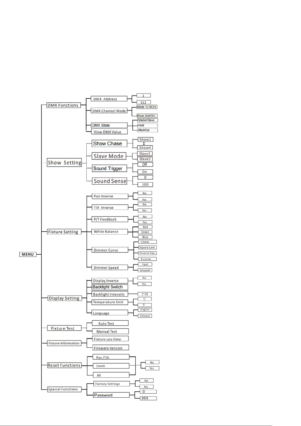
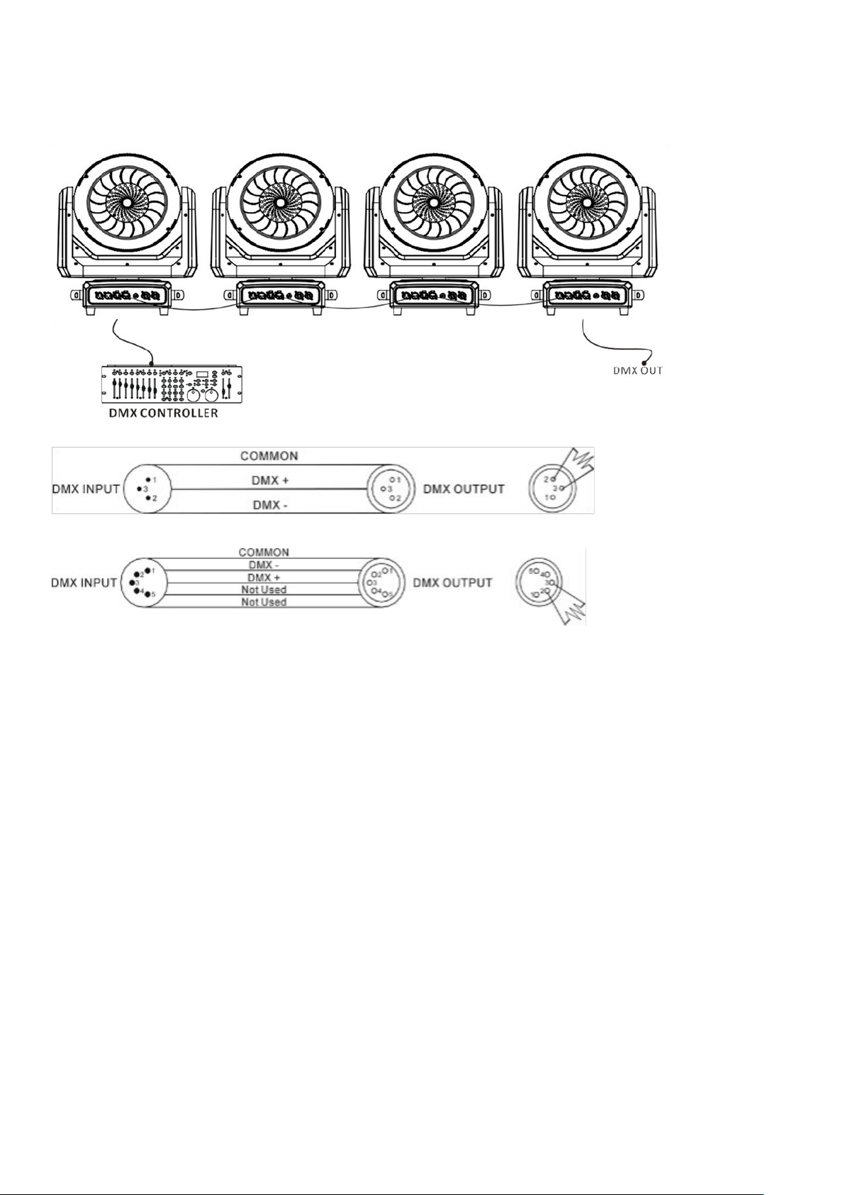
LIGHTINC MH-740 User manual

MH-740 LED WASH
MANUAL
www.light-inc.nl
INDEPENDANT
PIXEL CONTROL
BRIGHT
AND FAST
ROTATING
FRONT LENS
MOVING HEAD

THANK YOU FOR PURCHASING OUR PRODUCTS
Every unit has been thoroughly tested and has been shipped in perfect operating condition. Carefully check the
outer and inner packaging for damage that may have occurred during shipping. If the carton appears to be damaged,
carefully inspect your xture for any damage and be sure all accessories necessary to operate the unit have arrived
intact. In case damage has been found or parts are missing, please contact the distributor or your dealer for further
instructions. Do not return this unit to your dealer without rst contacting them.
1. SAFETY INFORMATION
Before operating this unit, please carefully read this manual and keep for usage in the future. It is
necessary to respect the following rules.
Disposal of the device after its life cycle can damage the environment. Take it to a recycling company or
return it to the authorized dealer.
The products referred to in this manual conform to the guidelines of the European Community and are
therefore marked with the CE logo.
Keep this device away from children and unauthorized users. The dealer is not liable for damage as a result
of ignoring the information in this manual and incorrect operation.
Before operating this unit, please make sure the housing is in good condition and ensure pan and tilt can
rotate in full range.
0.5 m
Ensure that a minimum distance of 0.5 m is maintained between the xture and any ammable material.
The device can only function with 100-240v voltage, 50 / 60Hz power. Do not connect to any other power
supply. Disconnect the device from the power supply before opening it or before maintenance.
Never look directly into the projecting lens when the xture is switched on. The light can cause epileptic
seizures in light-sensitive people or people with epilepsy. Extreme caution and compliance with these
safety instructions are required, especially with beam effects.
Do not place or install the device on a surface that is exposed to vibration or any movement.
-15°C +45°C
The device should operate in temperature range -15 °C and + 45 °C. Do not use the device if the
temperature exceeds this range.
The lens shield must be replaced if it is broken. Never use the device if the shield is not fully closed.
Safety I class device must be earthed.
When the xture is mounted overhead, the safety rope must be attached to the correct mounting location
on the bottom of the device.
Please note that damage caused by manual changes to the device is not covered by the warranty.
If possible, recycle all packaging material.

2. INSTALLATION
The xture should be mounted using its Omega Quick Release Clamp bracket. Always ensure that the unit is
securely xed to prevent vibration and slipping during operation. Make sure that the structure to which you are
attaching the unit is sturdy and capable of supporting a weight that is 10 times that of the xture. When installing,
always use a safety cable that can support a weight 12 times that of the xture.
The equipment must be installed by professionals. It should be positioned in a location that is inaccessible to
people and where no one can walk by or underneath it.
3. TECHNICAL SPECIFICATIONS
POWER VOLTAGE: AC 100~240V, 50/60HZ
POWER CONSUMPTION: 320W
LIGHT SOURCE: 7PCSX40W RGBW LED
ZOOM RANGE: 4°~55°
MOVEMENT: PAN: 540°
TILT: 270°
PAN/TILT RESOLUTION: 16BIT
DIMMING/STROBE: 0~100% SMOOTH DIMMING, VARIABLE STROBE SPEEDS
CONTROL: DMX CHANNEL: 16/44 CHANNELS
CONTROL MODE: DMX, MASTER/SLAVE
FIRMWARE UPGRADE: UPDATE VIA DMX LINK
CONSTRUCTION: DISPLAY: LCD DISPLAY
DATA IN/OUT: 3-PIN XLR
POWER IN/OUT: POWER CON IN/OUT PROTECTION RATING: IP20
FEATURES: ELECTRONIC LINEAR ZOOM SYSTEM, PIXEL CONTROL
DIMENSION: 315×235×420MM, WEIGHT:5,1KG
4. HOW TO SET THE UNIT
4.1 Control Panel
1. Display: To show the various menus and the selected functions
2. Button:
MENU Use this to move backward or exit the current menu.
DOWN ▼Use this to move forward in the selected functions.
UP ▲Use this to move backward in the selected functions.
ENTER Use this to conrm the chosen functions.
3. DMX IN: DMX512 link, use 3 XLR cable to link the unit and the DMX controller
4. DMX OUT: DMX512 link, use 3 XLR cable to link the next unit and output DMX signal
5. MAINS IN: To connect to the main supply
6. MAINS OUT: To connect to the next unit
7. Fuse(T 10A): Protects the unit from over-voltage or short circuit
12 2
3 574 6

4.2 Main function
To power on the unit, press the MENU button to enter the menu mode. Then, use the UP/DOWN buttons to
navigate until the desired function is displayed on the monitor. Conrm your selection by pressing the ENTER
button. For submenus, use the UP/DOWN button to make your choice, and press ENTER to save and
automatically return to the previous menu.
To exit the menu mode, press the MENU button or allow the unit to idle for one minute. The main functions are
listed below:

DMX Functions
To access MENU mode, select DMX Functions, then press the ENTER button to conrm. Use the UP/DOWN
button to choose between DMX Address, DMX Channel Mode, or View DMX Value.
DMX Address
For DMX Address selection, press ENTER to conrm. Use the UP/DOWN button to adjust the address from 001
to 512, then press ENTER to set up. To return to the previous menu, press the MENU button or let the unit idle
for one minute to exit menu mode.
DMX Channel Mode
For DMX Channel Mode selection, press ENTER to conrm. Use the UP/DOWN button to choose between
Mode 1 (16) or Mode 2 (44), then press ENTER to set up. To return to the previous menu, press the MENU but-
ton or let the unit idle for one minute to exit menu mode.
DMX State
To select DMX State Mode, press ENTER to conrm. Use the UP/DOWN button to select Hold or Blackout, then
press ENTER to set up. To return to the previous menu, press the MENU button or let the unit idle for one minute
to exit menu mode.
View DMX Value
To choose View DMX Value, press ENTER to conrm. Use the UP/DOWN button to view the DMX channel
values. To return to the previous menu, press the MENU button or let the unit idle for one minute to exit menu
mode.
Fixture Setting
Enter MENU mode, select Fixture Setting, press the ENTER button to conrm, use the UP/DOWN button to
select Pan Inverse, Tilt Inverse, P/T Feedback, BL.O. P/T Moving, White Balance, Cooling Mode, Dimmer Curve or
Dimmer Speed.
Pan Inverse
To select Pan Inverse, press the ENTER button to conrm. Use the UP/DOWN button to select No (normal) or
Yes (pan inverse), and press the ENTER button to set up. Press the MENU button to return to the previous menu
or let the unit idle for one minute to exit menu mode.
Tilt Inverse
To select Tilt Inverse, press the ENTER button to conrm. Use the UP/DOWN button to select No (normal) or
Yes (tilt inverse), and press the ENTER button to set up. Press the MENU button to return to the previous menu
or let the unit idle for one minute to exit menu mode.
P/T Feedback
To select P/T Feedback, press the ENTER button to conrm. Use the UP/DOWN button to select No (Pan or tilt’s
position will not feedback while out of step) or Yes (Feedback while pan/tilt out of step), and press the ENTER
button to set up. Press the MENU button to return to the previous menu or let the unit idle for one minute to exit
menu mode.
White Balance
To select White Balance, press the ENTER button to conrm. Use the UP/DOWN button to select Red, Green, or
Blue. Once selected, press the ENTER button to conrm, and use the UP/DOWN button to adjust the value from
125 to 255, and press the ENTER button to set up. Press the MENU button to return to the previous menu or let
the unit idle for one minute to exit menu mode.

Dimmer Curve
To select Dimmer Curve, press the ENTER button to conrm. Use the UP/DOWN button to select Linear, Square
Law, Inverse Squ. or S-Curve. Once selected, press the ENTER button to store. Press the MENU button to return
to the previous menu or let the unit idle for one minute to exit menu mode.
Dimmer Curve Options:
Linear: The increase in light intensity appears linear as the DMX value is increased.
Square Law: Light intensity control is ner at low levels and coarser at high levels.
Inverse Square Law: Light intensity control is coarser at low levels and ner at high levels.
S-Curve: Light intensity control is ner at both low and high levels and coarser at medium levels.
Dimmer Speed
To select Dimmer Speed, press the ENTER button to conrm. Use the UP/DOWN button to select Fast or
Smooth. Once selected, press the ENTER button to set up. Press the MENU button to return to the previous
menu or let the unit idle for one minute to exit menu mode.
Display Setting
Enter MENU mode, select Display Setting, press the ENTER button to conrm, and use the UP/DOWN button to
select Display Inverse, Backlight Auto Off, Backlight Intensity, Temperature unit, or Display Warning.
Display Inverse
To select Display Inverse, press the ENTER button to conrm. Use the UP/DOWN button to select No (normal)
or Yes (display inverse). Once selected, press the ENTER button to store. Press the MENU button to return to
the previous menu or let the unit idle for one minute to exit menu mode.
Backlight Switch
To select Backlight Switch, press the ENTER button to conrm. Use the UP/DOWN button to select No (display
always on) or Yes (display goes off one minute after exiting menu mode). Once selected, press the ENTER button
to conrm and store. Press the MENU button to return to the previous menu or let the unit idle for one minute to
exit menu mode.
Backlight Intensity
To select Backlight Intensity, press the ENTER button to conrm. Use the UP/DOWN button to adjust the inten-
sity from 1 (dark) to 10 (bright). Once selected, press the ENTER button to set up and store. Press the MENU
button to return to the previous menu or let the unit idle for one minute to exit menu mode.
Temperature Unit
To Select Temperature Unit, press the ENTER button to conrm. Use the UP/DOWN button to select ºC or ºF,
and press the ENTER button to store. Press the MENU button to return to the previous menu or let the unit idle
for one minute to exit menu mode.
Language
To select Language, press the ENTER button to conrm. Use the UP/DOWN button to select
English or Chinese will show the error warning when the unit goes wrong), press the
ENTER button to store. Press the MENU button to return to the previous menu or let the unit idle for one minute
to exit menu mode.

Fixture Test
Enter MENU mode, select Fixture Test, press the ENTER button to conrm, use the UP/DOWN
button to select Auto Test or Manual Test
Auto Test
To select Auto Test, press the ENTER button to conrm, the unit will run built-in programs to automatically test
pan, tilt, dimmer, shutter, spe.fun and etc. Press the MENU button to return to the previous menu or exit menu
mode after the auto-test.
Manual Test
To select Manual Test, press the ENTER button to conrm. Use the UP/DOWN button to select a channel, and
adjust the channel value. Once selected, press the ENTER button to set up, the xture will run as the channel
value indicates. Press the MENU button to return to the previous menu or let the unit idle for one minute to exit
menu mode. (All channels’ values will become 0 after exiting the Manual Test menu)
Fixture Information
Enter MENU mode, select Fixture Information, press the ENTER button to conrm, and use the UP/DOWN but-
ton to select Fixture use time, LED On time, or Firmware Version.
Fixture use time
To select Fixture use time, press the ENTER button to conrm, the xture working hours will show on the display.
Press the MENU button to exit.
Firmware Version
To select Firmware Version, press the ENTER button to conrm, the xture software version will show on the
display. Press the MENU button to exit.
Reset Functions
Enter MENU mode, select Reset Functions, press the ENTER button to conrm, use the UP/DOWN
button to select Pan/Tilt, Zoom, or All.
Pan/Tilt
To Select Pan/Tilt, press the ENTER button to conrm. Use the UP/DOWN button to select No or Yes (the unit
will run a built-in program to reset the pan and tilt to their home positions), and press the ENTER button to store.
Press the MENU button to exit menu mode.
Zoom
To select Zoom, press the ENTER button to conrm. Use the UP/DOWN button to select No or Yes (the unit
will run a built-in program to reset zoom to its home positions), and press the ENTER button to store. Press the
MENU button to exit menu mode.
All
To select All, press the ENTER button to conrm. Use the UP/DOWN button to select No or Yes (the unit will run
a built-in program to reset all motors to their home positions), and press the ENTER button to store. Press the
MENU button to exit menu mode.
Special Functions
Enter MENU mode, select Special Functions, press the ENTER button to conrm, use the
UP/DOWN button to select Fixture Maintenance or Factory Setting.

Fixture Maintenance
To select Fixture Maintenance, press the ENTER button to conrm. Use the UP/DOWN button to choose
between Interval or Remain Time. For Interval, press the ENTER button to conrm; the interval time will be
displayed. Press the MENU button to exit. For Remain Time, press the ENTER button to conrm; the remaining
time will be displayed. Press ENTER again to conrm, then press the MENU button to exit.
Factory Setting
For selecting Factory Setting, press the ENTER button to conrm. Use the UP/DOWN button to choose between
No or Yes (the xture will reset to factory settings and exit menu mode).
4.3 Home Position Adjustment
Press the MENU button to enter menu mode, then press the ENTER button for about 3 seconds to enter offset
mode for adjusting the home position. Select the function with the ENTER button. Use the UP/DOWN button
to choose the submenu, press the ENTER button to save and automatically return to the last menu. Press the
MENU button to exit.
In the main functions, hold the ENTER button for at least 3 seconds to enter offset mode. Use the DOWN/UP
button to select Pan, Tilt, or Zoom, and press the ENTER button to conrm. Adjust the home position of Pan, Tilt,
or Zoom using the DOWN/UP buttons. Once the position is selected, press the ENTER button to set up.
To return to the functions without changes, press the MENU button. Press and hold the MENU button for about
one second or wait for about one minute to exit the menu mode.

5. CONTROL BY UNIVERSAL DMX CONTROLLER
5.1 DMX512 Connection
1. DMX Cable Termination: At the last unit, the DMX cable must be terminated with a terminator. Solder a 120-
ohm 1/4W resistor between pin 2 (DMX-) and pin 3 (DMX+) into a 3-pin XLR plug. Then, plug it into the DMX
output of the last unit.
2. Connection Method: Connect the units together in a “daisy chain” using XLR plug cables. Connect the output
of one unit to the input of the next unit. Do not branch or split the cable to create a “Y” cable. DMX 512 is a
high-speed signal, and using inadequate, damaged cables, soldered joints, or corroded connectors can distort
the signal and cause system shutdown.
3. Pass-Through Connectors: The DMX output and input connectors act as pass-through to maintain the DMX
circuit even when the power of one of the units is disconnected.
4. DMX Addressing: Each lighting unit requires a unique DMX address to receive data from the controller. The
address number typically ranges between 0 and 511 (commonly, 0 and 1 are equivalent to 1).
5. Termination for Signal Quality: Terminate the end of the DMX 512 system to reduce signal errors and ensure
proper signal quality.
6. XLR Connector Types: 3-pin XLR connectors are more widely used than 5-pin XLR connectors.
• 3-pin XLR: Pin 1: GND, Pin 2: Negative signal (-), Pin 3: Positive signal (+)
• 5-pin XLR: Pin 1: GND, Pin 2: Negative signal (-), Pin 3: Positive signal (+), Pin 4 and Pin 5 are not used.

5.2 Address Setting
If you use a universal DMX controller to control the units, you have to set the DMX address from 1 to 512 so that
the units can receive the DMX signal.
Press the MENU button to enter menu mode, select DMX Functions, press the ENTER button to conrm, use
the UP/DOWN button to select DMX Address, and press the ENTER button to conrm, the present address will
blink the display, use the UP/DOWN button to adjust the address from 001 to 512, press the ENTER button to
store.
To return to the previous menu, press the MENU button, or let the unit idle for one minute to exit menu mode.
Please refer to the following diagram to address your DMX512 channel for the rst 4 units.
Channel Mode Unit 1
Address
Unit 2
Address
Unit 3
Address
Unit 4
Address
16 channels 1 17 33 49
44 channels 1 45 89 133
5.3 DMX512 Conguration
Please refer to below congurations to control the xtures
Attention:
1. The unit will retain its last state until reset, even if the DMX signal is disconnected.
2. To activate a specic function for a channel, maintain the value for about 5 seconds, and the corresponding
function will then come into effect.
16 Ch. Channel Value Function
1Pan
000-255 0°-540°
2Tilt
000-255 0°-220°
3Pan/Tilt speed
000-255 Fast -> Slow
4Zoom
0-255 Wide (55°) -> Small (4°)
5
Lens rotation
000-127 Index
128-191 Clockwise rotation Fast -> Slow
192-255 Counter clockwise rotation Slow -> Fast
6
Shutter
000-019 Off
020-024 Open
025-064 Strobe Fast -> Slow
065-069 Open
070-084 Pulse, fast close slow open Fast -> Slow
085-089 Open
090-104 Pulse fast open slow close Fast -> Slow

Channel Value Function
6
105-109 Open
110-124 Strobe
Fast -> Slow
125-129 Open
130-144 Pulse, fast close slow open
Fast -> slow
145-149 Open
150-164 Pulse fast open slow close
Fast -> Slow
165-169 Open
170-184 Dimmer macro burst pulse
Fast -> Slow
185-189 Open
190-204 Dimmer macro burst pulse
Fast -> Slow
205-209 Open
210-224 Dimmer macro slow open slow close
Fast -> Slow
225-229 Open
230-244 Dimmer macro burst little
Fast -> Slow
245-255 Open
7Dimmer
000-255 0% -> 100%
8Red
000-255 0% -> 100%
9Green
000-255 0% -> 100%
10 Blue
000-255 0% -> 100%
11 White
000-255 0% -> 100%
12
Colour macro
000-009 No macro colour
010-014 White 1
015-019 Light pink
020-024 Deep pink
025-029 Pink
030-034 Lavender
035-039 Light cyan 1
040-044 Light sky blue
045-049 Deep sky blue
050-054 Cyan 1
055-059 Light blue

Channel Value Function
12
060-064 Powder blue
065-074 Light cyan 2
075-079 Light cyan 3
080-084 White 2
085-089 White 3
090-094 Light cyan 4
095-099 Cyan 2
100-104 Soft aquamarine
105-109 Green 1
110-114 Green 2
115-119 Green 3
120-124 Green 4
125-129 Green 5
130-134 Yellow 1
135-139 Yellow 2
140-144 Yellow 3
145-149 Green 6
150-154 Yellow 4
155-159 Dark yellow 1
160-164 Dark yellow 2
165-169 Yellow 5
170-174 Orange
175-179 No macro colour
180-204 Forward macro fade
Fast -> Slow
205-229 Backward macro fade
Slow -> fast
230-234 No macro colour
235-249 Colour jump
Fast -> Slow
250-255 No macro colour
13
Macro program
individually controlled LEDs
000-007 Off
008-023 Program 1
024-039 Program 2
040-055 Program 3
056-071 Program 4
072-087 Program 5
088-103 Program 6
104-119 Program 7
120-135 Program 8
136-151 Program 9

Channel Value Function
13
152-167 Program 10
168-183 Program 11
184-199 Program 12
200-215 Program 13
216-231 Program 14
232-247 Program 15
248-255 Program 16
14
Colour of macro program individually
controlled LEDs
000-017 White 1
018-024 Light pink
025-032 Deep pink
033-039 Pink
040-047 Lavender
048-054 Light cyan 1
055-061 Light sky blue
062-069 Deep sky blue
070-076 Cyan 1
077-084 Light blue
085-091 Powder blue
092-106 Light cyan 2
107-113 Light cyan 3
114-121 White 2
122-128 White 3
129-136 Light cyan 4
137-143 Cyan 2
144-151 Soft aquamarine
152-158 Green 1
159-165 Green 2
166-173 Green 3
174-180 Green 4
181-188 Green 5
189-195 Yellow 1
196-203 Yellow 2
204-210 Yellow 3
211-217 Green 6
218-225 Yellow 4
226-232 Dark yellow 1
233-240 Dark yellow 2
241-247 Yellow 5
248-255 Orange
15 Macro program speed
000-255 Slow -> Fast

Channel Value Function
16
Reset
000-009 Nothing
010-019 Reset all
020-029 Zoom / lens rotation reset
030-039 Pan / tilt reset
040-255 Nothing
44 Ch. Channel Value Function
1Pan
000-255 0°-540°
2000-255 Pan ne
3Tilt
000-255 0°-220°
4000-255 Tilt ne
5Pan/Tilt speed
000-255 Fast -> Slow
6Zoom
0-255 Wide (55°) -> Small (4°)
7000-255 Zoom ne
8
Lens rotation
000-127 Index
128-191 Clockwise rotation
Fast -> Slow
192-255 Counter clockwise rotation
Slow -> Fast
9
Shutter
000-019 Off
020-024 Open
025-064 Strobe
Fast -> Slow
065-069 Open
070-084 Pulse, fast close slow open
Fast -> Slow
085-089 Open
090-104 Pulse fast open slow close
Fast -> Slow
105-109 Open
110-124 Strobe
Fast -> slow
125-129 Open
130-144 Pulse, fast close slow open
Fast -> Slow
145-149 Open
150-164 Pulse fast open slow close
Fast -> Slow

Channel Value Function
9
165-169 Open
170-184 Dimmer macro burst pulse
Fast -> Slow
185-189 Open
190-204 Dimmer macro burst pulse
Fast -> Slow
205-209 Open
210-224 Dimmer macro slow open slow close
Fast -> Slow
225-229 Open
230-244 Dimmer macro burst little
Fast -> Slow
245-255 Open
10 Dimmer
000-255 0% -> 100%
11 000-255 Dimmer ne
12 Red 1
000-255 0% -> 100%
13 Green 1
000-255 0% -> 100%
14 Blue 1
000-255 0% -> 100%
15 White 1
000-255 0% -> 100%
16 Red 2
000-255 0% -> 100%
17 Green 2
000-255 0% -> 100%
18 Blue 2
000-255 0% -> 100%
19 White 2
000-255 0% -> 100%
20 Red 3
000-255 0% -> 100%
21 Green 3
000-255 0% -> 100%
22 Blue 3
000-255 0% -> 100%
23 White 3
000-255 0% -> 100%
24 Red 4
000-255 0% -> 100%
25 Green 4
000-255 0% -> 100%

Channel Value Function
26 Blue 4
000-255 0% -> 100%
27 White 4
000-255 0% -> 100%
28 Red 5
000-255 0% -> 100%
29 Green 5
000-255 0% -> 100%
30 Blue 5
000-255 0% -> 100%
31 White 5
000-255 0% -> 100%
32 Red 6
000-255 0% -> 100%
33 Green 6
000-255 0% -> 100%
34 Blue 6
000-255 0% -> 100%
35 White 6
000-255 0% -> 100%
36 Red 7
000-255 0% -> 100%
37 Green 7
000-255 0% -> 100%
38 Blue 7
000-255 0% -> 100%
39 White 7
000-255 0% -> 100%
40
Colour macro
000-009 No macro colour
010-014 White 1
015-019 Light pink
020-024 Deep pink
025-029 Pink
030-034 Lavender
035-039 Light cyan 1
040-044 Light sky blue
045-049 Deep sky blue
050-054 Cyan 1
055-059 Light blue
060-064 Powder blue
065-074 Light cyan 2
075-079 Light cyan 3

Channel Value Function
40
080-084 White 2
085-089 White 3
090-094 Light cyan 4
095-099 Cyan 2
100-104 Soft aquamarine
105-109 Green 1
110-114 Green 2
115-119 Green 3
120-124 Green 4
125-129 Green 5
130-134 Yellow 1
135-139 Yellow 2
140-144 Yellow 3
145-149 Green 6
150-154 Yellow 4
155-159 Dark yellow 1
160-164 Dark yellow 2
165-169 Yellow 5
170-174 Orange
175-179 No macro colour
180-204 Forward macro fade
Fast -> slow
205-229 Backward macro fade
Slow -> Fast
230-234 No macro colour
235-249 Colour jump
Fast -> Slow
250-255 No macro colour
41
Macro program
individually controlled LEDs
000-007 Off
008-023 Program 1
024-039 Program 2
040-055 Program 3
056-071 Program 4
072-087 Program 5
088-103 Program 6
104-119 Program 7
120-135 Program 8
136-151 Program 9
152-167 Program 10
168-183 Program 11
184-199 Program 12
200-215 Program 13

Channel Value Function
41
216-231 Program 14
232-247 Program 15
248-255 Program 16
42
Colour of macro program
individually controlled LEDs
000-017 White 1
018-024 Light pink
025-032 Deep pink
033-039 Pink
040-047 Lavender
048-054 Light cyan 1
055-061 Light sky blue
062-069 Deep sky blue
070-076 Cyan 1
077-084 Light blue
085-091 Powder blue
092-106 Light cyan 2
107-113 Light cyan 3
114-121 White 2
122-128 White 3
129-136 Light cyan 4
137-143 Cyan 2
144-151 Soft aquamarine
152-158 Green 1
159-165 Green 2
166-173 Green 3
174-180 Green 4
181-188 Green 5
189-195 Yellow 1
196-203 Yellow 2
204-210 Yellow 3
211-217 Green 6
218-225 Yellow 4
226-232 Dark yellow 1
233-240 Dark yellow 2
241-247 Yellow 5
248-255 Orange
43 Macro program speed
000-255 Slow -> Fast
44
Reset
000-009 Nothing
010-019 Reset all
020-029 Zoom / lens rotation reset
030-039 Pan / tilt reset
040-255 Nothing

6. TROUBLESHOOTING
During operation, you might encounter some common problems. Here are suggestions for easy troubleshooting:
A. The unit does not work, no light, and the fan does not operate:
1. Check the power connection and the main fuse.
2. Measure the mains voltage on the main connector.
B. Not responding to DMX controller:
1. Ensure the DMX LED is active. If not, verify the DMX connectors and cables for proper connection.
2. If the DMX LED is active but there’s no response to channels, check the address settings and DMX polarity.
3. For intermittent DMX signal issues, examine the pins on connectors or the unit’s PCB, or the previous unit’s
PCB.
4. Try using a different DMX controller.
5. Inspect if DMX cables are positioned near high-voltage cables, which could lead to damage or interference to
the DMX interface circuit.
C. One channel not functioning properly:
1. The stepper motor might be damaged, or the cable connected to the PCB may be broken.
2. The motor’s drive IC on the PCB might be compromised.
7. FIXTURE CLEANING
To optimize light output, periodically clean internal and external optical lenses and/or mirrors.
The cleaning frequency depends on the xture’s operating environment; environments with dampness,
smoke, or excessive dirt can lead to greater accumulation of dirt on the unit’s optics.
Cleaning Procedure:
• Use a soft cloth and normal glass cleaning liquid.
• Ensure the components are thoroughly dried.
• Clean external optics at least every 20 days. Clean internal optics at least every 30/60 days
8. NOTES

Table of contents
Other LIGHTINC Dj Equipment manuals